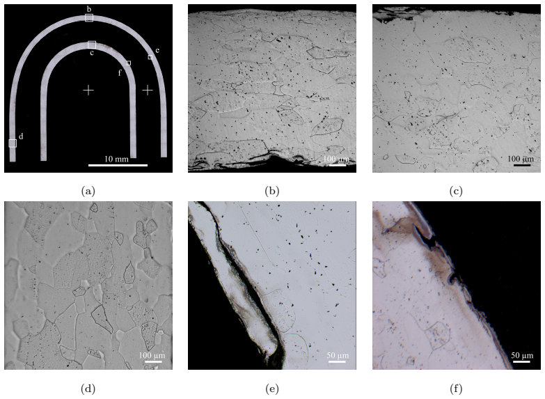
Manufacturability studies for the FCC-ee positron source target: determination of the minimum bending radius and ovalization in tantalum cooling tube elbows
Pith reviewed 2026-06-27 22:20 UTC · model grok-4.3
The pith
A minimum bending radius of 10 mm works for manufacturing tantalum cooling tube elbows with ovalization limited to 0.5 mm.
A machine-rendered reading of the paper's core claim, the machinery that carries it, and where it could break.
Core claim
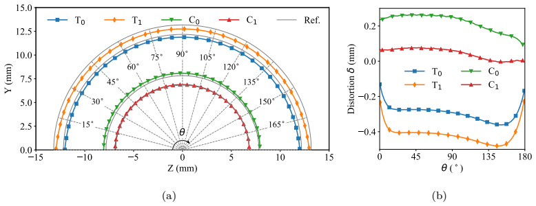
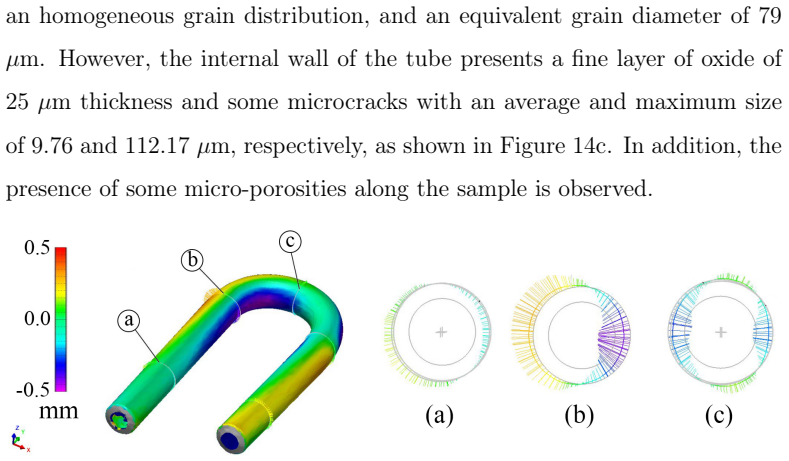
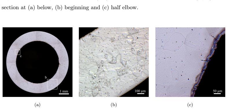
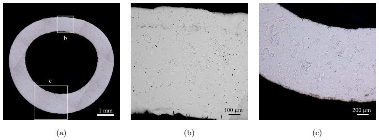
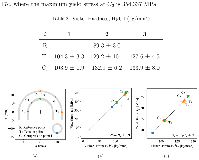
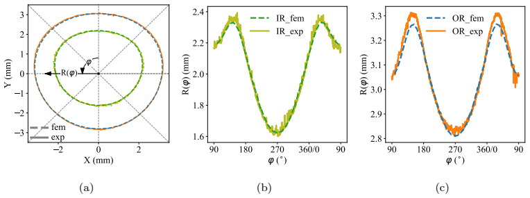
The central discovery is that the minimum bending radius for the tantalum cooling tubes is 10 mm, as determined by the numerical model. This radius produces ovalization distortion within ±0.5 mm, which constitutes an important deviation from the nominal geometry. The model was validated through experimental tests using both non-destructive and destructive methods, and micrographs of the tube cross-sections before and after bending confirm that the elbow maintains its integrity. An empirical expression is also proposed to estimate the yield stress of pure tantalum from Vickers hardness measurements. The numerical model predicts ovalization along the elbow and offers a practical method to spec
What carries the argument
Four-step numerical methodology for determining minimum bending radius in thick-walled tubes via compression bending: allowable radius calculation, constitutive law validation, ovalization prediction, and experimental confirmation.
If this is right
- The 10 mm radius elbow can be produced without loss of tube integrity.
- Ovalization must be incorporated into the final cooling channel layout.
- The validated model serves as an alternative for specifying tube geometries in other beam devices.
- Hardness measurements can substitute for direct yield stress tests in tantalum.
Where Pith is reading between the lines
- This bending approach may apply to cooling designs in other compact high-energy physics apparatus.
- Early inclusion of ovalization effects in simulations could minimize redesign cycles for accelerator components.
- Generalizing the model to varying tube thicknesses or materials would broaden its utility for custom cooling systems.
Load-bearing premise
The material model for tantalum correctly describes its behavior under the large strains and contact forces present in compression bending.
What would settle it
If bending a tube to 10 mm radius produces ovalization greater than 0.5 mm or visible damage in cross-section micrographs, the claimed minimum radius would be invalidated.
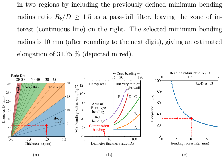
Figures
read the original abstract
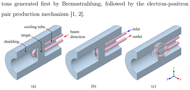
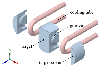
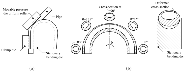
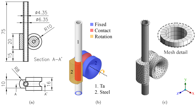
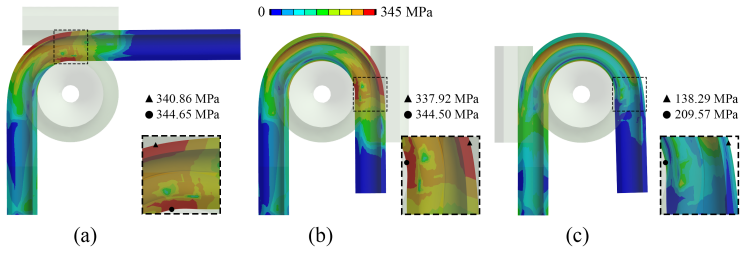
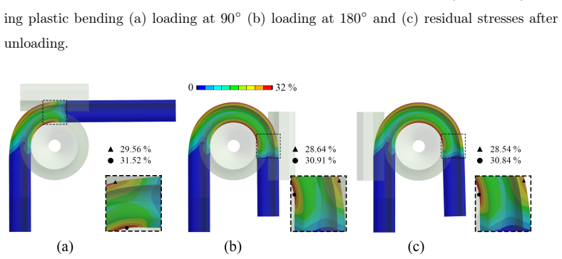
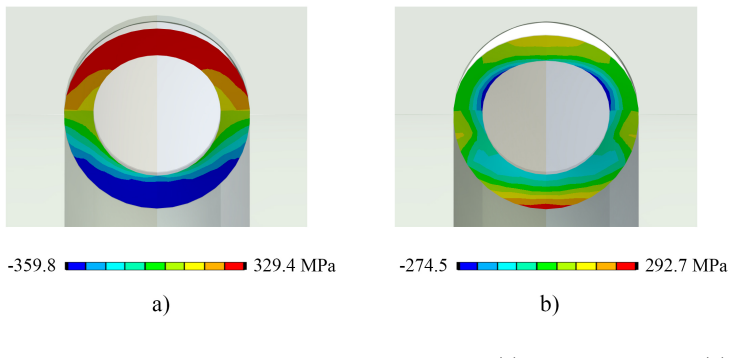
Beam intercepting devices rely on cooling systems to effectively dissipate the thermal energy generated during the impact of a high-energy beam. Regardless of the device's size, integrating the cooling system is a complex task, particularly when the resulting device is only a few centimetres in size, as is the case with the positron source target for the Future Circular Collider at CERN, where the current design consists of a tungsten core with two embedded tantalum cooling tubes. Due to the reduced dimensions of the chosen tantalum tubes (OD6.35xID4.35 mm), the selected manufacturing method is compression bending. The present study develops and evaluates a numerical model to manufacture the required elbow. The methodology is divided in four steps: i) minium allowable bending radius calculation, ii) material constitutive law validation, iii) prediction of the resulting distortion due to ovalization and iv) experimental validation via (non) destructive methods. The results indicate that a minimum bending radius of 10 mm is suitable for manufacturing the elbow. The distortion caused by ovalization is within +-0.5 mm, resulting in an important deviation respect to the nominal geometry. The numerical model was successfully validated experimentally. The micrographies performed in the cross-section of the tantalum tube before and after plastic bending confirm the integrity of the elbow. Additionally, an empirical expression is proposed to estimate the yield stress of pure tantalum based on Vickers hardness measurements. The proposed numerical model is capable to predict the ovalization along the resulting elbow, offering a viable alternative to define the cooling tube geometry. This study provides a methodology to determine the minimum bending radius for thick walled tubes to be used with compression bending and can be applied for the cooling system design of other high-performance devices
Editorial analysis
A structured set of objections, weighed in public.
Referee Report
Summary. The paper develops a four-step numerical-experimental methodology for compression bending of small-diameter thick-walled tantalum tubes (OD 6.35 mm) intended for the FCC-ee positron source target cooling system. Step (i) determines a minimum allowable bending radius; step (ii) validates an elastoplastic constitutive law; step (iii) predicts ovalization-induced distortion; and step (iv) performs experimental validation via micrographs and non-destructive checks. The central claims are that a 10 mm minimum radius is suitable, ovalization remains within ±0.5 mm (an important deviation from nominal geometry), the numerical model is validated, no cracking occurs, and an empirical yield-stress expression from Vickers hardness is provided. The work supplies a general methodology for determining minimum bending radii of thick-walled tubes.
Significance. If the constitutive-law validation and ovalization predictions hold under the reported contact and strain conditions, the study supplies a practical, transferable workflow for manufacturability assessment of compact cooling channels in beam-intercepting devices. The combination of forward numerical prediction with independent physical bending trials and hardness measurements is a strength; the proposed empirical hardness-to-yield relation could also be useful for tantalum component qualification.
major comments (2)
- [Methodology step (ii)] Methodology step (ii): the claim that the elastoplastic law is validated for the compression-bending process is load-bearing for the ovalization prediction in step (iii) and the final suitability verdict, yet the abstract (and available description) provides no information on the hardening-law functional form, whether anisotropy or rate dependence is included, the maximum equivalent strain reached in the validation data, or how friction coefficients were measured or bounded in the contact model. Without these details it is impossible to assess whether the computed ±0.5 mm ovalization remains reliable when tooling contact and large plastic strains are present.
- [Methodology step (iv)] Step (iv) experimental validation: the micrographies are stated to confirm integrity (no cracking), but the text does not report quantitative comparison metrics (e.g., measured vs. predicted ovalization at specific angular positions along the elbow) that would close the loop on the numerical model. This weakens the assertion that the model “was successfully validated experimentally.”
minor comments (2)
- [Abstract] Abstract: “minium” should read “minimum”; “respect to the nominal geometry” should read “with respect to the nominal geometry.”
- [Abstract] The phrase “an important deviation” is ambiguous; clarify whether the ±0.5 mm ovalization is judged acceptable or problematic for the downstream cooling performance.
Simulated Author's Rebuttal
We thank the referee for the constructive comments, which help clarify the presentation of our methodology. We address each major comment below and will revise the manuscript to incorporate the requested details and metrics.
read point-by-point responses
-
Referee: [Methodology step (ii)] Methodology step (ii): the claim that the elastoplastic law is validated for the compression-bending process is load-bearing for the ovalization prediction in step (iii) and the final suitability verdict, yet the abstract (and available description) provides no information on the hardening-law functional form, whether anisotropy or rate dependence is included, the maximum equivalent strain reached in the validation data, or how friction coefficients were measured or bounded in the contact model. Without these details it is impossible to assess whether the computed ±0.5 mm ovalization remains reliable when tooling contact and large plastic strains are present.
Authors: We agree that these specifics are needed to fully evaluate the constitutive model under the reported contact and strain conditions. In the revised manuscript we will expand the description in the methods section and abstract to state the hardening-law functional form, confirm that anisotropy and rate dependence were not included, report the maximum equivalent strain from the validation data, and explain the selection and bounding of the friction coefficient (including any sensitivity checks performed). revision: yes
-
Referee: [Methodology step (iv)] Step (iv) experimental validation: the micrographies are stated to confirm integrity (no cracking), but the text does not report quantitative comparison metrics (e.g., measured vs. predicted ovalization at specific angular positions along the elbow) that would close the loop on the numerical model. This weakens the assertion that the model “was successfully validated experimentally.”
Authors: We acknowledge that the current validation description relies primarily on qualitative confirmation of no cracking and overall geometric compliance. We will revise the manuscript to add quantitative comparison metrics, including measured versus predicted ovalization values at specific angular positions along the elbow, drawn from the available micrograph and non-destructive test data. revision: yes
Circularity Check
No significant circularity; forward simulation validated by independent experiments
full rationale
The derivation proceeds from a four-step methodology: (i) analytic minimum-radius calculation, (ii) separate calibration/validation of the tantalum elastoplastic law against hardness and tensile data, (iii) forward finite-element prediction of ovalization under that law, and (iv) experimental bending trials plus micrography that close the loop on the predictions. None of the load-bearing outputs (R_min = 10 mm, ovalization ±0.5 mm) are defined in terms of themselves or obtained by renaming fitted quantities; the empirical yield-stress expression is an auxiliary fit, not the central claim. No self-citation load-bearing steps, uniqueness theorems, or ansatz smuggling appear. The chain is therefore self-contained against external benchmarks.
Axiom & Free-Parameter Ledger
free parameters (2)
- minimum bending radius =
10 mm
- ovalization tolerance =
±0.5 mm
axioms (2)
- domain assumption Tantalum obeys an elastoplastic constitutive law that can be calibrated and validated for the strain rates and temperatures of compression bending.
- domain assumption Finite-element simulation of the bending process captures the dominant deformation modes without requiring additional correction terms for contact or friction.
Reference graph
Works this paper leans on
-
[1]
M. Benedikt, F. Zimmermann, B. Auchmann, et al., Future Circular Collider Feasibility Study Report. Volume 2: Accelerators, Technical Infrastructure and Safety, The European Physical Journal Special Top- ics 234 (19) (2025) 5713–6197. doi:10.1140/epjs/s11734-025-01967-4
-
[2]
J. H. Hubbell, Electron–positron pair production by photons: A his- torical overview, Radiation Physics and Chemistry 75 (2006) 614–623. doi:10.1016/j.radphyschem.2005.10.008
-
[3]
E. Lassner, W.-D. Schubert, Tungsten: properties, chemistry, technol- ogy of the element, alloys, and chemical compounds, Kluwer Academic / Plenum Publishers, New York, 1999. doi:10.1007/978-1-4615-4907-9
-
[4]
M. J. Cardillo, Y. Look, The reaction of tungsten with CO2 and D2O 33 at high temperatures and low pressures, Surface Science 66 (1) (1977) 272–298. doi:10.1016/0039-6028(77)90412-5
-
[5]
G. A. Greene, C. C. Finfrock, Vaporization of tungsten in flowing steam at high temperatures, Experimental Thermal and Fluid Sciences 25 (2001) 87–99. doi:10.1016/S0894-1777(01)00063-2
-
[6]
S. M. Cardonne, P. Kumar, C. A. Michaluk, H. D. Schwartz, Tantalum and its Alloys, Int. J. of Refractory Metals & Hard Materials 13 (1995) 187–194. doi:10.1016/0263-4368(95)94023-R
-
[7]
M. Kawai, K. Kikuchi, H. Kurishita, J.-F. Li, M. Furusaka, Fabrica- tion of a tantalum-clad tungsten target for KENS, Journal of Nuclear Materials 296 (1) (2001) 312–320. doi:10.1016/S0022-3115(01)00533-5
-
[8]
D. Wilcox, P. Loveridge, T. Davenne, L. Jones, D. Jenkins, Stress levels and failure modes of tantalum-clad tungsten targets at ISIS, Journal of Nuclear Materials 506 (2018) 76–82. doi:10.1016/j.jnucmat.2017.10.075
-
[9]
J. Busom Descarrega, M. Calviani, T. Hutsch, E. López Sola, A. T. Pérez Fontenla, A. Perillo Marcone, S. Sgobba, T. Weißgärber, Ap- plication of Hot Isostatic Pressing (HIP) technology to diffusion bond refractory metals for proton beam targets and absorbers at CERN, Material Design & Processing Communications 2 (1) (2020) e101. doi:10.1002/mdp2.101
-
[10]
A. Romero-Francia, A. Perillo-Marcone, S. Pianese, K. Andersen, et al., Design and early operation of a new-generation internal beam dump for 34 CERN’s Super Proton Synchrotron, Phys. Rev. Accel. Beams 27 (2024) 043001. doi:10.1103/PhysRevAccelBeams.27.043001
-
[11]
Bertarelli, O
A. Bertarelli, O. Aberle, R. Assmann, E. Chiaveri, T. Kurtyka, M. Mayer, R. Perret, P. Sievers, The Mechanical Design for the LHC Collimators, Tech. rep., CERN-LHC Project Report 786 (2004). URLhttps://cds.cern.ch/record/794628
2004
-
[12]
C. T. Olofson, A review of Bending Methods for Stainless Steeel Tubing, Tech. rep., DMIC Report 150 (1961)
1961
-
[13]
K. Pan, K. A. Stelson, On the Plastic Deformation of a Tube Dur- ing Bending, Jorunal of Engineering for Industry 117 (1995) 494–500. doi:10.1115/1.2803526
-
[14]
N. Tang, Plastic-deformation analysis in tube bending, Interna- tional Journal of Pressure Vessels and Piping 77 (2000) 751–759. doi:10.1016/S0308-0161(00)00061-2
-
[15]
H. A. Al-Qureshi, Elastic-plastic analysis of tube bending, Interna- tional Journal of Machine Tools & Manufacture 39 (1999) 87–104. doi:10.1016/S0890-6955(98)00012-1
-
[16]
A. El-Megharbel, G. A. El-Nasser, A. El-Domiaty, Bending of tube and section made of strain-hardening materials, Jour- nal of Materials Processing Technology 203 (2008) 372–380. doi:10.1016/j.jmatprotec.2007.10.078
-
[17]
M. Murata, T. Kuboki, K. Takahashi, M. Goodarzi, Y. Jin, Effect of hardening exponent on tube bending, Journal of 35 Materials Processing Technology 201 (1) (2008) 189–192. doi:10.1016/j.jmatprotec.2007.11.286
-
[18]
Paulsen, T
F. Paulsen, T. Welo, An Analytical Model for Prediction of Tube Oval- ization in Bending, in: ESAFORM 2003: Proceedings of the Sixth ESAFORM Conference on Material Forming, 2003, pp. 775–778
2003
-
[19]
S. A. Tronvoll, J. Ma, T. Welo, Deformation behavior in tube bending: a comparative study of compression bending and rotary draw bending, Int J Adv Manuf Technol 124 (2023) 801–8016. doi:10.1007/s00170-022- 10433-7
-
[20]
D. Munz, C. Mattheck, Cross-sectional flattening of pipes subjected to bending, International Journal of Pressure Vessels and Piping 10 (1982) 421–429. doi:10.1016/0308-0161(82)90003-5
-
[21]
Miller, Tube Forming Processes: A Comprehensive Guide, Society of Manufacturing Engineers, Dearborn - Michigan, 2003
G. Miller, Tube Forming Processes: A Comprehensive Guide, Society of Manufacturing Engineers, Dearborn - Michigan, 2003
2003
-
[22]
Springborn, Cold Bending and Forming Tube and other sections, America Society of Tool and Manufacturing Engineers, Dearborn - Michigan, 1966
R. Springborn, Cold Bending and Forming Tube and other sections, America Society of Tool and Manufacturing Engineers, Dearborn - Michigan, 1966
1966
-
[23]
Jehring, T
U. Jehring, T. Flutsch, M. Farajian, C. Schweizer, Final Report - Ma- terial Characterization, Project: Supply and characterization of HIPed blocks with refractory metals for beam intercepting devices application, Tech. rep., Fraunhofer Institute for Manufacturing Technology and Ad- vanced Materials IFAM (2020). 36
2020
-
[24]
E. Lopez Sola, M. Calviani, P. Avigni, M. Battistin, et al., De- sign of a high power production target for the beam dump fa- cility at CERN, Phys. Rev. Accel. Beams 22 (2019) 113001. doi:10.1103/PhysRevAccelBeams.22.113001
-
[25]
Ansys Inc., Ansys Academic Research Mechanical, 2022 R2 (2022)
2022
-
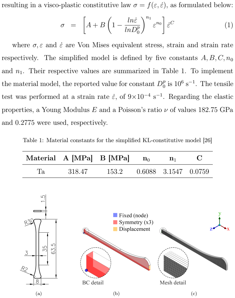
[26]
A. S. Khan, R. Liang, Behaviors of three BCC metal over a wide range of strain rates and temperatures: experiments and modeling, International Journal of Plasticity 15 (10) (1999) 1089–1109. doi:10.1016/S0749- 6419(99)00030-3
-
[27]
M. B. Prime, A. Arsenlis, R. A. Austin, N. R. Barton, et al., A broad study of tantalum strength from ambient to extreme conditions, Acta Materialia 231 (2022) 117875. doi:10.1016/j.actamat.2022.117875
-
[28]
D. Colas, E. Finot, S. Flouriot, S. Forest, M. Mazière, T. Paris, In- vestigation and modeling of the anomalous yield point phenomenon in pure tantalum, Materials Science & Engineering A 615 (2014) 283–295. doi:10.1016/j.msea.2014.07.028
-
[29]
ASTM-B521-12, Standard Specification for Tantalum and Tantalum Al- loy Seamless and Welded Tubes, Standard, American Society for Testing and Materials (ASTM), Philadelphia, USA (2012). doi:10.1520/B0521- 12
-
[30]
M. Tiryakioˇ glu, J. S. Robinson, M. A. Salazar-Guapuriche, Y. Y. Zhao, P. D. Eason, Hardness–strength relationships in the aluminum 37 alloy 7010, Materials Science & Engineering A 631 (2015) 196–200. doi:10.1016/j.msea.2015.02.049
-
[31]
M. Tiryakioˇ glu, On the relationship between Vickers hardness and yield stress in Al–Zn–Mg–Cu alloys, Materials Science & Engineering A 633 (2015) 17–19. doi:10.1016/j.msea.2015.02.073. 38
discussion (0)
Sign in with ORCID, Apple, or X to comment. Anyone can read and Pith papers without signing in.