REVIEW 4 major objections 6 minor 54 references
Variable zoom digital in-line holographic microscopy
T0 review · 4 major / 6 minor · reviewed 2026-08-10 · deepseek-v4-flash
Pith's one-line read One tunable lens zooms a lensless microscope from 15X to 35X by shifting the illumination point electrically.
desk verdict A solid incremental result: an ETL-based variable zoom in DIHM, directly measured and honestly framed, with fixable presentation gaps in Eq. (2) and the phase cross-check. read the letter →
The pith
A machine-rendered reading of the paper's core claim, the machinery that carries it, and where it could break.
The reading
What carries the argument
ETL-induced axial source shift. An electrically tunable lens, whose optical power changes with applied voltage, is placed in the collimated illumination beam just before the focusing lens. Changing its power moves the effective point source by $\Delta z \approx f_{FL}'^2/(f_{ETL}'+f_{FL}')$, where $f_{FL}'$ and $f_{ETL}'$ are the focal lengths of the focusing lens and the ETL; this changes $z$, hence the magnification $M=(z+d)/z$ and the imaged field of view, without moving any component. The recorded in-line holograms are numerically reconstructed by computing the Rayleigh-Sommerfeld diffraction integral using three Fourier transforms via the convolution theorem.
What would settle it
Measure the ETL's actual optical power at the -2D, 0D, and +6D settings with an independent beam-collimation or Shack-Hartmann test, compute the predicted source shift with Eq. (2), and compare against the magnification measured from the USAF target; a deviation larger than the spacing between adjacent USAF groups would show that the thin-lens, co-located-lens assumption in Eq. (2) is not sufficient without calibration.
Extended reading notes
Core claim
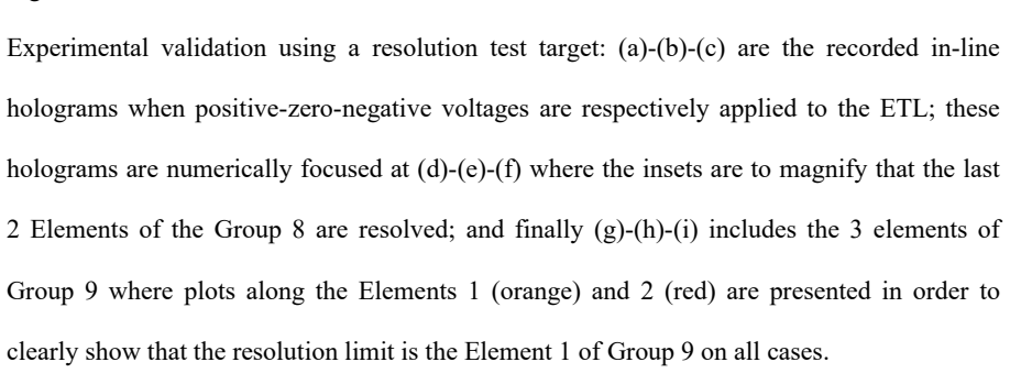
The paper reports variable-zoom digital in-line holographic microscopy (VZ-DIHM): an ETL placed before the focusing lens changes the optical power of the illumination path, effectively shifting the point source by a small axial distance $\Delta z$ and thereby changing the geometric magnification $M=(z+d)/z$, where $z$ is the source-to-sample distance and $d$ is the sample-to-sensor distance. With the ETL driven at $+6$D, $0$D, and $-2$D, the measured magnification changes from 15.6X to 25.9X to 35.4X, while the field of view shrinks from $360\times270\ \mu\text{m}^2$ to $159\times119\ \mu\text{m}^2$; these values are reported to be in good agreement with the theoretical predictions of 15.4X, 26X, and 34.8X. The resolution limit stays at about 1.95 $\mu$m (Element 1 of Group 9 on the USAF target), unchanged by the zoom because the numerical aperture is set by the sensor geometry rather than the source position. Phase images of prostate cancer cells show quantitative phase values comparable to those from a conventional DHM platform, and the background phase standard deviation with the ETL at 0D (0.0023 rad) is reported as indicating no substantial degradation relative to the no-ETL case (0.00024 rad).
Load-bearing premise
The computed magnification values rely on the manufacturer's rated ETL powers (-2, 0, and +6 diopters) and on treating the tunable lens and the focusing lens as thin lenses at the same axial location, an assumption the paper itself notes is only approximate.
Editorial extensions
If this is right
- The same physical layout, with no mechanical adjustments, can switch between a wide-field overview at about 15X and a magnified close-up at about 35X, and any setting in between.
- The maximum-to-minimum magnification ratio is 2.26, which changes the total field of view by a factor of about 5; the shorter the source-to-sample distance, the larger this zoom ratio.
- The resolution limit stays at about 1.95 $\mu$m across the zoom range, because the NA is set by the sample-to-sensor distance and the sensor size, not by the illumination source position.
- Quantitative phase imaging of biological samples is preserved: prostate cancer cells reconstructed with the ETL show phase values comparable to those from a conventional DHM setup.
- The same approach can support higher zoom ranges with ETLs of larger dioptric swing, such as models spanning $-10$D to $+10$D.
Reading between the lines
- Because the $\Delta z$ shift is sub-millimetre, the ETL is effectively a fast, vibration-free axial stage for the illumination source; this could be used for rapid refocusing or depth scanning in DIHM, beyond the zoom application demonstrated.
- Since the zoom ratio grows as $z$ shrinks, the benefit of this approach is strongest in DIHM geometries with the source very close to the sample; in on-chip geometry, where the sample is close to the sensor and the source is far, the effect would nearly vanish.
- A direct test of the coma hypothesis would be to remeasure the background phase STD with the ETL mounted horizontally; if the one-order-of-magnitude difference from the no-ETL case disappears, vertical gravity sag, not the ETL optics, is responsible.
- Calibrating the ETL's actual dioptric power at each voltage with a separate beam measurement would turn Eq. (2) from an approximation into a predictive design tool, and would quantify how much of the measured 15.6X, 25.9X, and 35.4X values depends on the assumed lens parameters.
Editorial analysis
A structured set of objections, weighed in public.
Referee Report
Summary. The paper proposes inserting an electrically tunable lens (ETL) into a digital in-line holographic microscopy (DIHM) layout immediately before the focusing lens that creates the illumination point source. Changing the ETL optical power shifts the source axial position, thereby changing the geometric magnification M = (z+d)/z and the field of view without any mechanical movement. An approximate formula for the source shift Δz is given, and the idea is validated with a USAF 1951 target at three ETL states (6D, 0D, -2D), yielding measured magnifications of 15.6X, 25.9X, and 35.4X, a resolution limit of 1.95 µm, and a magnification ratio of 2.26. The approach is also demonstrated on prostate cancer cells, including quantitative phase imaging, with a background phase STD comparison with and without the ETL.
Significance. The central experimental observation—that an ETL can electronically change the magnification of a lensless inline holographic microscope—is credible and directly measured, with no free parameters in the geometric model. The USAF-target magnifications (15.6X, 25.9X, 35.4X) agree with the geometric prediction (15.4X, 26X, 34.8X) at the ~1% level, and demonstrating the effect on a biological sample strengthens the practical case. The proposed addition of a single ETL is a simple and useful extension of earlier lensless-microscopy work. However, the abstract's quantitative range (15–35X) and the 'continuous variation' claim are extrapolated from three discrete ETL states, and the theoretical curve depends on a garbled equation and on uncalibrated manufacturer-rated ETL powers. These issues are local and correctable, and do not undermine the existence of the zoom effect itself.
major comments (4)
- [Section 2, Eq. (2)] As printed, Eq. (2) cannot reproduce the quoted Δz values. For the 6D case the text gives f'ETL = 166.67 mm and Δz ≈ 0.366 mm; this is consistent with Δz = f'FL^2/f'ETL (for f'FL ≈ 7.8 mm), not with the printed expression Δz = f'FL^2/f'ETL + f'FL, which would give an order-of-magnitude larger value. Moreover, f'FL is never stated in the text, and the following sentence refers to 'TL' instead of 'ETL'. Please correct the equation, define f'FL, and provide its value, since the theoretical curve in Fig. 3(a) is computed from Δz.
- [Section 3.1, Table 1 and Fig. 3(a)] The 'perfect agreement' between the measured magnifications and the geometric curve is asserted without an uncertainty budget. The ETL optical powers are taken from the manufacturer's -2D, 0D, +6D labels rather than from in-situ calibration, and Eq. (2) is explicitly approximate (thin-lens, co-located ETL and FL). A 0.5D error in the ETL power, a few tens of micrometres in ETL–FL separation, or a 1% uncertainty in z or d would shift Δz by tens of micrometres and change the predicted M by roughly 1X. Please report uncertainties on M, Δz, and the measured FOV values, and, if possible, calibrate the ETL optical power in the actual layout.
- [Section 4 and Abstract] The claim of 'continuous variation' of magnification and FOV is supported by only three discrete ETL states. The paper demonstrates ETL at 6D, 0D, and -2D; the continuous zoom curve in Fig. 3(a) is a theoretical interpolation, not a measurement. To substantiate the 'variable zoom' claim in the title and abstract, please provide at least a few intermediate ETL drive currents or voltages (or a continuous sweep of M versus ETL control) showing that the magnification varies monotonically and controllably between the endpoints.
- [Section 3.2, Figs. 4(c)-(h) and Fig. 5] The phase-validation comparison reports a background STD of 0.0023 rad with the ETL at 0D and 0.00024 rad without the ETL—an order-of-magnitude difference. The text attributes this to coma from vertical ETL mounting and then concludes that no significant phase variation is induced by the ETL. That conclusion is not fully supported by the reported numbers. Additionally, the SMIM DHM comparison in Fig. 5 uses a different set of cells from a different region of the sample, so it does not directly validate the phase values of the same cells shown in Fig. 4. Please either quantify the coma-induced phase error at the cell location or soften the conclusion to state that background phase stability is degraded when the ETL is present, but the cell-phase values remain comparable.
minor comments (6)
- [Section 3.1, NA calculation] The NA expression uses '(2.560x2.2)', which appears to be a typographical error; using the sensor half-width of 2.816 mm (2560×2.2 µm / 2) gives NA ≈ 0.22. Please correct the expression for clarity.
- [Figure 4 caption and related text] The caption lists '(g)-(f)' for the background phase distributions; this should read '(g)-(h)'. The same typo appears in the main text.
- [References] References 14 and 43 refer to the same paper (Sci Rep 2017;7:43291); the duplicate should be removed or cross-referenced.
- [Reference 33] Reference 33 lists 'Hankbook of holographic interferometry'; the correct spelling is 'Handbook'.
- [Section 4] The summary sentence 'we have reported on VZ-DIH' should read 'VZ-DIHM'.
- [Section 1] The phrase 'without neither replacement nor mechanical movement' is ungrammatical; consider 'without replacement or mechanical movement'.
Circularity Check
No significant circularity: the magnification model is independent of the measured USAF values, and the self-cited reconstruction and phase-validation tools are not load-bearing for the zoom claim.
full rationale
The paper's central claim is that an electrically tunable lens shifts the effective illumination source position and thereby changes DIHM magnification and field of view. The derivation chain is independent: Eq. (1) defines geometric magnification M=(z+d)/z from the measured distances z and d; Eq. (2) estimates the ETL-induced source shift from nominal ETL diopters and the focusing-lens focal length; and the experimental magnifications in Table 1 (15.6X, 25.9X, 35.4X) are measured directly from known USAF target features, not extracted from the model. The theoretical curve in Fig. 3(a) is therefore a genuine prediction rather than a fit, and no fitted parameter is renamed as a prediction. The paper explicitly acknowledges that Eq. (2) is approximate and that vertical ETL mounting may introduce coma (Secs. 2 and 4), but these are accuracy limitations, not circular reductions. The self-citations to MISHELF and SMIM work ([13,14,22,38]) are used as prior methodology or for an external phase-validation comparison, and they do not supply the zoom evidence; the phase comparison is corroborative only. Consequently the central zoom demonstration is self-contained and externally falsifiable against direct target measurements.
Assumptions & free parameters
assumptions (5)
- domain assumption Geometric magnification model M = (z+d)/z
- domain assumption Thin-lens, co-located lens model for the ETL and focusing lens (Eq. 2)
- standard math Rayleigh-Sommerfeld convolution propagation is an exact numerical model
- domain assumption Resolution limit ρ = λ/NA and NA from detector geometry
- domain assumption ETL optical power is given by the manufacturer-rated values at the applied voltages
Cite this review
Pith. "Pith review of Variable zoom digital in-line holographic microscopy." pith.science (2026). https://pith.science/paper/TRR5QKHF
@misc{pith2026250109570,
  author       = {Pith},
  title        = {Pith review of: Variable zoom digital in-line holographic microscopy},
  year         = {2026},
  howpublished = {\url{https://pith.science/paper/TRR5QKHF}},
  note         = {Machine review of arXiv:2501.09570}
}
read the original abstract
We report on a novel layout providing variable zoom in digital in-line holographic microscopy (VZ-DIHM). The implementation is in virtue of an electrically tunable lens (ETL) which enables to slightly shift the illumination source axial position without mechanical movement of any system component. Magnifications ranging from 15X to 35X are easily achievable using the same layout and resulting in a substantial variation of the total field of view (FOV). The performance of the proposed setup is, first, validated using a resolution test target where the main parameters are analyzed (theoretically and experimentally) and, second, corroborated analyzing biological sample (prostate cancer cells) showing its application to biomedical imaging.
Figures


Figures from the paper (2 more)


Reference graph
Works this paper leans on
-
[1]
Imaging without lenses: achievements and remaining challenges of wide- field on -chip microscopy
Greenbaum A, Luo W, Su T -W, Göröcs Z, Xue L, Isikman SO, et al. Imaging without lenses: achievements and remaining challenges of wide- field on -chip microscopy. Nat Methods 2012;9:889–95. doi:10.1038/nmeth.2114
-
[2]
Ozcan A, McLeod E. Lensless Imaging and Sensing. Annu Rev Biomed Eng 2016;18:77–
work page 2016
-
[3]
Unconventional methods of imaging: computational microscopy and compact implementations
McLeod E, Ozcan A. Unconventional methods of imaging: computational microscopy and compact implementations. Rep Prog Phys 2016;79:076001. doi:10.1088/0034- 4885/79/7/076001
doi:10.1088/0034- 2016
-
[4]
Wu Y, Ozcan A. Lensless digital holographic microscopy and its applications in biomedicine and environmental monitoring. Methods 2018;136:4–16. doi:10.1016/j.ymeth.2017.08.013
-
[5]
Gabor D. A New Microscopic Principle. Nature 1948;161:777–8. doi:10.1038/161777a0
-
[6]
XIV.—Experiments in Diffraction Microscopy
Rogers GL. XIV.—Experiments in Diffraction Microscopy. Proc R Soc Edinb Sect Math Phys Sci 1952;63:193–221. doi:10.1017/S0080454100007093
-
[7]
Digital in -line holography for biological applications
Xu W, Jericho MH, Meinertzhagen IA, Kreuzer HJ. Digital in -line holography for biological applications. Proc Natl Acad Sci 2001;98:11301–5. doi:10.1073/pnas.191361398
-
[8]
Lensless digital holographic microscope with light - emitting diode illumination
Repetto L, Piano E, Pontiggia C. Lensless digital holographic microscope with light - emitting diode illumination. Opt Lett 2004;29:1132. doi:10.1364/OL.29.001132
Show all 54 references
-
[10]
Microbial population dynamics by digital in- line holographic microscopy
Frentz Z, Kuehn S, Hekstra D, Leibler S. Microbial population dynamics by digital in- line holographic microscopy. Rev Sci Instrum 2010;81:084301. doi:10.1063/1.3473937. 19
2010 doi
-
[11]
Lensless multispectral digital in -line holographic microscope
Ryle JP, McDonnell S, Sheridan JT. Lensless multispectral digital in -line holographic microscope. J Biomed Opt 2011;16:126004. doi:10.1117/1.3659681
2011 doi
-
[12]
Color lensless digital holographic microscopy with micrometer resolution
Garcia-Sucerquia J. Color lensless digital holographic microscopy with micrometer resolution. Opt. Lett. 2012;37:1724-6. doi.org/10.1364/OL.37.001724
2012 doi
-
[13]
Improved quantitative phase imaging in lensless microscopy by single- shot multi -wavelength illumination using a fast convergence algorithm
Sanz M, Picazo-Bueno JA, García J, Micó V. Improved quantitative phase imaging in lensless microscopy by single- shot multi -wavelength illumination using a fast convergence algorithm. Opt Express 2015;23:21352. doi:10.1364/OE.23.021352
2015 doi
-
[15]
Ultra wide- field lens -free monitoring of cells on -chip
Ozcan A, Demirci U. Ultra wide- field lens -free monitoring of cells on -chip. Lab Chip 2008;8:98–106. doi:10.1039/B713695A
2008 doi
-
[16]
Multi -color LUCAS: Lensfree On -chip Cytometry Using Tunable Monochromatic Illumination and Digital Noise Reduction
Seo S, Su T -W, Erlinger A, Ozcan A. Multi -color LUCAS: Lensfree On -chip Cytometry Using Tunable Monochromatic Illumination and Digital Noise Reduction. Cell Mol Bioeng 2008;1:146–56. doi:10.1007/s12195-008-0018-6
2008 doi
-
[18]
Laser Light-field Fusion for Wide-field Lensfree On-chip Phase Contrast Microscopy of Nanoparticles
Kazemzadeh F, Wong A. Laser Light-field Fusion for Wide-field Lensfree On-chip Phase Contrast Microscopy of Nanoparticles. Sci Rep 2016;6. doi:10.1038/srep38981
2016 doi
-
[19]
Dynamics of cell and tissue growth acquired by means of extended field of view lensfree microscopy
Momey F, Coutard J-G, Bordy T, Navarro F, Menneteau M, Dinten J -M, et al. Dynamics of cell and tissue growth acquired by means of extended field of view lensfree microscopy. Biomed Opt Express 2016;7:512. doi:10.1364/BOE.7.000512
2016 doi
-
[20]
Reconstruction of high- resolution holographic microscopic images
Kanka M, Riesenberg R, Kreuzer HJ. Reconstruction of high- resolution holographic microscopic images. Opt Lett 2009;34:1162. doi:10.1364/OL.34.001162. 20
2009 doi
-
[21]
High resolution (NA=08) in lensless in- line holographic microscopy with glass sample carriers
Kanka M, Riesenberg R, Petruck P, Graulig C. High resolution (NA=08) in lensless in- line holographic microscopy with glass sample carriers. Opt Lett 2011;36:3651. doi:10.1364/OL.36.003651
2011 doi
-
[22]
Dual -mode holographic microscopy imaging platform
Sanz M, Picazo -Bueno JA, García J, Micó V. Dual -mode holographic microscopy imaging platform. Lab Chip 2018;18:1105–12. doi:10.1039/C7LC01304C
2018 doi
-
[23]
Achieving magnification smaller than 1 in lensless microscopy by illumination with a convergent wavefront
Perraut F, Doménès M, Grateau H, Josso Q. Achieving magnification smaller than 1 in lensless microscopy by illumination with a convergent wavefront. Opt Lett 2016;41:5326. doi:10.1364/OL.41.005326
2016 doi
-
[24]
Quantitative phase imaging system with slightly-off-axis configuration and suitable for objects both larger and smaller than the size of the image sensor
Yang Y, Cheng Z -J, Zhao H-M, Yue Q-Y, Guo C-S. Quantitative phase imaging system with slightly-off-axis configuration and suitable for objects both larger and smaller than the size of the image sensor. Opt Express 2018;26:17199. doi:10.1364/OE.26.017199
2018 doi
-
[25]
Fast two- layer two-photon imaging of neuronal cell populations using an electrically tunable lens
Grewe BF, Voigt FF, van ’t Hoff M, Helmchen F. Fast two- layer two-photon imaging of neuronal cell populations using an electrically tunable lens. Biomed Opt Express 2011;2:2035. doi:10.1364/BOE.2.002035
2011 doi
-
[26]
Rapid 3D light -sheet microscopy with a tunable lens
Fahrbach FO, Voigt FF, Schmid B, Helmchen F, Huisken J. Rapid 3D light -sheet microscopy with a tunable lens. Opt Express 2013;21:21010. doi:10.1364/OE.21.021010
2013 doi
-
[27]
High- speed transport -of-intensity phase microscopy with an electrically tunable lens
Zuo C, Chen Q, Qu W, Asundi A. High- speed transport -of-intensity phase microscopy with an electrically tunable lens. Opt Express 2013;21:24060. doi:10.1364/OE.21.024060
2013 doi
-
[28]
Enhanced quantitative phase imaging in self-interference digital holographic microscopy using an electrically focus tunable lens
Schubert R, Vollmer A, Ketelhut S, Kemper B. Enhanced quantitative phase imaging in self-interference digital holographic microscopy using an electrically focus tunable lens. Biomed Opt Express 2014;5:4213. doi:10.1364/BOE.5.004213
2014 doi
-
[29]
Reconstruction method for extended d epth-of-field optical diffraction tomography
Krauze W, Kuś A, Śladowski D, Skrzypek E, Kujawińska M. Reconstruction method for extended d epth-of-field optical diffraction tomography. Methods 2018;136:40–9. doi:10.1016/j.ymeth.2017.10.005. 21
2018 doi
-
[30]
Synthetic aperture microscopy based on referenceless phase retrieval with an electrically tunable lens
Lee DJ, Han K, Lee HJ, Weiner AM. Synthetic aperture microscopy based on referenceless phase retrieval with an electrically tunable lens. Appl Opt 2015;54:5346. doi:10.1364/AO.54.005346
2015 doi
-
[31]
Simple and flexible phase compensation for digital holographic microscopy with electrically tunable lens
Deng D, Peng J, Qu W, Wu Y, Liu X, He W, et al. Simple and flexible phase compensation for digital holographic microscopy with electrically tunable lens. Appl Opt 2017;56:6007. doi:10.1364/AO.56.006007
2017 doi
-
[32]
All -optical microscope autofocus based on an electrically tunable lens and a totally internally reflected IR laser
Bathe-Peters M, Annibale P, Lohse MJ. All -optical microscope autofocus based on an electrically tunable lens and a totally internally reflected IR laser. Opt Express 2018;26:2359. doi:10.1364/OE.26.002359
2018 doi
-
[33]
Hankbook of holographic interferometry: optical and digital methods (Wiley - VCH, 2005)
Kreis T. Hankbook of holographic interferometry: optical and digital methods (Wiley - VCH, 2005)
2005
-
[34]
Fast numerical reconstruction technique for high- resolution hybrid holographic microscopy
Takaki Y, Ohzu H. Fast numerical reconstruction technique for high- resolution hybrid holographic microscopy. Appl Opt 1999;38:2204. doi: 10.1364/AO.38.002204
1999 doi
-
[35]
Digital holography and digital image processing: principles, methods, algorithms (Kluwer, 2003)
Yaroslavsky LP. Digital holography and digital image processing: principles, methods, algorithms (Kluwer, 2003)
2003
-
[36]
Automatic method for focusing biological specimens in digital lensless holographic microscopy
Trujillo CA, Garcia-Sucerquia J. Automatic method for focusing biological specimens in digital lensless holographic microscopy. Opt Lett 2014;39:2569. doi: 10.1364/OL.39.002569
2014 doi
-
[37]
Refocus criterion for both phase and amplitude objects in digital holographic microscopy
Dubois F, El Mallahi A, Dohet -Eraly J, Yourassowsky C. Refocus criterion for both phase and amplitude objects in digital holographic microscopy. Opt Lett 2014;39:4286. doi: 10.1364/OL.39.004286
2014 doi
-
[38]
Single -shot slightly off- axis digital holographic microscopy with add-on module based on beamsplitter cube
Picazo-Bueno JA, Trusiak M, Micó V. Single -shot slightly off- axis digital holographic microscopy with add-on module based on beamsplitter cube. Opt Express 2019;27:5655. doi:10.1364/OE.27.005655. 22
2019 doi
-
[39]
Optical imaging techniques for point-of-care diagnostics
Zhu H, Isikman SO, Mudanyali O, Greenbaum A, Ozcan A. Optical imaging techniques for point-of-care diagnostics. Lab Chip 2019;13:51-56. doi: 10.1039/c2lc40864c
2019 doi
-
[40]
Imaging of dense cell cultures by multiwavelength lens- free video microscopy: Cell Cultures by Lens-Free Microscopy
Allier C, Morel S, Vincent R, Ghenim L, Navarro F, Menneteau M, et al. Imaging of dense cell cultures by multiwavelength lens- free video microscopy: Cell Cultures by Lens-Free Microscopy. Cytometry A 2017;91:433–42. doi: 10.1002/cyto.a.23079
2017 doi
-
[41]
High- throughput lensfree imaging and characterization of a heterogeneous cell solution on a chip
Su T- W, Seo S, Erlinger A, Ozcan A. High- throughput lensfree imaging and characterization of a heterogeneous cell solution on a chip. Biotechnol Bioeng 2009;102:856–68. doi: 10.1002/bit.22116
2009 doi
-
[42]
Field -portable lensfree tomographic microscope
Isikman SO, Bishara W, Sikora U, Yaglidere O, Yeah J, Ozcan A. Field -portable lensfree tomographic microscope. Lab Chip 2011;11:2222. doi: 10.1039/c1lc20127a
2011 doi
-
[43]
Compact, cost -effective and field -portable microscope prototype based on MISHELF microscopy
Martín Sanz, José Ángel Picazo -Bueno, Luis Granero, Javier García, Vicente Micó. Compact, cost -effective and field -portable microscope prototype based on MISHELF microscopy. Sci Rep 2017;7:43291. doi: 10.1038/srep43291
2017 doi
-
[44]
High- throughput monitoring of major cell functions by means of lensfree video microscopy
Kesavan SV, Momey F, Cioni O, David- Watine B, Dubrulle N, Shorte S, et al. High- throughput monitoring of major cell functions by means of lensfree video microscopy. Sci Rep 2015;4. doi: 10.1038/srep05942
2015 doi
-
[45]
Submersible digital in- line holographic microscope
Jericho SK, Garcia-Sucerquia J, Xu W, Jericho MH, Kreuzer HJ. Submersible digital in- line holographic microscope. Rev Sci Instrum 2006;77:043706. doi: 10.1063/1.2193827
2006 doi
-
[46]
Imaging and Identification of Waterborne Parasites Using a Chip -Scale Microscope
Lee SA, Erath J, Zheng G, Ou X, Willems P, Eichinger D, et al. Imaging and Identification of Waterborne Parasites Using a Chip -Scale Microscope. PLoS ONE 2014;9:e89712. doi: 10.1371/journal.pone.0089712
2014 doi
-
[47]
Development and deployment of a point-source digital inline holographic microscope for the study of plankton and particles to a depth of 6000 m: Deep- sea holographic microscopy
Bochdansky AB, Jericho MH, Herndl GJ. Development and deployment of a point-source digital inline holographic microscope for the study of plankton and particles to a depth of 6000 m: Deep- sea holographic microscopy. Limnol Oceanogr Methods 2013;11:28–40. doi: 10.4319/lom.2013...
2013 doi
-
[48]
In -line digital holographic microscopy for terrestrial and exobiological research
Jericho SK, Klages P, Nadeau J, Dumas EM, Jericho MH, Kreuzer HJ. In -line digital holographic microscopy for terrestrial and exobiological research. Planet Space Sci 2010;58:701–5. doi: 10.1016/j.pss.2009.07.012
2010 doi
-
[49]
Tracking particles in four dimensions with in-line holographic microscopy
Xu W, Jericho MH, Kreuzer HJ, Meinertzhagen IA. Tracking particles in four dimensions with in-line holographic microscopy. Opt Lett 2003;28:164. doi: 10.1364/OL.28.000164
2003 doi
-
[50]
Recent advances in holographic 3D particle tracking
Memmolo P, Miccio L, Paturzo M, Caprio GD, Coppola G, Netti PA, et al. Recent advances in holographic 3D particle tracking. Adv Opt Photonics 2015;7:713. doi: 10.1364/AOP.7.000713
2015 doi
-
[51]
Compact, lensless digital holographic microscope for remote microbiology
Serabyn E, Liewer K, Lindensmith C, Wallace K, Nadeau J. Compact, lensless digital holographic microscope for remote microbiology. Opt Express 2016;24:28540. doi: 10.1364/OE.24.028540
2016 doi
-
[52]
High-throughput lensfree 3D tracking of human sperms reveals rare statistics of helical trajectories
Su T-W, Xue L, Ozcan A. High-throughput lensfree 3D tracking of human sperms reveals rare statistics of helical trajectories. Proc Natl Acad Sci 201 2;109:16018–22. doi: 10.1073/pnas.1212506109
-
[53]
Sperm Trajectories Form Chiral Ribbons
Su T-W, Choi I, Feng J, Huang K, McLeod E, Ozcan A. Sperm Trajectories Form Chiral Ribbons. Sci Rep 2013;3. doi: 10.1038/srep01664
2013 doi
-
[54]
Cost -effective and compact wide- field fluorescent imaging on a cell- phone
Zhu H, Yaglidere O, Su T -W, Tseng D, Ozcan A. Cost -effective and compact wide- field fluorescent imaging on a cell- phone. Lab Chip 2011;11:315–22. doi: 10.1039/C0LC00358A
2011 doi
-
[55]
A smartphone -based fluorescence microscope utilizing an external phone camera lens module
Kim J -H, Joo H -G, Kim T -H, Ju Y -G. A smartphone -based fluorescence microscope utilizing an external phone camera lens module. BioChip J 2015;9:285–92. doi: 10.1007/s13206-015-9403-0
2015 doi
-
[56]
Tomography by point source digital holographic microscopy
Remacha C, Nickerson BS, Kreuzer HJ. Tomography by point source digital holographic microscopy. Appl Opt 2014;53:3520. doi: 10.1364/AO.53.003520. 24 FIGURE CAPTIONS Figure 1. Optical layout for the proposed variable magnification DIHM. CL, condenser lens; ETL, electrically tun...
2014 doi
-
[102]
doi:10.1146/annurev-bioeng-092515-010849
Reviewed August 10, 2026 · model on record in the stance chip above.
Discussion (0). Continue with ORCID to comment.