REVIEW 4 major objections 4 minor 25 references
UAV Communications: Impact of Obstacles on Channel Characteristics
T0 review · 4 major / 4 minor · reviewed 2026-08-11 · deepseek-v4-flash
Pith's one-line read This paper claims that inserting a building between a UAV-mounted Wi-Fi access point and a ground user cuts throughput from 51.8 to 41.5 Mbit/s and raises delay from 6.6 to 10.5 ms, and that moving the UAV to an unobstructed spot restores…
desk verdict Confounded propagation-model comparison and an impossible guard interval undermine an otherwise unremarkable ns-3 demonstration. read the letter →
The pith
A machine-rendered reading of the paper's core claim, the machinery that carries it, and where it could break.
The reading
What carries the argument
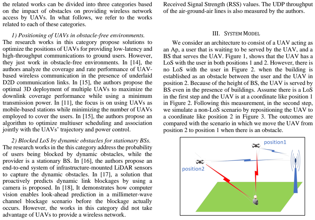
The central machinery is the pair of propagation-loss models in the ns-3 simulator: the Friis free-space path-loss model for the obstacle-free scenario and the HybridBuildingsPropagationLossModel for the obstacle scenario, the latter adding building-dependent attenuation and shadowing to the same 5 GHz Wi-Fi link. The building block is a rectangular obstacle with coordinates x_min=10, x_max=20, y_min=0, y_max=50, z_min=-30, z_max=30, and the UAV moves between position 1 (30,0,10) and position 2 behind the building. These models carry the argument by producing the throughput, delay, and delivery metrics that are compared across the obstructed and unobstructed configurations.
What would settle it
Run the same scenario in the simulator with the building present but with its attenuation set to zero while keeping all other parameters; if throughput and delay do not return to the unobstructed values, the reported degradation comes from the obstacle attenuation model. Conversely, a field test with a small UAV at 10 m altitude, 30 m horizontal distance, and a building between it and a 5 GHz ground client would show whether a roughly 20% throughput drop and a 4 ms delay increase actually occur.
Extended reading notes
Core claim
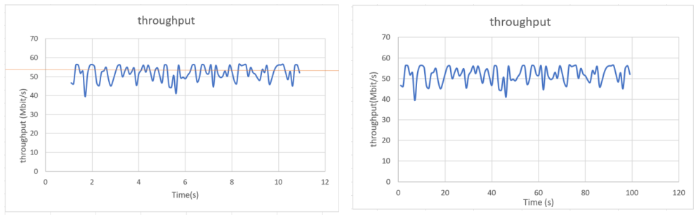
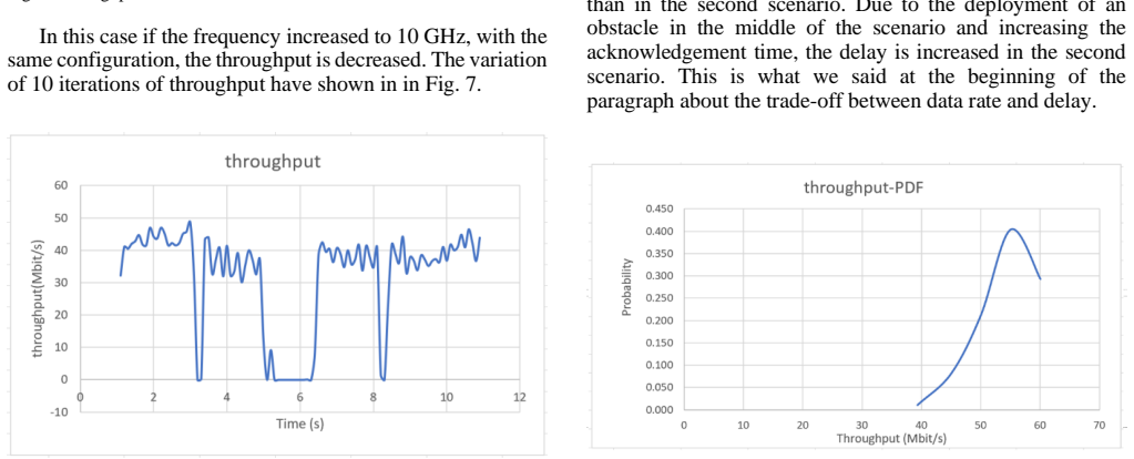
In this paper's terms, the central discovery is that a single static obstacle placed in an air-to-ground Wi-Fi link measurably degrades channel quality, and that repositioning the UAV to re-establish line of sight recovers that quality. The claim is supported by ns-3 simulations at 5 GHz: with the Friis propagation loss model and no obstacle, average throughput is 51.819 Mbit/s and end-to-end delay is 6.61881 ms; with HybridBuildingsPropagationLossModel and a building spanning x=10–20 m, y=0–50 m, z=±30 m, throughput falls to 41.5377 Mbit/s and delay rises to 10.5386 ms, while PDR remains 99% and packet loss remains 1%. The paper further reports that raising the frequency to 10 GHz under the same configuration decreases throughput further, and that relocating the access point to the original unobstructed position restores performance. The intended conclusion is that channel characterization for UAV links should include obstacles, and UAV placement should treat line-of-sight as a primary optimization criterion.
Load-bearing premise
The load-bearing premise is that the simulator's building attenuation model, as configured here, captures how a real building blocks a 5 GHz signal; if the configuration is unrealistic, the measured throughput drop may be a simulation artifact rather than a real obstacle effect.
Editorial extensions
If this is right
- If the claim is correct, UAV placement algorithms should treat line of sight as a first-class optimization target, not just coverage radius or user density.
- Obstacle-aware repositioning is a workable recovery mechanism: in this scenario, moving the access point from the blocked position back to the unobstructed position restores the original throughput and delay values.
- Carrier frequency strengthens the effect: the paper's 10 GHz run shows throughput falling further below the 5 GHz obstructed case, so obstacle awareness should matter more for higher-frequency air-to-ground links.
- Channel characterization for aerial links should routinely report both line-of-sight and non-line-of-sight configurations, because throughput and delay are strongly configuration-dependent.
Reading between the lines
- Going beyond the paper, the roughly 20% throughput penalty could be used as a simple scalar objective for obstacle-aware placement: maximize the fraction of users with clear line of sight to the UAV, and the QoS metrics should follow.
- A testable extension is to vary the building's height, width, and horizontal offset; one would predict that throughput degradation grows as the building increasingly blocks the direct path, with a threshold above which packet delivery ratio begins to fall.
- The setup could also be extended to multiple UAVs or moving blockers; a natural prediction is that blockage recovery time, rather than steady-state throughput, becomes the dominant QoS factor when obstacles move.
Signed reviews
Editorial analysis
A structured set of objections, weighed in public.
Referee Report
Summary. The paper proposes a simulation-based study of an air-to-ground Wi-Fi link between a UAV-mounted access point and a ground user in ns-3. It compares an obstacle-free scenario using the Friis propagation loss model with an obstacle scenario using the HybridBuildingsPropagationLossModel, reporting average throughput, PDR, packet loss, and end-to-end delay over 10 runs. The authors claim that placing a building between the UAV and the user degrades QoS and that moving the UAV to a line-of-sight position restores performance. They position the work as an obstacle-aware channel characterization and as a step toward obstacle-aware UAV positioning.
Significance. If the claims were established, the paper would provide a modest simulation-based confirmation that 5 GHz air-to-ground links degrade when a building blocks line of sight and that repositioning recovers performance. The paper has some strengths: the simulation parameters are listed in tables, and the use of 10 repeated runs is better than a single run. However, the central comparison conflates the propagation model with the presence of the obstacle, the reported statistics lack any uncertainty measure, and a listed Wi-Fi guard interval of 100 ms is physically implausible for 802.11ac. As written, the result is largely a demonstration of ns-3's built-in building attenuation rather than an independent characterization of air-to-ground channels, so its significance for the UAV placement literature is currently limited.
major comments (4)
- [Section IV-A and IV-C] The obstacle-free and obstacle scenarios differ in two variables at once: the presence of the building and the propagation loss model. Scenario 1 uses the Friis path loss model, while scenario 2 uses HybridBuildingsPropagationLossModel. No control run with HybridBuildingsPropagationLossModel and an empty scene is reported. The observed drop in average throughput from 51.819 to 41.5377 Mbit/s and the increase in delay from 6.61881 to 10.5386 ms are therefore not causally attributable to the obstacle. This is load-bearing because the paper's conclusion rests on attributing the QoS change to the building. A control experiment with the same propagation model and the building present/absent, or an otherwise identical setup using one propagation model, is needed before the central claim can be evaluated.
- [Section IV-C and Tables I-II] The paper reports averages over 10 simulation runs but provides no standard deviations, confidence intervals, per-run values, or distribution plots for the main metrics. Without a measure of run-to-run variability, the reported differences in throughput and delay cannot be distinguished from simulation noise. The authors should report variance or confidence intervals, and ideally show per-run data or box plots, to support the quantitative comparison.
- [Tables I and II] The guard interval is listed as 100 ms. In 802.11ac OFDM, guard intervals are on the order of 0.4 to 3.2 microseconds, so 100 ms is not a physically valid parameter and suggests a unit or configuration error. This parameter undermines the fidelity of the reported results. The authors must correct the guard interval to a standard 802.11ac value and rerun the simulations, or explicitly justify why 100 ms was used.
- [Sections I, V, and VI] The central claim is substantially overstated relative to the evidence. A single static scenario with one building, one ground user, and one frequency band is used to support a broad conclusion about UAV positioning with obstacles improving QoS and coverage. Moreover, since HybridBuildingsPropagationLossModel is specifically designed to add building attenuation, the simulation outcome largely restates the model's assumptions rather than providing an independent empirical characterization. The paper should be reframed as a demonstration of an ns-3 simulation workflow, with the scope clearly limited to this scenario, or it should include additional scenarios and a validation discussion.
minor comments (4)
- [Figures 4-8] The figure captions contain repeated typos and are internally inconsistent: 'Throghput' appears in several captions, Fig. 8 is captioned as a probability distribution function but appears to show a throughput time series, and Section VI refers to a 'Fig. 9' that does not exist.
- [Tables I and II] Table II omits the packet size row that is present in Table I, so the two listed configurations are not fully comparable as presented. The table headers also misspell 'SCERARIO'.
- [Section I] The statement that obstacle-aware UAV repositioning 'has not been investigated so far' is contradicted by the paper's own references, including [1], [2], and [22]. The novelty claim should be softened and positioned relative to those works.
- [Abstract and Section IV-B] There are typographical issues such as 'Th e' in the abstract and 'Tthroughput' in the metrics list. These should be corrected for readability.
Circularity Check
Obstacle effect is pre-encoded: switching from Friis to HybridBuildingsPropagationLossModel makes the QoS drop a model output, not a measured discovery.
-
self definitional
[Section IV-A (Simulation Setup), Section IV-C (Simulation Results), and Section VI (Main Conclusions)]
"We employed the Friis propagation loss model in an obstacle-free scenario and a hybrid building pr opagation loss model in case we had obstacles in the scenario. ... In the second scenario, where F = 5GHz, and we have deployed the building as an obstacle, the obtained throughput has decreased and the delay has increased. The average throughput in this case was 41.5377 Mbit/s ... and the end-to-end delay was 10.5386 ms."
The first scenario uses Friis (free-space) loss; the second uses HybridBuildingsPropagationLossModel, an ns-3 model specifically designed to add building-dependent losses. Inserting a building into that model necessarily produces attenuation, so the observed throughput drop (51.819 to 41.5377 Mbit/s) and delay increase (6.61881 to 10.5386 ms) are direct outputs of the model's built-in rules. The two scenarios differ in both the obstacle and the propagation model, and no control run with HybridBuildingsPropagationLossModel and an empty scene is reported. The conclusion that obstacles degrade QoS and that LoS repositioning restores it is therefore a restatement of the simulator's geometric blockage logic, not an independent measurement.
full rationale
This paper is a simulation study rather than a mathematical derivation, so the usual circularity tests must be applied to the inference from simulation configuration to conclusion. The central claim—that placing a building between UAV and UE degrades throughput and delay, and that moving to LoS restores performance—is supported only by comparing a Friis-model scenario against a HybridBuildingsPropagationLossModel scenario. Because HybridBuildingsPropagationLossModel is defined to attenuate signals when buildings obstruct the path, the simulated degradation is a tautological consequence of the chosen model; the absence of a same-model, no-building control means the building's marginal effect is never isolated. The self-citations in the reference list are background/related-work citations and are not load-bearing, so they do not independently raise the score. The central result reduces to the simulator's built-in behavior, giving a circularity score of 6 rather than 0-2. A non-circular version would use the same propagation model with and without the obstacle, or validate against real channel measurements.
Assumptions & free parameters
free parameters (4)
- UAV altitude =
10 m
- Building footprint =
x 10-20, y 0-50, z -30 to 30
- Guard interval =
100 ms
- Carrier frequency =
5 GHz and 10 GHz
assumptions (4)
- domain assumption ns-3's Friis and HybridBuildingsPropagationLossModel accurately model 5 GHz air-to-ground propagation.
- domain assumption The building fully blocks line of sight in the NLoS scenario and no diffracted or reflected path is material.
- ad hoc to paper The listed simulation parameters are physically valid and consistent.
- domain assumption Ten simulation runs of an ns-3 scenario are sufficient to report averages without variance.
Cite this review
Pith. "Pith review of UAV Communications: Impact of Obstacles on Channel Characteristics." pith.science (2026). https://pith.science/paper/UO7B6LEG
@misc{pith2026241217934,
  author       = {Pith},
  title        = {Pith review of: UAV Communications: Impact of Obstacles on Channel Characteristics},
  year         = {2026},
  howpublished = {\url{https://pith.science/paper/UO7B6LEG}},
  note         = {Machine review of arXiv:2412.17934}
}
read the original abstract
In recent years, Unmanned Aerial Vehicles (UAVs) have been utilized as effective platforms for carrying Wi-Fi Access Points (APs) and cellular Base Stations (BSs), enabling low-cost, agile, and flexible wireless networks with high Quality of Service (QoS). The next generation of wireless communications will rely on increasingly higher frequencies, which are easily obstructed by obstacles. One of the most critical concepts yet to be fully addressed is positioning the UAV at optimal coordinates while accounting for obstacles. To ensure a line of sight (LoS) between UAVs and user equipment (UE), improve QoS, and establish reliable wireless links with maximum coverage, obstacles must be integrated into the proposed placement algorithms. This paper introduces a simulation-based measurement approach for characterizing an air-to-ground (AG) channel in a simple scenario. By considering obstacles, we present a novel perspective on channel characterization. The results, in terms of throughput, packet delivery, packet loss, and delay, are compared using the proposed positioning approach.
Figures


Figures from the paper (3 more)

Reference graph
Works this paper leans on
-
[1]
Autonomous Vision -Aided UAV Positioning for Obstacle -Aware Wireless Connectivity,
K. Shafafi, M. Ricardo, and R. Campos, "Autonomous Vision -Aided UAV Positioning for Obstacle -Aware Wireless Connectivity," arXiv preprint arXiv:2506.23190, 2025
-
[2]
A Framework to Develop and Validate RL -Based Obstacle -Aware UAV Positioning Algorithms,
K. Shafafi, M. Ricardo, and R. Campos, "A Framework to Develop and Validate RL -Based Obstacle -Aware UAV Positioning Algorithms," arXiv preprint arXiv:2502.08787, 2025
-
[3]
An Adaptive UAV Deployment Scheme for Emergency Networking,
L. Na, Y. Liu, L. Zhao, D. O. Wu, and Y. Wang, “An Adaptive UAV Deployment Scheme for Emergency Networking,” IEEE Trans. Wireless. Commun., vol. PP, no. NOVEMBER 2020, p. 1, 2021, doi: 10.1109/TWC.2021.3111991
arXiv 2020
-
[4]
Joint Traffic and Obstacle-Aware UAV Positioning Algorithm for Aerial Networks,
K. Shafafi, A. Coelho, R. Campos , and M. Ricardo, "Joint Traffic and Obstacle-Aware UAV Positioning Algorithm for Aerial Networks," 2023 IEEE 9th World Forum on Internet of Things (WF-IoT), Aveiro, Portugal, 2023, pp. 1-6, doi: 10.1109/WF-IoT58464.2023.10539557
-
[5]
UAV -assisted wireless communications: An experimental analysis of A2G and G2A channels
K. Shafafi, E. N. Almeida, A. Coelho, H. Fontes, M. Ricardo , and R. Campos, "UAV -assisted wireless communications: An experimental analysis of A2G and G2A channels" in Simulation Tools and Techniques, Cham, Switzerland: Springer, pp. 243-256, 2024
work page 2024
-
[6]
Wireless communications with unmanned aerial vehicles: Opportunities and challenges,
Y. Zeng, R. Zhang, and T. J. Lim, “Wireless communications with unmanned aerial vehicles: Opportunities and challenges,” IEEE Commun. Mag. , vol. 54, no. 5, pp. 36 –42, 2016, doi: 10.1109/MCOM.2016.7470933
arXiv 2016
-
[7]
Backhaul-aware robust 3D drone placement in 5G+ wireless networks,
E. Kalantari, M. Z. Shakir, H. Yanikomeroglu, and A. Yongacoglu, “Backhaul-aware robust 3D drone placement in 5G+ wireless networks,” 2017 IEEE Int. Conf. Commun. Work. ICC Work. 2017 , pp. 109 –114, 2017, doi: 10.1109/ICCW.2017.7962642
arXiv 2017
-
[8]
M. Alzenad, A. El -Keyi, and H. Yanikomeroglu, “3 -D Placement of an Unmanned Aerial Vehicle Base Station for Maximum Coverage of Users with Different QoS Requirements,” IEEE Wirel. Commun. Lett., vol. 7, no. 1, pp. 38–41, 2018, doi: 10.1109/LWC.2017.2752161
Show all 25 references
-
[9]
Multi - UAV Area Coverage Based on Relative Localization: Algorithms and Optimal UAV Placement,
Z. Zhang, X. Xu, J. Cui, W. Meng, S. Zhang, and B. Pradhan, “Multi - UAV Area Coverage Based on Relative Localization: Algorithms and Optimal UAV Placement,” 2021, doi: 10.3390/s21072400
2021 doi
-
[10]
Placement Optimization of UAV-Mounted Mobile Base Stations,
J. Lyu, Y. Zeng, R. Zhang, and T. J. Lim, “Placement Optimization of UAV-Mounted Mobile Base Stations,” IEEE Commun. Lett., vol. 21, no. 3, pp. 604–607, 2017, doi: 10.1109/LCOMM.2016.2633248
2017
-
[11]
3D Placement of a New Tethered UAV to UAV Relay System for Coverage Maximization,
J. Machado et al., “3D Placement of a New Tethered UAV to UAV Relay System for Coverage Maximization,” 2022, doi: 10.3390/electronics11030385
2022 doi
-
[12]
UAV positioning for throughput maximization,
S. Rahman and Y. Z. Cho, “UAV positioning for throughput maximization,” Eurasip J. Wirel. Commun. Netw., vol. 2018, no. 1, pp. 1– 15, Dec. 2018, doi: 10.1186/S13638-018-1038-0/TABLES/3
2018 doi
-
[13]
Unmanned Aerial Vehicle with Underlaid Device -to-Device Communications: Performance and Tradeoffs,
M. Mozaffari, W. Saad, M. Bennis, and M. Debbah, “Unmanned Aerial Vehicle with Underlaid Device -to-Device Communications: Performance and Tradeoffs,” IEEE Trans. Wirel. Commun., vol. 15, no. 6, pp. 3949–3963, 2016, doi: 10.1109/TWC.2016.2531652
2016
-
[14]
Efficient Deployment of Multiple Unmanned Aerial Vehicles for Optimal Wireless Coverage,
M. Mozaffari, W. Saad, M. Bennis, and M. Debbah, “Efficient Deployment of Multiple Unmanned Aerial Vehicles for Optimal Wireless Coverage,” IEEE Commun. Lett. , vol. 20, no. 8, pp. 1647 –1650, 2016, doi: 10.1109/LCOMM.2016.2578312
2016
-
[15]
Joint Trajectory and Communication Design for Multi-UAV Enabled Wireless Networks
Q. Wu, Y. Zeng, and R. Zhang, “Joint Trajectory and Communication Design for Multi-UAV Enabled Wireless Networks.”
-
[16]
LiDAR Aided Human Blockage Prediction for 6G,
D. Marasinghe, N. Rajatheva, and M. Latva-aho, “LiDAR Aided Human Blockage Prediction for 6G,” Oct. 2021, Accessed: Jan. 03, 2022. [Online]. Available: https://arxiv.org/abs/2110.00349v1
2021 arXiv
-
[17]
Vision -Aided Dynamic Blockage Prediction for 6G Wireless Communication Networks,
G. Charan, M. Alrabeiah, and A. Alkhateeb, “Vision -Aided Dynamic Blockage Prediction for 6G Wireless Communication Networks,” 2021 IEEE Int. Conf. Commun. Work. ICC Work. 2021 - Proc., pp. 1–6, 2021, doi: 10.1109/ICCWorkshops50388.2021.9473651
2021
-
[18]
When Wireless Communications Meet Computer Vision in beyond 5G,
T. Nishio, Y. Koda, J. Park, M. Bennis, and K. Doppler, “When Wireless Communications Meet Computer Vision in beyond 5G,” IEEE Commun. Stand. Mag. , vol. 5, no. 2, pp. 76 –83, 2021, doi: 10.1109/MCOMSTD.001.2000047
2021 doi
-
[19]
Multiple UAV- Borne IRS-Aided Millimeter Wave Multicast Communications: A Joint Optimization Framework,
K. Guo, C. Wang, Z. Li, D. W. K. Ng, and K. K. Wong, “Multiple UAV- Borne IRS-Aided Millimeter Wave Multicast Communications: A Joint Optimization Framework,” IEEE Commun. Lett. , vol. 25, no. 11, pp. 3674–3678, 2021, doi: 10.1109/LCOMM.2021.3111602
2021
-
[20]
Joint 3 -D Positioning and Power Allocation for UAV Relay Aided by Geographic Information,
P. Yi, L. Zhu, L. Zhu, Z. Xiao, Z. Han, and X. -G. Xia, “Joint 3 -D Positioning and Power Allocation for UAV Relay Aided by Geographic Information,” pp. 1 –14, 2021, [Online]. Available: http://arxiv.org/abs/2110.05715
2021 arXiv
-
[21]
Line-of- Sight Probability for mmWave -Based UAV Communications in 3D Urban Grid Deployments,
M. Gapeyenko, D. Moltchanov, S. Andreev, and R. W. Heath, “Line-of- Sight Probability for mmWave -Based UAV Communications in 3D Urban Grid Deployments,” IEEE Trans. Wirel. Commun. , vol. 20, no. 10, pp. 6566–6579, 2021, doi: 10.1109/TWC.2021.3075099
2021
-
[22]
Traffic and Obstacle -Aware UAV Positioning in Urban Environments Using Reinforcement Learning,
K. Shafafi, M. Ricardo and R. Campos, "Traffic and Obstacle -Aware UAV Positioning in Urban Environments Using Reinforcement Learning," in IEEE Access , vol. 12, pp. 188652 -188663, 2024, doi: 10.1109/ACCESS.2024.3515654
2024
-
[23]
Optimizing the Pictorial Compacted Data Detection Process for Working at the Noisy Environment, Using Reversible Symmetrical Codes,
K. Shafafi, A. Samanfar, E. Saremian, and O. Moradtalab, "Optimizing the Pictorial Compacted Data Detection Process for Working at the Noisy Environment, Using Reversible Symmetrical Codes," 2009 International Conference on Information and Multimedia Technology , Jeju, Korea (...
2009 doi
-
[24]
Joint Optimization of Multi-UAV Deployment and 3D Positioning in Traffic- Aware Aerial Networks,
K. Shafafi, A. A. Abdellatif, M. Ricardo, and R. Campos, "Joint Optimization of Multi-UAV Deployment and 3D Positioning in Traffic- Aware Aerial Networks," arXiv preprint arXiv:2506.13287, 2025
2025
-
[25]
PEL: Population -Enhanced Learning Classification for ECG Signal Analysis,
M. Pourvahab, S. J. Mousavirad, F. Lashgari, A. Monteiro, K. Shafafi, V. Felizardo, and S. Pais, "PEL: Population -Enhanced Learning Classification for ECG Signal Analysis," in *Advances in Optimization Algorithms for Multidisciplinary Engineering Applicati ons: From Classical...
2025 doi
Reviewed August 11, 2026 · model on record in the stance chip above.
Discussion (0). Continue with ORCID to comment.