REVIEW 3 major objections 5 minor 26 references
Empirical characterization of the Translational acoustic-RF communication channel
T0 review · 3 major / 5 minor · reviewed 2026-07-12 · grok-4.5
Pith's one-line read The underwater-to-air TARF channel does not follow classical fading models and is neither linear nor time-invariant.
desk verdict First solid GoF and residual tests on TARF amplitudes; mismatch and time-variance look real, but the linearity claim is confounded by unwrap and lacks isolation controls. read the letter →
The pith
A machine-rendered reading of the paper's core claim, the machinery that carries it, and where it could break.
The reading
What carries the argument
The refined surface-displacement integral that superposes acoustic arrivals along the radial path to each surface point, together with the pilot residual-error tests for linearity (weighted sum of identical pilots) and time-invariance (normalized pilot drift across successive OFDM symbols).
What would settle it
Repeat the identical OFDM pilot sequence in a larger, quieter basin with longer inter-symbol gaps and independent hydrophone surface measurements; if residual bias vanishes and pilot error no longer grows with symbol index, the non-linearity and time-variance claims fail.
Extended reading notes
Core claim
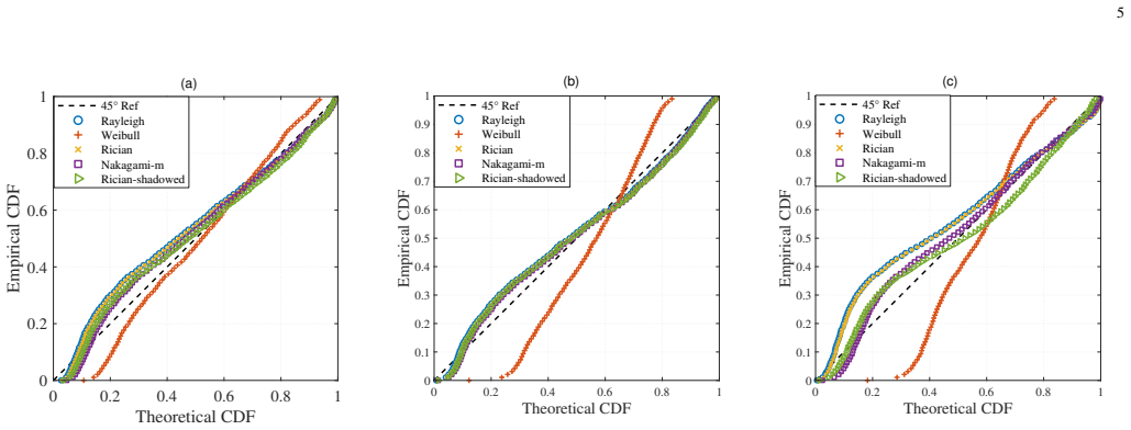
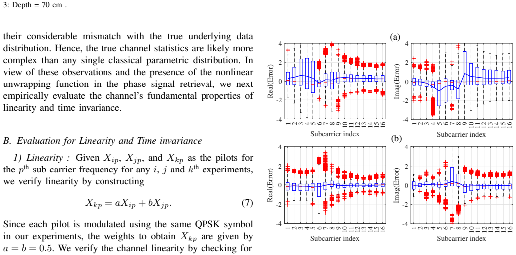
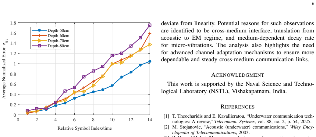
Empirical TARF amplitude data do not align with any single classical parametric distribution; residual-error tests further show that the end-to-end channel deviates from linearity and is time-varying, driven by wavefront-surface interactions, phase unwrapping, and finite surface-wave settling times.
Load-bearing premise
That the observed residual bias, variance, and growth of pilot error with time are caused by intrinsic channel non-linearity and surface dynamics rather than by radar noise, imperfect unwrapping, pool multipath, or insufficient settling between symbols.
Editorial extensions
If this is right
- Classical Rayleigh/Rician equalizers and capacity formulas cannot be used off-the-shelf for TARF links.
- Channel estimation and adaptation must track surface-wave memory that persists across successive OFDM symbols.
- Speaker depth and surface viscosity become first-order design parameters that control both fading statistics and coherence time.
- Reliable TARF systems will need non-linear or data-driven receivers that jointly handle phase unwrapping and surface dynamics.
Reading between the lines
- The same surface-wave memory that breaks time-invariance may also create inter-symbol interference floors that scale with message length, limiting practical packet sizes.
- Because the mismatch with classical models grows with depth, shallow-water TARF may still be approximable by Nakagami-m while deep deployments will require entirely new statistical families.
- Phase-unwrapping artifacts identified as a non-linearity source suggest that alternative micro-motion estimators (e.g., I/Q amplitude tracking) could restore approximate linearity.
Signed reviews
Editorial analysis
A structured set of objections, weighed in public.
Referee Report
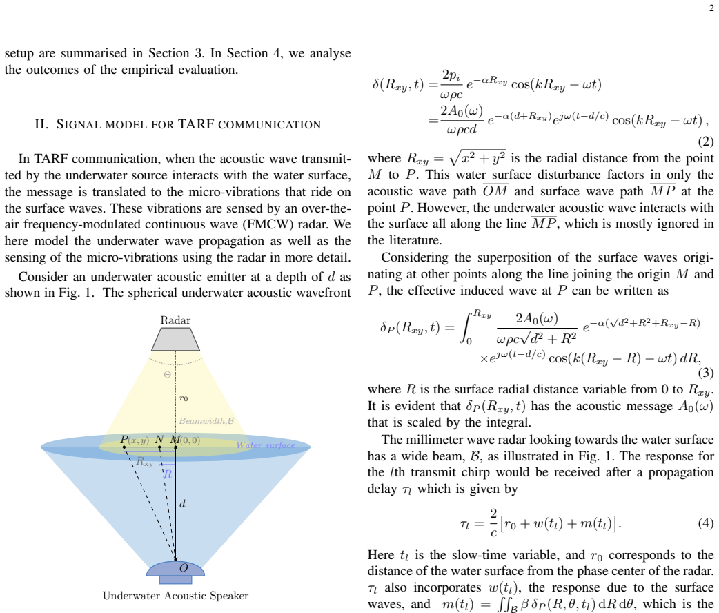
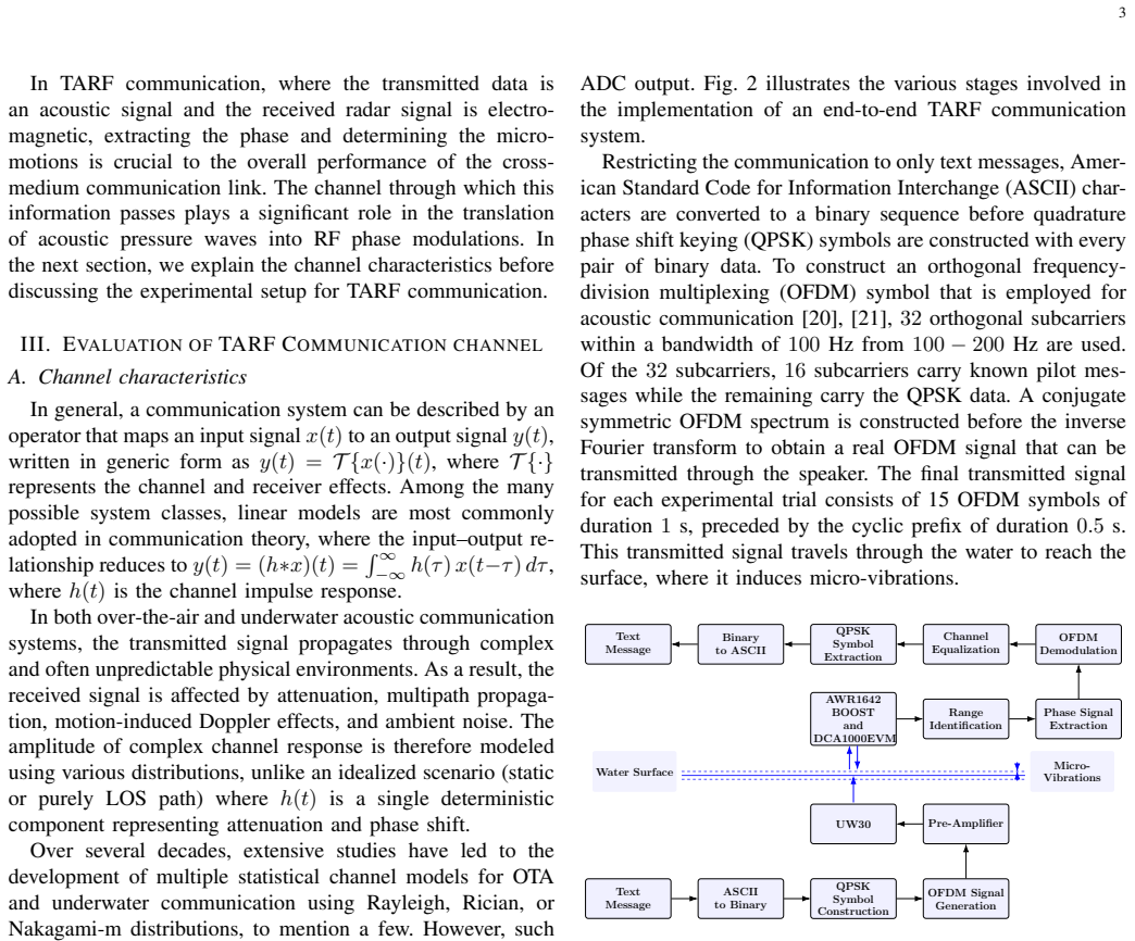
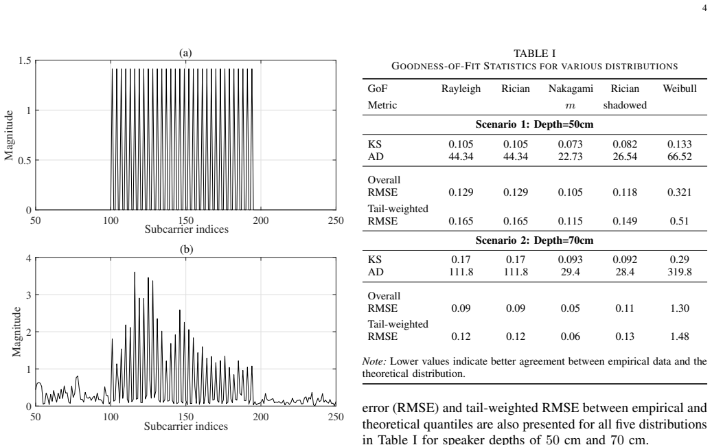
Summary. The manuscript refines the TARF signal model to include superposition of surface waves generated by an underwater acoustic wavefront interacting at multiple points (Eqs. 1–3), then reports an empirical characterization of the end-to-end cross-medium channel. Using pool experiments with OFDM acoustic transmissions (32 subcarriers, 100–200 Hz) sensed by an FMCW radar, the authors apply Kolmogorov–Smirnov, Anderson–Darling, RMSE and P–P analyses (Table I, Fig. 4) against Rayleigh, Rician, Nakagami-m, Weibull and Rician-shadowed distributions. They further test linearity via pilot residual e_lin (Eq. 9, Fig. 5) and time-invariance via normalized pilot deviation e_tiv (Eq. 10, Fig. 6). The central claims are that the empirical amplitude statistics do not match any single classical parametric model (Nakagami-m closest yet still mismatched) and that residual statistics indicate deviation from linearity and time-invariance, attributed to the air–water interface, phase unwrapping and surface dynamics.
Significance. If the empirical mismatch and residual-based conclusions hold under tighter controls, the work supplies the first systematic statistical characterization of the TARF cross-medium channel and a concrete signal-model refinement that accounts for multi-point wavefront–surface interaction. That would be useful for system designers who currently rely on OTA or underwater models alone, and it correctly flags the need for adaptive equalization and settling-time considerations. The experimental pipeline (OFDM pilots, radar phase extraction, multi-depth sweeps) is reproducible in principle and the GoF methodology is standard. The contribution is incremental rather than foundational: it is an empirical observation paper whose strongest claims rest on residual statistics whose causal attribution remains open.
major comments (3)
- Section IV-B, Eqs. (9)–(10) and Figs. 5–6: the central claim that the TARF channel itself “deviates from linearity” and is “time-varying” is drawn from residual statistics computed after the nonlinear unwrap(arg(z(tl))) step of Eq. (6). Because unwrap is discontinuous and path-dependent, residual radar phase noise, multipath inside the finite pool, or incomplete surface-wave settling can produce exactly the observed non-zero bias, subcarrier-dependent variance and growth of e_tiv with symbol index—even if the underlying acoustic-to-surface mapping is linear. The authors themselves list unwrap as a contributing factor yet still attribute the residuals primarily to intrinsic channel non-linearity and surface dynamics. Without a control that bypasses unwrap (e.g., complex baseband amplitude before unwrapping, or a synthetic linear phase reference) or that quantifies the unwrap contribution,
- Section III-B / IV: sample sizes, number of independent trials and confidence intervals on the GoF statistics (Table I) and residual distributions (Figs. 5–6) are never stated. KS, AD and RMSE values are reported to three digits without error bars; box-plot means and variances likewise lack any indication of how many OFDM symbols or independent pool runs underlie them. Without these quantities it is impossible to judge whether the reported mismatches and residual trends are statistically significant or merely consistent with measurement noise.
- Section II, Eq. (3): the refined multi-point surface-wave integral is presented as a modeling contribution, yet it is never used to generate synthetic amplitude statistics that could be compared with the empirical GoF results of Section IV-A. Consequently the refined model remains decorative; the paper’s statistical conclusions rest solely on classical distributions that the authors themselves conclude are inadequate. Either the integral should be evaluated numerically and tested against the same data, or its inclusion should be justified more carefully.
minor comments (5)
- Fig. 3 caption and surrounding text: the transmitted and received OFDM spectra are shown only for a single unspecified depth; stating the depth and the number of averaged symbols would improve reproducibility.
- Eq. (1) and following: the absorption coefficient α and sound speed c are introduced without numerical values or temperature/salinity conditions of the pool; these parameters affect the predicted surface amplitude and should be reported.
- Section III-B: the radar beamwidth B and the precise range-bin selection procedure are mentioned but never quantified; both affect how much surface area contributes to m(tl).
- Typographical inconsistencies: “V . V . Reddy”, “Electro-V oice”, “arXiv:2606.25708v1” date, and occasional missing spaces around equation references should be cleaned.
- References [24]–[26] on viscous damping are cited to support settling-time arguments, yet no measured decay time constant is extracted from the experimental data; a short quantitative comparison would strengthen the discussion.
Circularity Check
No circular derivation: empirical GoF and residual tests are independent of the refined signal model and of any fitted parameters later re-used as predictions.
full rationale
The paper's central claims are purely observational. Section II refines the surface-wave integral (Eq. 3) to include multi-point wavefront interactions, but that expression is never used to generate synthetic data, to constrain the GoF tests of Section IV-A, or to force the residual statistics of Section IV-B. The GoF comparison (Table I, Fig. 4) simply measures empirical CDFs of received pilot amplitudes against five classical external distributions; no parameters of those distributions are fitted on a training subset and then re-presented as predictions. Linearity and time-invariance checks (Eqs. 9-10, Figs. 5-6) compare transmitted pilots with received pilots after the same unwrap step that is part of the measurement chain; the residuals are reported as empirical facts, not derived from a prior model of the channel. There is no self-citation that supplies a uniqueness theorem or an ansatz that later becomes the paper's result. Consequently the derivation chain contains no self-definitional loop, no fitted-input-called-prediction, and no load-bearing self-citation. Score 0 is the correct, proportionate finding.
Assumptions & free parameters
free parameters (3)
- speaker depths (50-80 cm)
- OFDM parameters (32 subcarriers, 100-200 Hz, 15 symbols, 0.5 s CP)
- radar height (~0.5 m) and beamwidth B
assumptions (5)
- domain assumption Classical fading distributions (Rayleigh, Rician, Nakagami-m, Weibull, Rician-shadowed) are the appropriate reference set for amplitude GoF tests
- domain assumption Phase unwrapping of the slow-time radar signal recovers a quantity proportional to surface micro-vibration displacement
- ad hoc to paper Residual e_lin = Y_kp - (a Y_ip + b Y_jp) isolates channel non-linearity rather than additive noise or unwrapping error
- domain assumption Surface-wave settling time and viscosity dominate the observed growth of e_tiv with symbol index
- domain assumption Spherical acoustic spreading plus exponential absorption (Eq. 1) and the integral superposition (Eq. 3) correctly describe the induced surface displacement
Cite this review
Pith. "Pith review of Empirical characterization of the Translational acoustic-RF communication channel." pith.science (2026). https://pith.science/paper/VMU5MI7T
@misc{pith2026260625708,
  author       = {Pith},
  title        = {Pith review of: Empirical characterization of the Translational acoustic-RF communication channel},
  year         = {2026},
  howpublished = {\url{https://pith.science/paper/VMU5MI7T}},
  note         = {Machine review of arXiv:2606.25708}
}
read the original abstract
Translational acoustic-radio frequency (TARF) communication paves the way for translating information from an underwater acoustic signal to the over-the-air (OTA) electromagnetic receiver through the medium interface. The study and characterization of the channel is essential for establishing a reliable communication link. Although channel modeling has been extensively studied for OTA and underwater channels, the amplitude characteristics of the TARF cross-medium channel have not been investigated in comparison with well-known distributions to date. In this work, we define the signal model incorporating the effects of the wavefront-water surface interactions. With the help of numerical and graphical methods, we then attempt to characterize the cross-medium channel with empirical data using existing models developed for OTA and underwater channels. We further evaluate channel linearity and time invariance empirically. Observations from these studies over multiple experiments are detailed with additional discussions that enable better channel characterization to develop reliable and consistent cross-medium TARF communication in challenging scenarios.
Figures
Figures from the paper (3 more)
Reference graph
Works this paper leans on
-
[1]
Underwater communication tech- nologies: A review,
T. Theocharidis and E. Kavallieratou, “Underwater communication tech- nologies: A review,”Telecommn. Systems, vol. 88, no. 2, p. 54, 2025
2025
-
[2]
Acoustic (underwater) communications,
M. Stojanovic, “Acoustic (underwater) communications,”Wiley Ency- clopedia of Telecommunications, 2003
2003
-
[3]
A review on electromagnetic, acoustic, and emerging technologies for submarine communication,
Z. Qu and M. Lai, “A review on electromagnetic, acoustic, and emerging technologies for submarine communication,”IEEE Access, vol. 12, pp. 12 110–12 125, 2024
2024
-
[4]
Recent progress of air/water cross-boundary communications for underwater sensor networks,
H. Luo, J. Wang, F. Bu, R. Ruby, K. Wu, and Z. Guo, “Recent progress of air/water cross-boundary communications for underwater sensor networks,”IEEE Sensors Jnl., vol. 22, no. 9, pp. 8360–8382, 2022
2022
-
[5]
Preliminary investigation of air-to-water visible light communication under strong ambient light,
N. Huang, C. Gong, C. Fu, T. Wei, and Z. Xu, “Preliminary investigation of air-to-water visible light communication under strong ambient light,” inProc. IEEE VTC-Fall, pp. 1–5, 2021
2021
-
[6]
An overview of visible light communication systems,
T. Cevik and S. Yilmaz, “An overview of visible light communication systems,”arXiv preprint, 2015
2015
-
[7]
Air–water communication and sensing with light,
C. J. Carver, Z. Tian, Q. Shao, H. Zhang, K. M. Odame, A. Q. Li, and X. Zhou, “Air–water communication and sensing with light,” inProc. COMSNETS, pp. 371–374, 2022
2022
-
[8]
Networking across boundaries: Enabling wireless communication through the water–air interface,
F. Tonolini and F. Adib, “Networking across boundaries: Enabling wireless communication through the water–air interface,” inProc. ACM SIGCOMM, pp. 117–131, 2018
2018
Show all 26 references
-
[9]
SURF: Eavesdropping on underwater communications from the air,
P. Mollahosseini, S. S. Afzal, F. Adib, and Y . Ghasempour, “SURF: Eavesdropping on underwater communications from the air,” inProc. ACM MobiCom, pp. 815–829, 2024
2024
-
[10]
Cross-medium communication combining acoustic wave and millimeter wave,
F. Qu, J. Qian, J. Wang, X. Lu, M. Zhang, X. Bai, Z. Ran, X. Tu, Z. Liu, and Y . Wei, “Cross-medium communication combining acoustic wave and millimeter wave,”IEEE Journal of Oceanic Engineering, vol. 47, no. 2, pp. 483–492, 2021
2021
-
[11]
Snooping underwater communications via low-cost mmwave radars,
P. Mollahosseini, S. S. Afzal, F. Adib, and Y . Ghasempour, “Snooping underwater communications via low-cost mmwave radars,” inProc. ACM MobiCom, pp. 1638–1640, 2024
2024
-
[12]
T. S. Rappaport,Wireless Communications: Principles and Practice. Prentice Hall, 2002
2002
-
[13]
Goldsmith,Wireless Communications
A. Goldsmith,Wireless Communications. Cambridge Univ. Press, 2005
2005
-
[14]
J. G. Proakis,Digital Communications. McGraw-Hill, 2001
2001
-
[15]
J. G. Proakis and M. Salehi,Communication Systems Engineering. Prentice Hall, 2001
2001
-
[16]
Underwater acoustic communication channels: Propagation models and statistical characterisation,
M. Stojanovic and J. Preisig, “Underwater acoustic communication channels: Propagation models and statistical characterisation,”IEEE Communications Magazine, vol. 47, no. 1, pp. 84–89, 2009
2009
-
[17]
Ricean shadowed statistical characterization of shallow water acoustic channels for wireless communications,
F. Ruiz-Vega, M. C. Clemente, P. Otero, and J. F. Paris, “Ricean shadowed statistical characterization of shallow water acoustic channels for wireless communications,” https://arxiv.org/abs/1112.4410,. 2011
2011 arXiv
-
[18]
Channel modeling for underwater acoustic network simulation,
W. Pu, “Channel modeling for underwater acoustic network simulation,” Journal of Networks, vol. 5, no. 1, pp. 1–10, 2010
2010
-
[19]
Lurton,An Introduction to Underwater Acoustics: Principles and Applications
X. Lurton,An Introduction to Underwater Acoustics: Principles and Applications. Springer, 2002
2002
-
[20]
J. G. Proakis and M. Salehi,Digital Communications. McGraw-Hill, 2008
2008
-
[21]
Zhou and Z
S. Zhou and Z. Wang,OFDM for Underwater Acoustic Communica- tions. Wiley, 2014
2014
-
[22]
R. B. D’Agostino,Goodness-of-Fit Techniques. CRC Press, 2017
2017
-
[23]
Statis- tical studies using goodness-of-fit techniques with dynamic underwater visible light communication channel modeling,
M. Mahmoud, A. I. Boghdady, A. A. El-Fikky, and M. H. Aly, “Statis- tical studies using goodness-of-fit techniques with dynamic underwater visible light communication channel modeling,”IEEE Access, vol. 9, pp. 57 716–57 725, 2021
2021
-
[24]
Damping for fractional wave equations and applications to water waves,
T. Alazard, J. L. Marzuola, and J. Wang, “Damping for fractional wave equations and applications to water waves,” https://arxiv.org/abs/2308.09288,. 2023. 7
2023 arXiv
-
[25]
Viscous damping of gravity-capillary waves: Dispersion relations and nonlinear corrections,
A. Armaroli, D. Eeltink, M. Brunetti, and J. Kasparian, “Viscous damping of gravity-capillary waves: Dispersion relations and nonlinear corrections,”Phys. Rev. Fluids, vol. 3, no. 12, p. 124803, 2018
2018
-
[26]
Time-dependent nonlinear gravity–capillary surface waves with viscous dissipation and wind forc- ing,
J. Shelton, P. Milewski, and P. H. Trinh, “Time-dependent nonlinear gravity–capillary surface waves with viscous dissipation and wind forc- ing,”J. Fluid Mech., vol. 1003, p. A13, 2025
2025
Reviewed July 12, 2026 · model on record in the stance chip above.
Discussion (0). Continue with ORCID to comment.