REVIEW 3 major objections 5 minor 9 references
An auto-scaling wide dynamic range current to frequency converter for real-time monitoring of signals in neuromorphic systems
T0 review · 3 major / 5 minor · reviewed 2026-08-14 · deepseek-v4-flash
Pith's one-line read A compact auto-scaling converter turns picoampere-to-microampere neural currents into asynchronous spike trains with a six-decade dynamic range, letting neuromorphic chips stream their internal analog signals.
desk verdict A real auto-ranging current-to-frequency converter for neuromorphic current monitoring, linear over about five decades, but the 6-decade/pA claim needs external calibration and the β/α arithmetic is wrong. read the letter →
The pith
A machine-rendered reading of the paper's core claim, the machinery that carries it, and where it could break.
The reading
What carries the argument
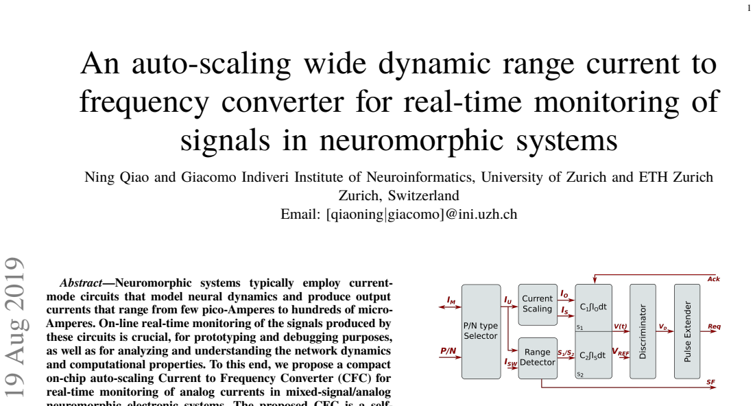
The central object is the range-detecting current-mirror network followed by a dual-capacitor integrator. The P/N selector rectifies the input current $I_M$ to $I_U$; transistors M6–M8 copy $I_U$ to $I_O$, and M6–M10 copy it to $I_S = \beta I_O$ with $\beta = 10$. A comparator on the gate of M6 decides whether $I_M$ is below or above a programmable threshold, generating signals S1 and S2 that route either $I_O$ onto $C_1$ or $I_S$ onto $C_2$, where $C_2/C_1 = \alpha = 10$. The discriminator fires an asynchronous AER request pulse when the integrating capacitor voltage crosses the low reference voltage, and the acknowledge signal resets the integrator. Equation (1) is the governing identity: it ties the inter-spike interval directly to the monitored current, with the auto-scaling factor $\alpha/\beta$ determining which input range maps to a given output rate.
What would settle it
Inject calibrated currents below 10 pA, for example 3 pA and 5 pA, from a precision source into the converter input and count output pulses over a fixed window; the governing equation predicts a specific nonzero rate, and observing no pulses or a rate that deviates from the predicted linear relation would falsify the claimed low-current sensitivity. A second check is to compare the converter-derived current against a calibrated ammeter near the auto-scaling threshold and verify the pulse-rate continuity across the switch.
Extended reading notes
Core claim
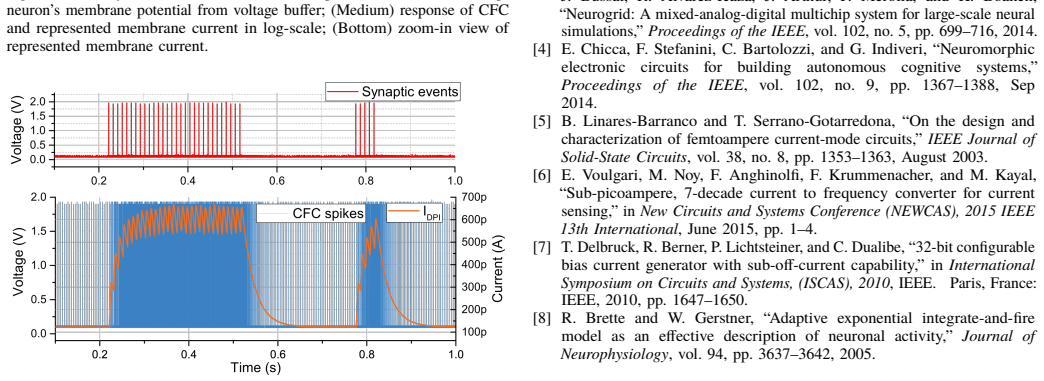
The central discovery is an asynchronous auto-scaling current-to-frequency converter whose inter-spike interval obeys $\delta T = \beta C(V_{\mathrm{refH}} - V_{\mathrm{refL}})/(\alpha I_{\mathrm{mon}})$, so that the output pulse rate is linearly proportional to the monitored current $I_{\mathrm{mon}}$. A range detector compares the rectified input current to a threshold and selects whether to integrate the un-scaled current $I_O$ on a small capacitor $C_1$ or the scaled current $I_S = \beta I_O$ with $\beta = 10$ on a larger capacitor $C_2 = 10 C_1$, giving a total 100-fold scaling for large currents. In measurements, the circuit accurately measures currents from about 10 pA to 1 µA; currents below about 5.5 pA produce no output because of current-mirror leakage, and currents above 1 µA distort because the reset pulse becomes comparable to the inter-spike interval. Connected to an adaptive exponential integrate-and-fire neuron and a DPI synapse, the converter output reproduces the exponential decay and rise of the log-domain membrane current, demonstrating that the converted pulse train is a faithful real-time monitor of neural dynamics.
Load-bearing premise
The load-bearing premise is that the current mirrors copy the small input current to the integration branch with negligible leakage and mismatch down to picoampere levels; below about 5.5 pA this copying itself is the reason the output goes silent, so if mirror accuracy degrades, the linear mapping fails exactly where the claimed sensitivity matters most.
Editorial extensions
If this is right
- Neuromorphic chips can monitor their internal log-domain currents on-line during experiments, without the compression artifacts introduced by voltage buffering.
- Neuron and synapse parameters such as time constants and synaptic weights become directly readable from the inter-spike intervals of the converter's pulse train.
- Because the output rate is kept within a limited range while the input spans six decades, the same circuit can serve both slow adaptive neural dynamics and fast transient currents without reconfiguration.
- With a worst-case power dissipation of about 36 nW at a 100 kHz output rate, embedding one converter per monitored node in a large-scale neuromorphic system becomes practical.
- The programmable threshold and bias voltages let designers tune the same design for different current ranges and output rates across applications.
Reading between the lines
- I infer that the 5.5 pA floor is a leakage limit of the 180 nm mirror network, not a fundamental barrier, so techniques used in femtoampere current-mode circuits could push the operational floor lower in a derivative design.
- A testable extension is to drive the converter with a sinusoidally modulated current and measure the recovered amplitude and phase across the auto-scaling threshold; this would quantify where the finite reset pulse limits bandwidth at the high-current end.
- The range-detection state signals S1 and S2 could be read out as an explicit scale bit, effectively doubling the bit depth of the current readout for a given output rate.
- The same auto-scaling principle could be applied to other sensor front-ends that need wide dynamic range with limited output bandwidth, such as photodiode or electrochemical current monitors.
Signed reviews
Editorial analysis
A structured set of objections, weighed in public.
Referee Report
Summary. The paper presents a compact asynchronous current-to-frequency converter (CFC) for real-time monitoring of analog currents in neuromorphic systems. The circuit auto-detects the scale of the input current and switches between two integration paths, producing pulse-frequency-modulated output spikes whose rate is claimed to be linearly proportional to the input current. The authors derive the inter-spike interval in Eq. (1), describe the block-level and transistor-level implementation, and report measurements from six instances fabricated in a 180 nm CMOS process. Experimental results show linear conversion over a range stated as approximately 10 pA to 1 µA, with evidence of leakage below 5.5 pA and distortion above 1 µA. The paper also demonstrates real-time monitoring of silicon neuron and synapse currents. The central claim, repeated in the abstract and conclusions, is a dynamic input range of "up to 6 decades, ranging from pico-Amps to micro-Amps".
Significance. If the headline range were fully supported, this CFC would be a valuable, compact monitoring block for mixed-signal neuromorphic systems. The paper has genuine strengths: Eq. (1) is a clean standard capacitor-integration derivation; Fig. 4 shows broadly linear conversion over about five decades; the circuit is compact (150 µm × 40 µm) and low-power (about 36 nW at the maximum foreseen rate); and the neuron/synapse recordings demonstrate practical utility for real-time monitoring. However, the measured data support only about five decades (10 pA to 1 µA), not the claimed six decades from picoamperes to microamperes, and the validation at the picoampere end relies on current inferred from the CFC itself and a SPICE simulation rather than a calibrated external current source. These issues are load-bearing for the paper's central quantitative claim and need to be addressed.
major comments (3)
- [Abstract, Section III (Fig. 4), Conclusions] The claim of "up to 6 decades, ranging from pico-Amps to micro-Amps" is contradicted by the reported data. Section III states that the circuit "can accurately measure currents ranging from approximately 10pA to 1 µA", that "currents smaller than 5.5pA produce no effective output, mainly because of leakage issues in the current mirrors", and that "currents larger than 1µA lead to distortions". A range from 10 pA to 1 µA is five decades, and even the more optimistic 5.5 pA to 1 µA is about 5.3 decades. The 6-decade claim should be removed or replaced with an explicit statement that the demonstrated range is about five decades.
- [Section II, Eq. (1)] The definitions of β and α are internally inconsistent. The text first says "IS = βIO, with β<1", then later says "we set the current mirror ratio β=M10/M9 to 10, and the integration capacitor ratio α=C2/C1 to 10. So for currents larger than ... the total scaling factor is β/α=100". If β=10 and α=10, then β/α equals 1, not 100, and β=10 also contradicts the earlier β<1. Please correct the notation, the arithmetic, and the formula for the total scaling factor, because Eq. (1) is the central quantitative relation of the paper.
- [Section III, Fig. 5] The picoampere-end validation is not independent. The "corresponding measured current" is computed from the CFC output itself using the converter's transfer relation, and the external reference is a SPICE simulation of the same p-FET bias transistor, not a calibrated ammeter or a calibrated current source. Since the paper also reports that currents below 5.5 pA produce no output, the claim of pA-range sensitivity should be softened to "tens of picoamperes" unless a measurement with a calibrated sub-pA current source is provided.
minor comments (5)
- [Section II, Pulse Extender discussion] The text states "reset pulse lengths of TRST = 0.1µm are sufficiently smaller than the typical δTs produced"; the unit is almost certainly microseconds (µs), not micrometers (µm).
- [Section I] There is a typo: "subtreshold" should be "subthreshold".
- [Fig. 4 caption] The caption lists five current sweeps and the figure shows the data; consider marking the region below 10 pA where no effective output is produced, so that the figure does not misleadingly suggest a full six-decade span.
- [Section II, Fig. 2] The notation is inconsistent in small ways: "Vref H" and "Vref L" appear with irregular spacing, and phrases like "the current throughM13" are missing spaces. A careful formatting pass would improve readability.
- [Section III] The sentence "currents larger than 1µA lead to distortions, because of ... the finite pulse width of the spikes TRST" should clarify whether this upper limit depends on the chosen bias settings (e.g., the 100 nA scaling threshold) or is a fixed property of the implementation.
Circularity Check
No circularity: Eq. (1) follows from capacitor integration physics, and the experimental validation compares CFC-derived currents to an independent SPICE simulation of the bias transistor.
full rationale
The paper's central derivation is self-contained. Eq. (1), δT = βC(VrefH − VrefL)/(αImon), is obtained directly from the circuit topology: the selected mirror ratio β, the selected capacitor ratio α, the programmed reference-voltage swing, and the capacitance determine the integration slope, so the inter-spike interval is the ratio of a fixed charge to the input current. No free parameter is fitted to the measured pulse rates and then reused to 'predict' those same rates. The experimental section converts measured pulse intervals back to currents using the same known component values, which is the normal operating principle of a current-to-frequency converter, not a circular validation. The p-FET injection current is independently checked against a SPICE simulation of the same transistor, and the observed 5.5 pA leakage floor is reported as an empirical limitation. This floor, together with the stated 10 pA to 1 µA measured range, weakens the literal '6 decades from pico-Amps to micro-Amps' claim, but that is an accuracy/overstatement issue, not circular reasoning. Self-citations are contextual: Ref. [4] supplies the neuron/synapse circuits being monitored, Ref. [7] supplies the bias generator, and Ref. [8] supplies the AdExp model; none of these is used as an unverified premise to force the converter's transfer function. The derivation does not reduce to its inputs by construction.
Assumptions & free parameters
free parameters (5)
- β (current scaling ratio IS/IO) =
stated both as β<1 and as β=M10/M9=10; text is inconsistent
- α (capacitor ratio C2/C1) =
10
- C1 and C2 (integration capacitors) =
C1=100 fF, C2=1 pF
- VrefH - VrefL (integrator voltage swing) =
example 1 V
- ISW (scaling reference threshold) =
10 nA in example; 100 nA in Fig. 5 experiment
assumptions (4)
- domain assumption Current mirror copies are exact: IS = β·IO and IO ≈ IM after rectification, with negligible leakage and mismatch.
- domain assumption The reset pulse duration is negligible compared to the inter-spike interval.
- domain assumption The SPICE simulation with the foundry transistor model accurately represents the fabricated transistor's current.
- standard math Capacitor integration follows Q=CV and I=C dV/dt over the operating range.
Cite this review
Pith. "Pith review of An auto-scaling wide dynamic range current to frequency converter for real-time monitoring of signals in neuromorphic systems." pith.science (2026). https://pith.science/paper/WVQJZ4K2
@misc{pith2026190806545,
  author       = {Pith},
  title        = {Pith review of: An auto-scaling wide dynamic range current to frequency converter for real-time monitoring of signals in neuromorphic systems},
  year         = {2026},
  howpublished = {\url{https://pith.science/paper/WVQJZ4K2}},
  note         = {Machine review of arXiv:1908.06545}
}
read the original abstract
Neuromorphic systems typically employ current-mode circuits that model neural dynamics and produce output currents that range from few pico-Amperes to hundreds of micro-Amperes. On-line real-time monitoring of the signals produced by these circuits is crucial, for prototyping and debugging purposes, as well as for analyzing and understanding the network dynamics and computational properties. To this end, we propose a compact on-chip auto-scaling Current to Frequency Converter (CFC) for real-time monitoring of analog currents in mixed-signal/analog neuromorphic electronic systems. The proposed CFC is a self-timed asynchronous circuit that has a wide dynamic input range of up to 6 decades, ranging from pico-Amps to micro-Amps, with high current measurement sensitivity. To produce a linear output frequency response, while properly covering the wide dynamic input range, the circuit automatically detects the scale of the input current and adjusts the scale of its output firing rate accordingly. Here we describe the proposed circuit and present experimental results measured from multiple instances of the circuit, implemented using a standard 180 nm CMOS process, and interfaced to silicon neuron and synapse circuits for real-time current monitoring. We demonstrate how the circuit is suitable for measuring neural dynamics by showing the converted response properties of the chip silicon neurons and synapses as they are stimulated by input spikes.
Figures


Figures from the paper (3 more)


Reference graph
Works this paper leans on
-
[5]
B. Linares-Barranco and T. Serrano-Gotarredona, ``On the design and characterization of femtoampere current-mode circuits,'' IEEE Journal of Solid-State Circuits , vol. 38, no. 8, pp. 1353--1363, August 2003
work page 2003
-
[6]
E. Voulgari, M. Noy, F. Anghinolfi, F. Krummenacher, and M. Kayal, ``Sub-picoampere, 7-decade current to frequency converter for current sensing,'' in New Circuits and Systems Conference (NEWCAS), 2015 IEEE 13th International, June 2015, pp. 1--4
work page 2015
-
[1]
Mead, ``Neuromorphic electronic systems,'' Proceedings of the IEEE , vol
C. Mead, ``Neuromorphic electronic systems,'' Proceedings of the IEEE , vol. 78, no. 10, pp. 1629--36, 1990
work page 1990
-
[2]
K. Boahen, ``Point-to-point connectivity between neuromorphic chips using address-events,'' IEEE Transactions on Circuits and Systems II , vol. 47, no. 5, pp. 416--34, 2000
work page 2000
-
[3]
B. V. Benjamin, P. Gao, E. McQuinn, S. Choudhary, A. R. Chandrasekaran, J. Bussat, R. Alvarez-Icaza, J. Arthur, P. Merolla, and K. Boahen, ``Neurogrid: A mixed-analog-digital multichip system for large-scale neural simulations,'' Proceedings of the IEEE , vol. 102, no. 5, pp. 699--716, 2014
work page 2014
- [4]
-
[7]
T. Delbruck, R. Berner, P. Lichtsteiner, and C. Dualibe, ``32-bit configurable bias current generator with sub-off-current capability,'' in International Symposium on Circuits and Systems, ( ISCAS ), 2010 , IEEE. 1em plus 0.5em minus 0.4em Paris, France: IEEE, 2010, pp. 1647--1650
work page 2010
-
[8]
R. Brette and W. Gerstner, ``Adaptive exponential integrate-and-fire model as an effective description of neuronal activity,'' Journal of Neurophysiology, vol. 94, pp. 3637--3642, 2005
work page 2005
Show all 9 references
-
[9]
y qpr pa ny(W8Y L 'gw /eXqD h X ;wo:/ߦ 7ჷ\0f:3m O c
11em plus .33em minus .07em 4000 4000 100 4000 4000 500 `\.=1000 = #1 \@IEEEnotcompsoconly \@IEEEcompsoconly #1 * [1] 0pt [0pt][0pt] #1 * [1] 0pt [0pt][0pt] #1 * \| ** #1 \@IEEEauthorblockNstyle \@IEEEcompsocnotconfonly \@IEEEauthorblockAstyle \@IEEEcompsocnotconfonly \@IEEEco...
Reviewed August 14, 2026 · model on record in the stance chip above.
Discussion (0). Continue with ORCID to comment.