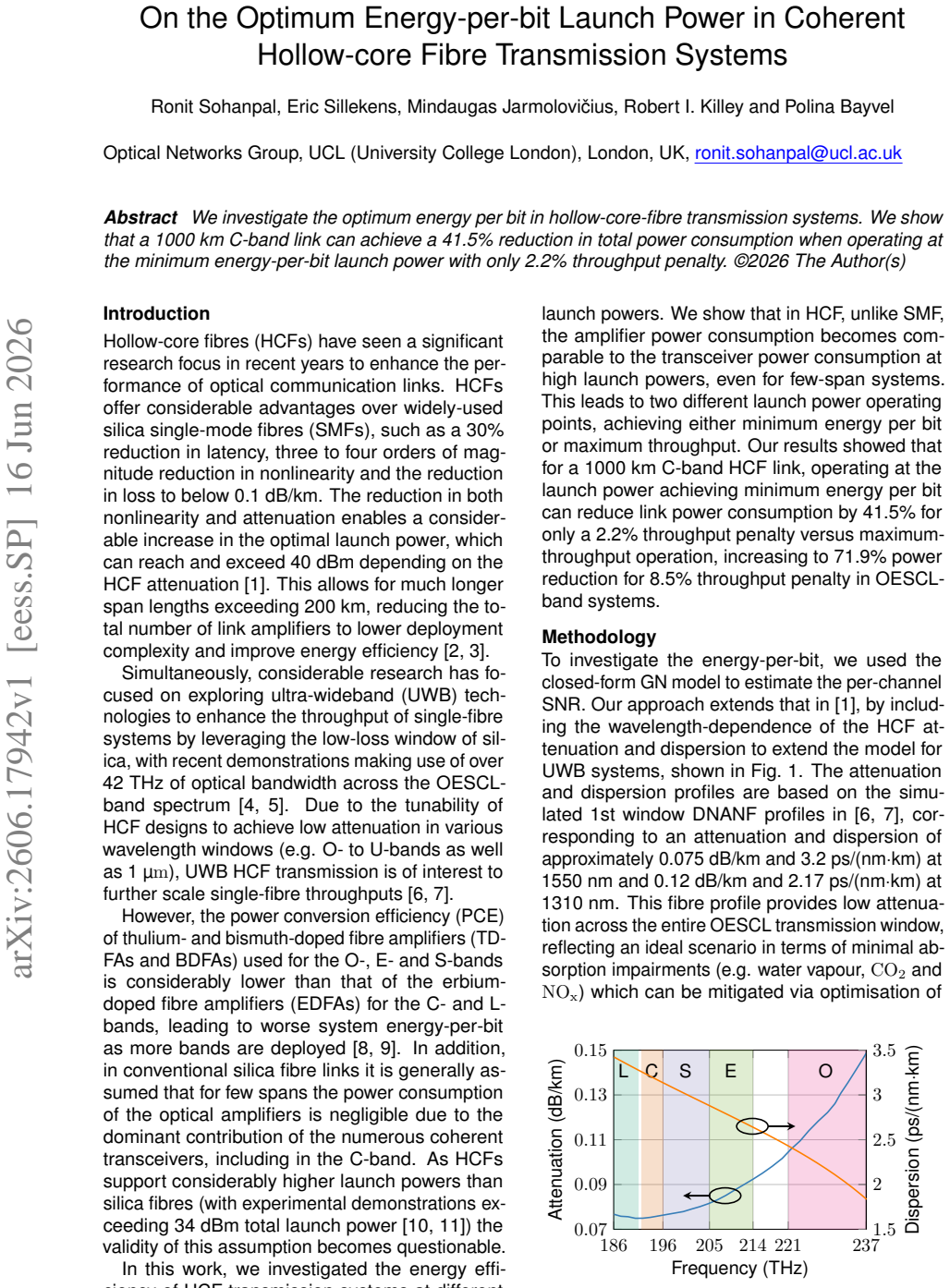
On the Optimum Energy-per-bit Launch Power in Coherent Hollow-core Fibre Transmission Systems
Pith reviewed 2026-06-26 22:51 UTC · model grok-4.3
The pith
A 1000 km C-band hollow-core fibre link reduces total power consumption by 41.5% at the minimum energy-per-bit launch power, with a 2.2% throughput penalty.
A machine-rendered reading of the paper's core claim, the machinery that carries it, and where it could break.
Core claim
In hollow-core fibre systems the energy per bit is minimized at a launch power where the increase in signal strength is balanced against the growth of nonlinear penalties. Operating a 1000 km C-band link at this point produces a 41.5% reduction in total power consumption accompanied by only a 2.2% reduction in throughput.
What carries the argument
The energy-per-bit quantity obtained from the link power-consumption model that includes launch power, amplifier consumption, and nonlinear penalties specific to hollow-core fibre.
If this is right
- Total power consumption falls by 41.5% while throughput falls by only 2.2%.
- The same minimum-energy-per-bit operating point applies to C-band coherent links over hollow-core fibre.
- Nonlinear penalties set the location of the energy-per-bit minimum rather than linear loss alone.
- Power savings scale with distance because the nonlinear contribution grows with length.
Where Pith is reading between the lines
- Operators could reduce electricity cost and heat load by deliberately detuning launch power away from the usual maximum-capacity point.
- The result may shift the economic case for replacing standard fibre with hollow-core spans in power-sensitive routes.
- Further gains are possible if the same energy-per-bit minimization is combined with adaptive modulation or sleep-mode amplifiers.
Load-bearing premise
The link model used to compute energy-per-bit and throughput accurately captures all relevant power-consuming components and nonlinear penalties for hollow-core fibre at the stated distances and wavelengths.
What would settle it
Direct measurement of total electrical power draw and net throughput on a real 1000 km hollow-core fibre span when the launch power is set to the calculated minimum-energy-per-bit value.
Figures
read the original abstract
We investigate the optimum energy per bit in hollow-core-fibre transmission systems. We show that a 1000 km C-band link can achieve a 41.5% reduction in total power consumption when operating at the minimum energy-per-bit launch power with only 2.2% throughput penalty.
Editorial analysis
A structured set of objections, weighed in public.
Referee Report
Summary. The manuscript investigates the optimum energy-per-bit launch power in coherent hollow-core fibre (HC-PCF) transmission systems. It claims that a 1000 km C-band link achieves a 41.5% reduction in total power consumption when operated at the minimum energy-per-bit launch power, incurring only a 2.2% throughput penalty.
Significance. If the underlying power-consumption model and hollow-core-fibre nonlinear interference term are accurate and complete, the result would be significant for energy-efficient long-haul system design, as it identifies a practical operating point that trades minimal rate for substantial power savings in a technology with intrinsically lower nonlinearity.
major comments (2)
- The 41.5% power-reduction and 2.2% throughput-penalty figures are obtained by minimising total electrical power divided by throughput. No explicit model is supplied that enumerates every power-consuming block (transmitter, receiver, DSP, each EDFA stage) or that specifies the nonlinear interference coefficient and loss profile used for HC-PCF; without these, the location of the minimum and the reported percentages cannot be reproduced or stress-tested.
- The abstract states the result for a 1000 km C-band link but provides neither the capacity formula employed to convert SNR to achievable rate nor any validation against measured HC-fibre parameters at the stated wavelengths and distances; this renders the headline numbers unverifiable from the given material.
Simulated Author's Rebuttal
We thank the referee for their comments on our manuscript. We provide point-by-point responses below, agreeing where additional detail is needed for reproducibility and indicating the corresponding revisions.
read point-by-point responses
-
Referee: The 41.5% power-reduction and 2.2% throughput-penalty figures are obtained by minimising total electrical power divided by throughput. No explicit model is supplied that enumerates every power-consuming block (transmitter, receiver, DSP, each EDFA stage) or that specifies the nonlinear interference coefficient and loss profile used for HC-PCF; without these, the location of the minimum and the reported percentages cannot be reproduced or stress-tested.
Authors: We agree that an explicit enumeration of all power-consuming blocks and the precise values of the nonlinear interference coefficient and loss profile for HC-PCF are required for full reproducibility. The revised manuscript will include a complete breakdown of the power model together with the exact coefficient and loss values employed. revision: yes
-
Referee: The abstract states the result for a 1000 km C-band link but provides neither the capacity formula employed to convert SNR to achievable rate nor any validation against measured HC-fibre parameters at the stated wavelengths and distances; this renders the headline numbers unverifiable from the given material.
Authors: The capacity formula is the standard Shannon formula applied to the SNR after nonlinear interference, and the fibre parameters are taken from published HC-PCF measurements. The revised manuscript will state the capacity formula explicitly and cite the specific measured parameters used for the C-band wavelengths and distances considered. revision: yes
Circularity Check
No circularity detected; derivation chain not visible in supplied text
full rationale
The abstract states a 41.5% power reduction at minimum energy-per-bit launch power but supplies no equations, fitting procedures, or self-citations. The reader's summary explicitly notes that no equations or fitting are visible, preventing any inspection for self-definitional, fitted-input, or self-citation circularity. Without load-bearing steps that reduce to inputs by construction, the result cannot be flagged as circular. The model is treated as an external computation whose completeness is a separate modeling question, not a circularity issue.
Axiom & Free-Parameter Ledger
Reference graph
Works this paper leans on
-
[1]
Opportunities and Chal- lenges for Long-Distance Transmission in Hollow-Core Fibres
P . Poggiolini and F . Poletti, “Opportunities and Chal- lenges for Long-Distance Transmission in Hollow-Core Fibres”,Journal of Lightwave Technology, vol. 40, no. 6, pp. 1605–1616, Mar. 2022.DOI: 10.1109/JLT.2021. 3140114
-
[2]
The Potential for Span Length Increase with NANF
P . Poggiolini, G. Bosco, Y . Jiang, and F . Poletti, “The Potential for Span Length Increase with NANF”, in2023 IEEE Photonics Conference (IPC), Nov. 2023, pp. 1–2. DOI:10.1109/IPC57732.2023.10360569
-
[3]
On High-Power Optical Amplification in Hollow Core Fibers for Energy Efficiency and Network Throughput Maximization
G. Sticca, M. Ibrahimi, N. Di Cicco, F . Musumeci, and M. Tornatore, “On High-Power Optical Amplification in Hollow Core Fibers for Energy Efficiency and Network Throughput Maximization”, inECOC 2024; 50th Euro- pean Conference on Optical Communication, Sep. 2024, pp. 1010–1013
2024
-
[4]
J. Y ang, M. Jarmoloviˇcius, Z. Gan, H. Buglia, R. So- hanpal, R. Aparecido, E. Sillekens, R. I. Killey, and P . Bayvel, “Challenges and Breakthroughs in Modeling and Designing Ultrawideband Optical Fibre Communication Systems and Networks”,Journal of Lightwave Tech- nology, vol. 44, no. 3, pp. 944–954, Feb. 2026.DOI: 10.1109/JLT.2025.3640009
-
[5]
450 Tb/s GMI, 42.4 THz, OESCL- Band Transmission Over a Field-Deployed Fiber
R. S. Luis, J. Y ang, R. Aparecido, M. Jarmoloviˇcius, E. Sillekens, R. Sohanpal, Z. Gan, A. Donodin, V. Mikhailov, J. Luo, D. DiGiovanni, N. Fontaine, L. Dallachiesa, M. Mazur, R. Ryf, H. Chen, D. Neilson, I. D. Phillips, W. Forysiak, S. K. Turitsyn, D. Orsuti, H. Furukawa, R. I. Killey, and P . Bayvel, “450 Tb/s GMI, 42.4 THz, OESCL- Band Transmission O...
2026
-
[6]
Broadband optical fibre with an attenuation lower than 0.1 decibel per kilometre
M. Petrovich, E. Numkam Fokoua, Y . Chen, H. Sakr, A. I. Adamu, R. Hassan, D. Wu, R. Fatobene Ando, A. Papadimopoulos, S. R. Sandoghchi, G. Jasion, and F . Poletti, “Broadband optical fibre with an attenuation lower than 0.1 decibel per kilometre”,Nature Photonics, vol. 19, no. 11, pp. 1203–1208, Nov. 2025.DOI: 10 . 1038/s41566-025-01747-5
2025
-
[7]
First Dual-Band Hybrid Window Antiresonant HCF with 0.13 dB/km loss at 1 µm and 0.11 dB/km at 1.55 µm
G. A. Mahdiraji, S. M. A. Mousavi, D. Wu, T. Varghese, N. K. Baddela, K. Wisniowski, S. B. Gorajoobi, A. Shak- iba, M. Rahman, G. Guerra, E. N. Fokoua, Y . Chen, G. Jasion, and F . Poletti, “First Dual-Band Hybrid Window Antiresonant HCF with 0.13 dB/km loss at 1 µm and 0.11 dB/km at 1.55 µm”, inOptical Fiber Communication Conference (OFC), Th4B.8, 2026
2026
-
[8]
CO2 Elim- ination in Hollow-Core Fibre via Post-Processing
R. Sohanpal, J. Y ang, E. Sillekens, H. Buglia, M. Tan, D. Pratiwi, R. I. Killey, and P . Bayvel, “Measurement and Analysis of the Power Consumption of Hybrid-Amplified SCL-Band Links”, in2025 European Conference on Optical Communications (ECOC), Sep. 2025, pp. 1–4. DOI:10.1109/ECOC66593.2025.11263434
-
[9]
Ultra-Wideband Transmission Systems From an En- ergy Perspective: Which Band is Next?
R. Sohanpal, M. Jarmolovi ˇcius, J. Y ang, E. Sillekens, R. Aparecido, V. Mikhailov, J. Luo, D. J. DiGiovanni, R. S. Luis, H. Furukawa, R. I. Killey, and P . Bayvel, “Ultra-Wideband Transmission Systems From an En- ergy Perspective: Which Band is Next?”, inOptical Fiber Communication Conference (OFC), M3C.3, 2026
2026
-
[10]
222-km-long Hybrid Span Transmission Systems made of Support Tube Hollow Core Fiber and of Standard Single Mode Fiber using High Power Doped Fiber Amplifier
H. Mardoyan, R. S. B. Ospina, C. C. Carrero, A. Ghazisaeidi, R. Boddeda, P . Li, L. Zhang, J. Luo, C. Fu, C. Hu, and J. Renaudier, “222-km-long Hybrid Span Transmission Systems made of Support Tube Hollow Core Fiber and of Standard Single Mode Fiber using High Power Doped Fiber Amplifier”,Optical Fiber Com- munication Conference, 2026
2026
-
[11]
Trans- mitter Power Optimization for Uniform Performance Multi- Span Hollow-Core Fiber Transmission
Y . Hong, M. Kamalian-Kopae, A. Ali, B. Gholizadeh, S. Bawn, J. Hooley, S. B. Gorajoobi, C. Wallace, J. Gaudette, D. J. Richardson, and B. J. Puttnam, “Trans- mitter Power Optimization for Uniform Performance Multi- Span Hollow-Core Fiber Transmission”,Optical Fiber Communication Conference, 2026
2026
-
[12]
CO2 Elim- ination in Hollow-Core Fibre via Post-Processing
Y . Xiong, R. Zhao, D. Ge, S. Gao, Y . Sun, D. Wang, D. Zhang, H. Li, W. Ding, and Y . Wang, “CO2 Elim- ination in Hollow-Core Fibre via Post-Processing”, in 2025 European Conference on Optical Communica- tions (ECOC), W.02.01.08, Sep. 2025, pp. 1–4.DOI: 10.1109/ECOC66593.2025.11263127
-
[13]
Leveraging Digital Subcarrier Multiplexing for Long-Haul Transmission over HCFs in the Presence of IMI
R. S. B. Ospina, C. C. Carrero, H. Mardoyan, A. Ghazisaeidi, R. Boddeda, P . Li, L. Zhang, J. Luo, and J. Renaudier, “Leveraging Digital Subcarrier Multiplexing for Long-Haul Transmission over HCFs in the Presence of IMI”,Optical Fiber Communication Conference, 2026, Th1J.3
2026
-
[14]
Repeater Power Conversion Efficiency in Submarine Optical Com- munication Systems
X. Liang, J. D. Downie, and J. E. Hurley, “Repeater Power Conversion Efficiency in Submarine Optical Com- munication Systems”,IEEE Photonics Journal, vol. 13, no. 1, pp. 1–10, Feb. 2021.DOI: 10.1109/JPHOT.2021. 3054624
discussion (0)
Sign in with ORCID, Apple, or X to comment. Anyone can read and Pith papers without signing in.