REVIEW 3 major objections 4 minor 19 references
A Class D Power Amplifier for Multi-Frequency Eddy Current Testing Based on Multi-Simultaneous-Frequency Selective Harmonic Elimination Pulse Width Modulation
T0 review · 3 major / 4 minor · reviewed 2026-08-14 · deepseek-v4-flash
Pith's one-line read This paper shows that a single switch-mode (Class D) power amplifier can generate a multi-simultaneous-frequency coil current for eddy current testing by keeping, rather than eliminating, selected harmonics.
desk verdict Promising hardware demonstration of multi-frequency Class D excitation, but the optimization formulation in Eq. (9) is degenerate and the claimed harmonic control is unsupported as written. read the letter →
The pith
A machine-rendered reading of the paper's core claim, the machinery that carries it, and where it could break.
The reading
What carries the argument
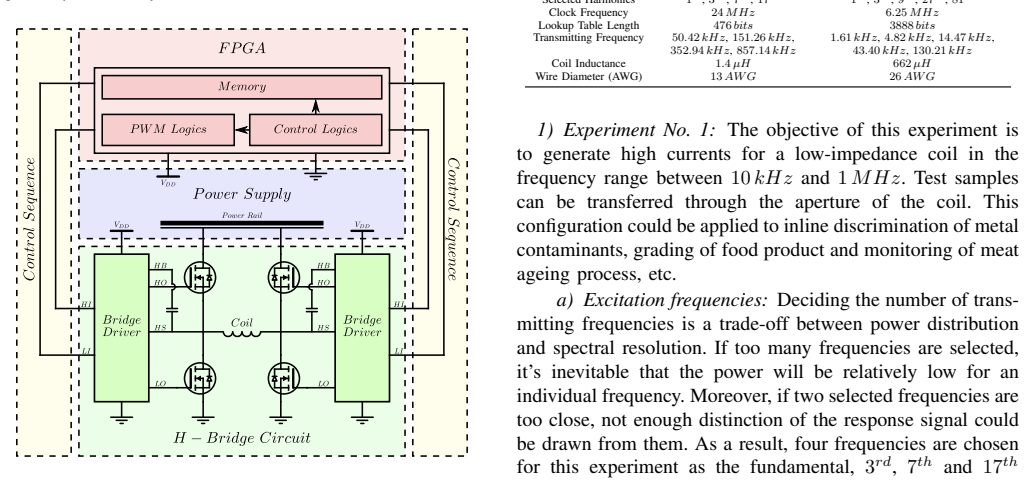
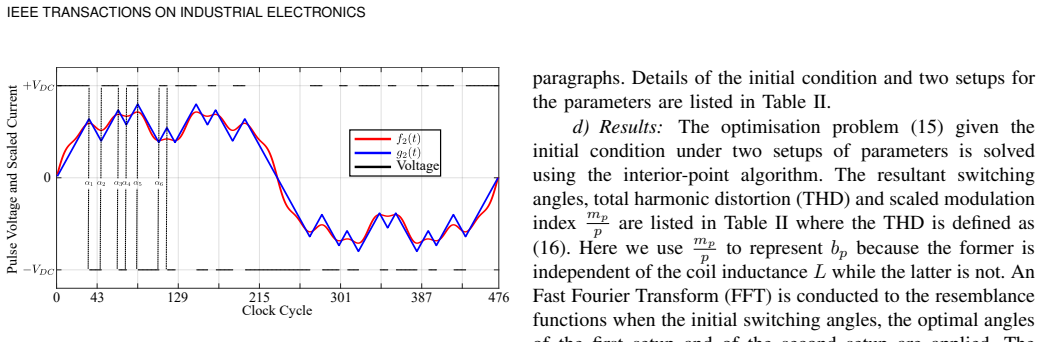
The load-bearing identity is the Fourier-coefficient formula (Eq. 8) for the coil current of a multi-level Class D amplifier: b_p = −4V0/($p^{2}$ π ω L) Σ_{q=1}^{N} (−1)^s sin(p α_q), where α_q are the N switching angles in a quarter period, V0 is the voltage step per level, ω is the fundamental angular frequency, and L is the coil inductance. SHEPWM, selective harmonic elimination pulse width modulation, is a switching strategy that sets pulse-edge positions so that specific output harmonics are controlled. The formula turns the modulation problem into a constrained, non-convex trigonometric optimization over the α_q and the modulation indices m_p: selected harmonics are pulled toward their target amplitudes with weights λ_p, and unselected harmonics are bounded by thresholds ϵ_p (Eq. 9). The method's operating principle is that the coil current is the integral of the pulse voltage across an inductor, so a piecewise-linear approximation of the target multi-sine current is produced directly by the switching waveform. The optimization is solved by an interior-point algorithm initialized at the turning points of the target waveform, and the resulting angles are stored as a lookup table that an FPGA reads to produce the PWM pulses.
What would settle it
Measure the transmitting coil's complex impedance at each transmitted frequency, recompute the harmonic currents from the optimized pulse voltage using that measured impedance (resistor in series with the inductance) instead of a pure inductor, and compare with the FFT of the measured coil current; a systematic mismatch at the higher frequencies would show that the pure-inductor assumption underlying the switching-angle design does not hold.
Extended reading notes
Core claim
The central discovery is that selective harmonic elimination PWM can be repurposed from suppressing harmonics to generating a deliberate superposition of them. The design starts with a target coil current f(t) made of a fundamental and several of its harmonics, with amplitudes w_p chosen (here as 1/p) so higher transmitted frequencies receive proportionally more excitation. This target is approximated by a piecewise-linear current g(t), which is what a pulse voltage across a pure inductor produces; the Fourier coefficients of g(t) are then written as an explicit function of the switching angles α_q and the coil inductance L (Eq. 8). A constrained nonlinear least-squares problem (Eq. 9) tunes the angles so that the selected harmonics match the desired amplitudes while unselected harmonics stay below given thresholds, and the paper solves it with an interior-point algorithm initialized from the turning points of the target waveform. Two FPGA-driven H-bridge experiments verify the method: one reaches 60 A peak-to-peak across a 1.4 µH coil with four simultaneous frequencies and about 8% THD, the other drives a 662 µH coil with five frequencies using only the initial switching-angle guess, skipping the optimization entirely. Measured drain efficiencies of about 20% and 77% in the two experiments, and an energy conversion factor ζ above unity, quantify the power behavior: the lossy coil gives high efficiency, while the high-Q coil gives low efficiency but still delivers over six times the dc input as reactive power to the coil.
Load-bearing premise
The load-bearing premise is that the transmitting coil behaves as a pure inductor, so the coil current is exactly the integral of the applied pulse voltage divided by L; the paper does not quantitatively test how much the coil's resistance and eddy-current loading distort the designed harmonic amplitudes.
Editorial extensions
If this is right
- A single switch-mode amplifier can replace the multiple linear power amplifiers that a multi-frequency eddy current testing system would otherwise need, cutting size, cost, and heat dissipation.
- The excitation spectrum becomes software-reconfigurable: changing the stored lookup table of switching angles changes which harmonics are transmitted, so one hardware design can serve different inspection tasks.
- Because harmonic content above the highest selected frequency is already low in the first experiment, a low-pass output filter can often be omitted.
- The optimization recipe, including the deliberate relaxation of the highest-frequency 'benign ripple' component, provides a practical way to balance amplitude accuracy against total harmonic distortion in similar inductive sensing systems.
- The measured drain efficiency of about 77% in a lossy-coil configuration indicates switch-mode MSF excitation is feasible for battery-powered or thermally constrained instruments.
Reading between the lines
- The same synthesis should also work with arbitrary relative phases among the transmitted frequencies, since the Fourier-coefficient formula already depends on the switching angles; phase-shaped spectra such as the paper's f5(t) example would then be realizable, enabling phase-coded multi-frequency excitation.
- The 1/p amplitude weighting is a design choice; in a specific inspection task, the weights could be optimized to match the sensitivity of the coil-sample coupling, improving the signal-to-noise ratio at each transmitted frequency.
- If the pure-inductor assumption proves inaccurate at high frequencies, a direct extension would be to measure the coil impedance and fold it into the optimization, effectively pre-distorting the switching angles to compensate for resistance and eddy-current loading.
- The method appears transferable to other multi-frequency inductive sensing applications, such as magnetic induction spectroscopy in the beta-dispersion range, where the same frequency-selection logic applies.
Signed reviews
Editorial analysis
A structured set of objections, weighed in public.
Referee Report
Summary. The paper proposes a modulation strategy, MSF-SHEPWM, for a class-D power amplifier intended to drive eddy-current testing coils with a multi-simultaneous-frequency current. The method synthesizes an objective coil current as a sum of selected harmonics, approximates it by a piecewise-linear waveform, computes the Fourier coefficients of the coil current under the assumption that the coil is an ideal inductor, and then solves a constrained optimization problem for the PWM switching angles. Two experiments are reported: an FPGA-driven full H-bridge feeding a 1.4 µH coil at four simultaneous frequencies (about 50 kHz to 857 kHz), and a second experiment feeding a 662 µH coil at five simultaneous frequencies (about 1.6 kHz to 130 kHz). Measured FFT spectra show that the intended harmonics dominate the coil current, and the paper reports efficiency and reactive-power metrics for both cases.
Significance. If the optimization problem were well posed, the paper would make a useful contribution. The idea of deliberately repurposing SHEPWM from fundamental-frequency control and harmonic elimination to simultaneous multi-harmonic synthesis for eddy-current testing addresses a real gap in switch-mode MECT excitation, and the FPGA prototype plus the two sets of measured spectra are valuable evidence that the physical approach can work. The paper also reports data tables and an explicit power/efficiency comparison, which supports reproducibility of the hardware results. However, the central formulation as printed is degenerate because the target modulation indices are treated as free optimization variables, so the stated problem does not enforce the desired spectrum. This affects the main algorithmic claim of the paper and must be fixed before the method can be assessed.
major comments (3)
- [Eq. (9), Eq. (15), Section II-C] The optimization problem (9) lists the modulation indices m_p among the decision variables, and the paragraph following Eq. (9) states that mp is treated as an optimizing parameter. With m_p free, the objective sum_{p in Phi} lambda_p ((p omega L / V0) b_p - m_p)^2 can be made exactly zero for any switching-angle vector by choosing m_p = (p omega L / V0) b_p. The selected-harmonic terms therefore impose no constraint on the solution, and the only active constraints are the inequality bounds on the eliminated set Psi. The same degeneracy appears in the concrete problem (15) of Experiment 1. As written, the optimization does not enforce the intended power distribution among the selected frequencies, and the optimal angle sets in Table II are not the solution of a well-posed problem that controls those harmonics. The manuscript must either remove m_p from the decision variables and specify fixed target values for the selected-harmonic amplitudes, or add explicit equality constraints that tie m_p to prescribed targets, and then re-report the optimization and its results accordingly.
- [Eq. (8), Table III, Table IV, Table V, Experiment No. 1 and No. 2] The Fourier-coefficient formula (8) is derived under the ideal-inductor assumption that the coil current is exactly the integral of the applied voltage divided by L. The paper does not provide a quantitative comparison of the measured harmonic amplitudes with the values predicted from the computed switching angles. In Experiment 1, the coil dissipates 6.87 W and is driven with 60 A peak-to-peak current, so resistance and eddy-current loading are not negligible a priori; in Experiment 2 the same idealization is used for a 662 µH coil. To support the claim that the optimized angles produce the intended spectrum, the authors should report, for both experiments, the predicted versus measured RMS values (or normalized coefficients) at the selected and eliminated harmonics, including a statement of the resulting amplitude error per harmonic and overall distortion.
- [Section III-C-1, Table II, Experiment No. 2] Experiment 2 deliberately skips the optimization stage and uses only the initial switching angles obtained from the gradient of the objective function. Consequently, the second experiment does not test the proposed optimization formulation at all; it tests only the time-domain synthesis stage. The claim that the full MSF-SHEPWM procedure produces low-distortion multi-frequency currents therefore rests entirely on Experiment 1, whose optimization problem has the degeneracy described above. The paper should either add an experiment that implements the corrected optimization, or clearly separate the two claims and identify which stage each experiment validates.
minor comments (4)
- [Eq. (15)] There is a sign inconsistency between the normalized coefficient in Eq. (14) and the expression in Eq. (15): Eq. (14) yields a negative scaled coefficient, while Eq. (15) writes the residual with a plus sign before m_p. If m_p is intended as a positive amplitude, the objective should use the absolute value or an explicitly signed form so that the optimization problem matches the physical meaning of the modulation index.
- [Section II-C] The sentence 'if annulation of the objective function is not possible' contains a typographical error; 'annulation' should be 'annihilation' or 'nullification'.
- [Section II-A] The phrase 'the coefficient wp is chosen as 1/p for the selected frequencies' is stated before any motivation; it would be clearer to present the SNR-based motivation together with the definition, since this choice is central to all subsequent examples.
- [Table II and Eq. (16)] Table II reports the scaled modulation index mp/p for the selected harmonics but no target values for these quantities; a column of target normalized coefficients would make the optimization results interpretable even after the m_p issue is resolved.
Circularity Check
Eq. (9) makes the selected-harmonic modulation index a free optimization variable, so the residual is identically zero and the claimed harmonic-control optimization does not impose the desired spectrum.
-
self definitional
[Section II-C, Eq. (9) and surrounding text]
"min_{0≤α1≤α2≤···≤αN≤π/2, mp} ∑_{p∈Φ} λ_p ((pωL/V0) b_p − m_p)^2, subject to |(pωL/V0) b_p| ≤ ε_p, ∀p∈Ψ ... The optimising parameters are N switching angles α1, α2, ···, αN and the modulation index mp."
Because m_p is one of the optimization variables, for every switching-angle vector α the solver can choose m_p = (pωL/V0)b_p, making every selected-harmonic residual exactly zero. The objective function is therefore identically zero at its global minimum regardless of α, so Eq. (9) imposes no constraint on the amplitudes of the selected harmonics. The only active requirements are the inequality bounds on the eliminated harmonics in Ψ. The paper's later Table II reports scaled modulation indices m_p/p, but these are simply the post-hoc normalized values of the optimized b_p, not externally prescribed targets.
full rationale
The paper does contain independent, non-circular content: Eq. (8) is a standard Fourier-coefficient calculation for piecewise-linear coil current, and the measured FFT spectra in Tables III and IV are external experimental evidence that the implemented switching patterns produce multi-frequency currents. The ideal-inductor assumption in Eq. (8) is a modeling risk rather than a circularity. However, the central optimization step that is presented as the mechanism for controlling the selected harmonic spectrum is degenerate as written. Since m_p is free, the objective in Eq. (9) can always be zeroed by setting m_p equal to the scaled actual harmonic coefficient, so the selected harmonics are not pinned to any independent target. This is a self-definitional/fitted-input circularity: the quantity being optimized appears as its own target. The paper's reported 'optimized' switching angles therefore cannot be said, on the basis of Eq. (9), to enforce the intended 1/p spectral weighting. The experimental demonstration is suggestive, but the design step that is claimed to produce the desired spectrum is not logically independent of the result it claims to predict.
Assumptions & free parameters
free parameters (4)
- Desired spectral weights w_p = 1/p
- Constraint thresholds epsilon_p =
0.10, 0.18, 0.22, 0.26, 0.30 for p=5,9,11,13,15 (Exp. 1)
- Objective weights lambda_p =
lambda_1..lambda_7=1, lambda_17=0 in Setup 2
- Modulation indices m_p =
m_p/p values in Table II, e.g., 0.553, 0.171, 0.047, 0.032
assumptions (4)
- domain assumption The transmitting coil is a pure inductor, so the coil current is the integral of the applied pulse voltage divided by L (Eq. 8).
- domain assumption Selected excitation components are integer harmonics of a common fundamental with zero relative phase (Eq. 1 with w_p=1/p).
- standard math The interior-point algorithm (fmincon) finds a switching-angle solution with acceptable residuals despite the non-convex problem.
- domain assumption A full H-bridge with bipolar three-level voltage is sufficient to approximate the objective current with tolerable error.
Cite this review
Pith. "Pith review of A Class D Power Amplifier for Multi-Frequency Eddy Current Testing Based on Multi-Simultaneous-Frequency Selective Harmonic Elimination Pulse Width Modulation." pith.science (2026). https://pith.science/paper/YHMXT3LU
@misc{pith2026190808535,
  author       = {Pith},
  title        = {Pith review of: A Class D Power Amplifier for Multi-Frequency Eddy Current Testing Based on Multi-Simultaneous-Frequency Selective Harmonic Elimination Pulse Width Modulation},
  year         = {2026},
  howpublished = {\url{https://pith.science/paper/YHMXT3LU}},
  note         = {Machine review of arXiv:1908.08535}
}
read the original abstract
Efficiency and multisimultaneous-frequency (MSF) output capability are two major criteria characterizing the performance of a power amplifier in the application of multifrequency eddy current testing (MECT). Switch-mode power amplifiers are known to have a very high efficiency, yet they have rarely been adopted in the instrumental development of MECT. In addition, switch-mode power amplifiers themselves are lacking in the research literature for MSF capability. In this article, a Class D power amplifier is designed so as to address the two issues. An MSF selective harmonic elimination pulsewidth modulation method is proposed to generate alternating magnetic fields, which are rich in selected harmonics. A field-programmable-gate-array-based experimental system has been developed to verify the design. Results show that the proposed methodology is capable of generating high MSF currents in the transmitting coil with a low distortion of signal.
Figures


Figures from the paper (8 more)



Reference graph
Works this paper leans on
-
[1]
Crack Depth Esti- mation by Using a Multi-Frequency ECT Method,
A. Bernieri, G. Betta, L. Ferrigno, and M. Laracca, “Crack Depth Esti- mation by Using a Multi-Frequency ECT Method,” IEEE Transactions on Instrumentation and Measurement , vol. 62, no. 3, pp. 544–552, Mar. 2013
work page 2013
-
[2]
Thickness measurement of non-magnetic plates using multi-frequency eddy current sensors,
W. Yin and A. J. Peyton, “Thickness measurement of non-magnetic plates using multi-frequency eddy current sensors,” NDT & E Interna- tional, vol. 40, no. 1, pp. 43–48, Jan. 2007
work page 2007
-
[3]
Using electromagnetic methods to monitor the transformation of steel samples,
S. Johnstone, R. Binns, A. J. Peyton, and W. D. Pritchard, “Using electromagnetic methods to monitor the transformation of steel samples,” Transactions of the Institute of Measurement and Control, vol. 23, no. 1, pp. 21–29, Mar. 2001. IEEE TRANSACTIONS ON INDUSTRIAL ELECTRONICS
work page 2001
-
[4]
W. Yin, S. Dickinson, and A. Peyton, “Imaging the continuous con- ductivity profile within layered metal structures using inductance spec- troscopy,”IEEE Sensors Journal, vol. 5, no. 2, pp. 161–166, Apr. 2005
work page 2005
-
[5]
Non- Destructive Techniques Based on Eddy Current Testing,
J. García-Martín, J. Gómez-Gil, and E. Vázquez-Sánchez, “Non- Destructive Techniques Based on Eddy Current Testing,” Sensors, vol. 11, no. 3, pp. 2525–2565, Feb. 2011
work page 2011
-
[6]
Multilevel inverters: a survey of topologies, controls, and applications,
J. Rodriguez, J.-S. Lai, and F. Z. Peng, “Multilevel inverters: a survey of topologies, controls, and applications,” IEEE Transactions on Industrial Electronics, vol. 49, no. 4, pp. 724–738, Aug. 2002
work page 2002
-
[7]
A Survey on Cascaded Multilevel Inverters,
M. Malinowski, K. Gopakumar, J. Rodriguez, and M. Pérez, “A Survey on Cascaded Multilevel Inverters,” IEEE Transactions on Industrial Electronics, vol. 57, no. 7, pp. 2197–2206, Jul. 2010
work page 2010
-
[8]
M. S. A. Dahidah, G. Konstantinou, and V . G. Agelidis, “A Review of Multilevel Selective Harmonic Elimination PWM: Formulations, Solving Algorithms, Implementation and Applications,” IEEE Transactions on Power Electronics, vol. 30, no. 8, pp. 4091–4106, Aug. 2015
work page 2015
Show all 19 references
-
[9]
Selective Harmonic Mitigation Technique for High-Power Converters,
J. Napoles, J. I. Leon, R. Portillo, L. G. Franquelo, and M. A. Aguirre, “Selective Harmonic Mitigation Technique for High-Power Converters,” IEEE Transactions on Industrial Electronics , vol. 57, no. 7, pp. 2315– 2323, Jul. 2010
2010
-
[10]
Control of a multilevel converter using resultant theory,
J. N. Chiasson, L. M. Tolbert, K. J. McKenzie, and Z. Du, “Control of a multilevel converter using resultant theory,” IEEE Transactions on Control Systems Technology, vol. 11, no. 3, pp. 345–354, May. 2003
2003
-
[11]
Application of differential evolution for cascaded multilevel VSI with harmonics elimination PWM switching,
A. M. Amjad, Z. Salam, and A. M. A. Saif, “Application of differential evolution for cascaded multilevel VSI with harmonics elimination PWM switching,” International Journal of Electrical Power & Energy Systems, vol. 64, pp. 447–456, Jan. 2015
2015
-
[12]
Switched- Battery Boost-Multilevel Inverter with GA Optimized SHEPWM for Standalone Application,
S. S. Lee, B. Chu, N. R. N. Idris, H. H. Goh, and Y . E. Heng, “Switched- Battery Boost-Multilevel Inverter with GA Optimized SHEPWM for Standalone Application,” IEEE Transactions on Industrial Electronics , vol. 63, no. 4, pp. 2133–2142, Apr. 2016
2016
-
[13]
Harmonic Elimination of Cascade Multilevel Inverters with Nonequal DC Sources Using Particle Swarm Optimization,
H. Taghizadeh and M. T. Hagh, “Harmonic Elimination of Cascade Multilevel Inverters with Nonequal DC Sources Using Particle Swarm Optimization,” IEEE Transactions on Industrial Electronics , vol. 57, no. 11, pp. 3678–3684, Nov. 2010
2010
-
[14]
S. P. Boyd and L. Vandenberghe, Convex optimization . New York: Cambridge University Press, 2004
2004
-
[15]
Nesterov and A
Y . Nesterov and A. Nemirovskii, Interior-Point Polynomial Algorithms in Convex Programming, ser. Studies in Applied and Numerical Mathemat- ics. Philadelphia, USA: Society for Industrial and Applied Mathematics, Jan. 1994
1994
-
[16]
Eroglu, Introduction to RF Power Amplifier Design and Simulation
A. Eroglu, Introduction to RF Power Amplifier Design and Simulation . Boca Raton: CRC Press, 2015
2015
-
[17]
Power measurement techniques for non-sinusoidal con- ditions,
S. Svensson, “Power measurement techniques for non-sinusoidal con- ditions,” Ph.D. dissertation, Department of Electric Power Engineering, Chalmers University of Technology, 1999
1999
-
[18]
Non-contact multi-frequency magnetic induction spectroscopy system for industrial-scale bio-impedance measurement,
M. D. O’Toole, L. A. Marsh, J. L. Davidson, Y . M. Tan, D. W. Armitage, and A. J. Peyton, “Non-contact multi-frequency magnetic induction spectroscopy system for industrial-scale bio-impedance measurement,” Measurement Science and Technology , vol. 26, no. 3, p. 035102, 2015
2015
-
[19]
A Thickness Measurement System for Metal Films Based on Eddy-Current Method With Phase Detection,
W. Li, Y . Ye, K. Zhang, and Z. Feng, “A Thickness Measurement System for Metal Films Based on Eddy-Current Method With Phase Detection,” IEEE Transactions on Industrial Electronics , vol. 64, no. 5, pp. 3940– 3949, May. 2017. Yang Tao (M’19) received the B.Sc. degree in autom...
2017
Reviewed August 14, 2026 · model on record in the stance chip above.
Discussion (0). Continue with ORCID to comment.