REVIEW 3 major objections 5 minor 28 references
Heterogeneous porous scaffold generation in trivariate B-spline solid with triply periodic minimal surface in the parametric domain
T0 review · 3 major / 5 minor · reviewed 2026-08-14 · deepseek-v4-flash
Pith's one-line read A trivariate B-spline solid can carry a heterogeneous porous scaffold by mapping a triply periodic minimal surface from the parametric domain, yielding complete, continuous pore units with porosity set by a threshold distribution field.
desk verdict The construction is sound and the completeness/continuity claims are real, but the porosity-control claim is not measured in the mapped scaffolds and needs validation before publication. read the letter →
The pith
A machine-rendered reading of the paper's core claim, the machinery that carries it, and where it could break.
The reading
What carries the argument
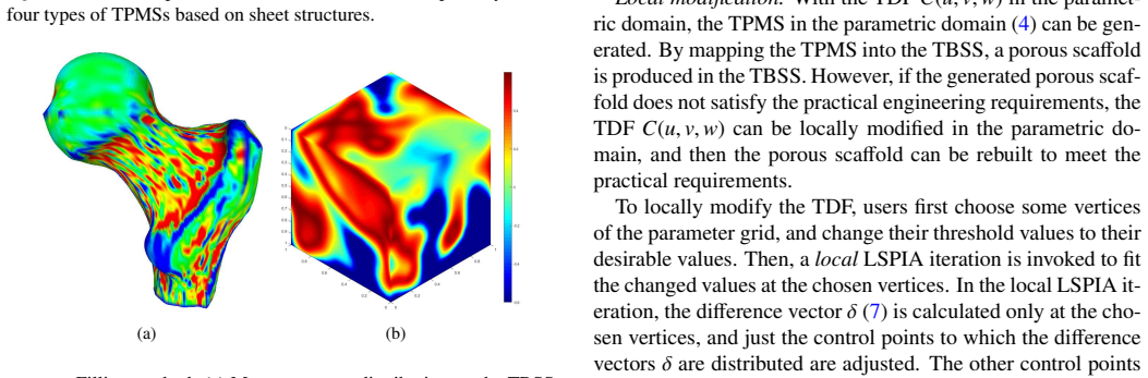
The threshold distribution field (TDF), a trivariate B-spline function $C(u,v,w)$ fitted by least-squares progressive-iteration approximation (LSPIA) on a parametric grid, is the control mechanism: it converts the constant threshold in the TPMS equation into a spatially varying one, so the iso-surface $\psi=C$ becomes a heterogeneous surface whose local pore size follows the field. The second element is the mapping through the TBSS function $P(u,v,w)$, which carries the parametric TPMS into the physical solid; a positive Jacobian of the TBSS ensures the map is fold-free, which is what preserves completeness and continuity in the final scaffold.
What would settle it
Measure the actual porosity of a mapped scaffold, for example by voxelizing the final triangular mesh and counting the solid fraction, and compare it with the porosity predicted from the TDF calibration curves; if the mismatch exceeds a practical tolerance across a strongly deformed TBSS region, the porosity-control claim fails.
Extended reading notes
Core claim
The central claim is that a heterogeneous porous scaffold with complete, continuous TPMS units is produced by defining the TPMS in the parameter domain of a TBSS and mapping it to the physical domain. The TPMS is given implicitly by $f(u,v,w)=\psi(u,v,w)-C(u,v,w)=0$, where $\psi$ is a nodal approximation of a TPMS and $C$ is a trivariate B-spline TDF whose values set local pore size; the scaffold is the image of the volume bounded by this surface under the TBSS mapping. Completeness follows because the parametric TPMS is a single surface covering the whole domain, so no unit is cut off at the boundary, and continuity follows because adjacent 'units' are just portions of that same surface. The paper further claims the TDF file format—storing period coefficients, TDF control points and knots, and TBSS control points and knots—reproduces the scaffold at any resolution and cuts storage by roughly two orders of magnitude compared with STL.
Load-bearing premise
The porosity-versus-threshold curves measured on the uniform parametric grid are assumed to still give the correct porosity after the TPMS is deformed through the trivariate B-spline solid into the physical shape, but the paper never measures the porosity of the final mapped scaffolds to check.
Editorial extensions
If this is right
- Any TBSS with positive Jacobian can be turned into a heterogeneous scaffold whose TPMS units are complete and continuous, eliminating the two reported defects of hexahedral-mesh and T-spline embedding methods.
- Pore size becomes a design variable: editing the TDF in the parameter domain, for example by local LSPIA updates, rebuilds the scaffold locally without redoing the whole generation.
- The TDF file format stores the scaffold parametrically, so the same file can generate meshes at any prescribed precision, and storage drops from hundreds of megabytes to about one megabyte.
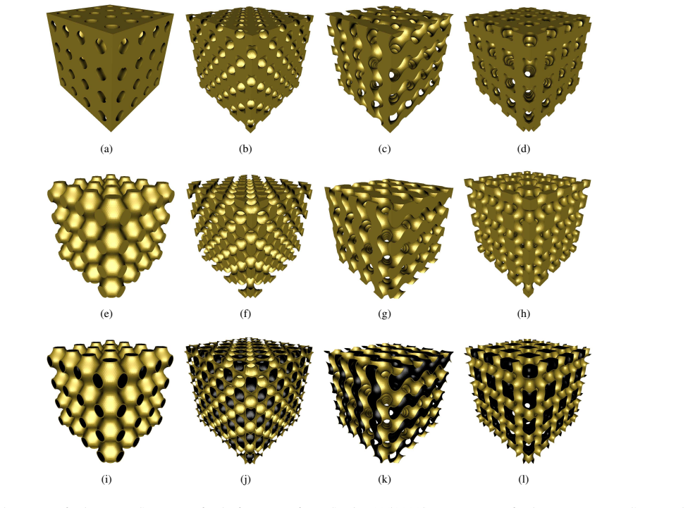
- The same pipeline extends to pore, rod, and sheet structure types and to P, D, G, and I-WP TPMSs, provided the threshold stays in the valid range for that surface.
Reading between the lines
- If the porosity calibration curves are not re-verified in the deformed physical domain, the quantitative porosity-control claim may fail under strong TBSS distortion; a natural extension is to measure porosity of the mapped scaffold and adjust the TDF-to-threshold mapping accordingly.
- The parametric storage suggests a design-optimization loop in which the TDF control points and period coefficients act as free parameters, letting an optimizer tune pore-size distribution without ever exporting a mesh.
- The same 'generate in parameter space, map to solid' trick could work for other implicit structures, such as Voronoi-like level sets or lattice functions, not only TPMSs, whenever the solid is given as a spline volume.
Signed reviews
Editorial analysis
A structured set of objections, weighed in public.
Referee Report
Summary. The paper proposes a method for generating heterogeneous porous scaffolds inside a trivariate B-spline solid (TBSS). The key idea is to construct a threshold distribution field (TDF) C(u,v,w) over the cubic parameter domain of the TBSS, define a TPMS as the level set ψ(u,v,w) = C(u,v,w), polygonize it with marching tetrahedra, and map the resulting surface and volume structures through the TBSS to obtain a porous scaffold. The authors claim three main contributions: (1) guaranteed completeness of TPMS units and continuity between them, (2) easy porosity control via the TDF, and (3) a compact 'TDF' file format that stores the scaffold as a procedural representation rather than a mesh. The paper includes several examples (ball joint, Venus, Moai, tooth, Isis) and a comparison with two prior methods, claiming storage savings of at least 98% over STL. The completeness and continuity claims are argued from the positive-Jacobian mapping of a unitary TPMS, and the storage format is presented with an appendix. However, the paper does not quantitatively verify that the porosity of the final mapped scaffolds matches the intended TDF-derived distribution.
Significance. If the claims are validated, the method would address three recognized drawbacks of TPMS-based scaffold design: broken boundary units, discontinuities between adjacent units, and large file sizes. The parametric-domain construction with a positive-Jacobian TBSS mapping is a conceptually clean way to guarantee completeness and continuity, and the procedural TDF file format is a practical contribution that could benefit downstream fabrication and interactive design. The local TDF modification workflow adds useful flexibility. The porosity-control claim, however, is the central quantitative assertion of the paper, and it is currently supported only by calibration curves computed on a uniform parametric domain, with no measured verification on the deformed physical scaffolds. The absence of such validation leaves the primary contribution only partially established, though the issue appears addressable with additional experiments or a Jacobian-aware calibration.
major comments (3)
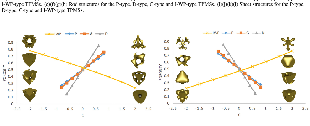
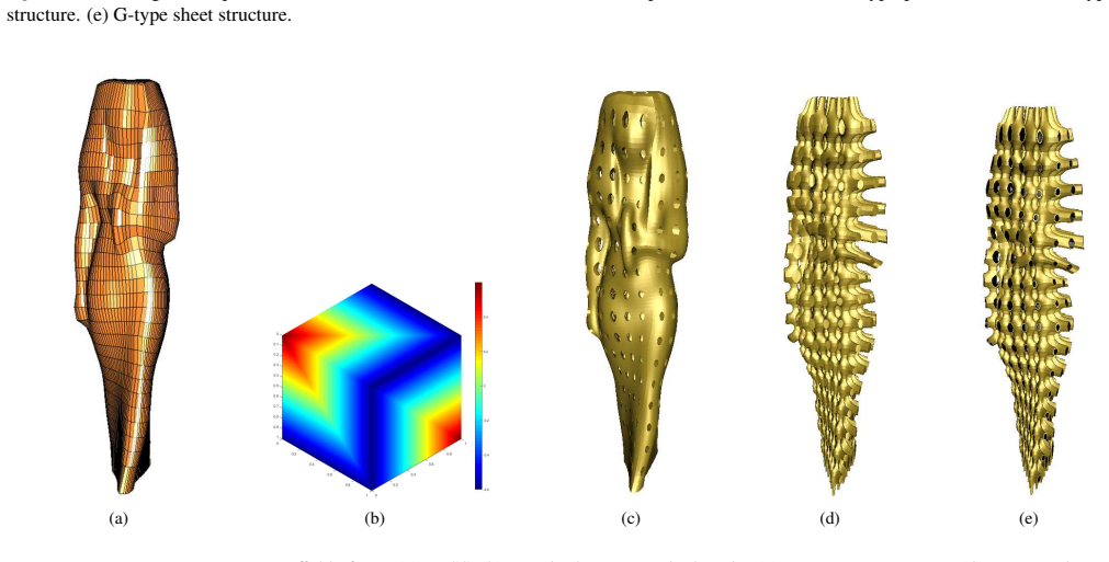
- [§3.2, Figs. 4-6, Eq. (4)] The porosity-threshold calibration curves in Figs. 4-6 are computed for a uniform cubic cell in the parametric domain. After mapping through the TBSS (Eq. (2)), the physical volume fraction of the set {ψ ≥ C} is ∫_{ψ≥C} |J| du dv dw / ∫ |J| du dv dw, where |J| is the Jacobian determinant. For a TBSS with non-constant Jacobian, the calibration curves do not directly predict physical porosity. The paper never reports the measured porosity of the final scaffolds in Figs. 13-17 or compares it with the intended TDF-derived distribution, so the claim that porosity is controlled by the TDF is not quantitatively established. Please provide physical-domain porosity measurements (e.g., by voxelizing the mapped scaffold and computing the volume fraction) for the presented examples, or alternatively restrict the method to TBSSs with constant Jacobian, or provide a Jacobian-corrected calibration procedure.
- [§3.2, Eqs. (5)-(10)] The TDF is obtained by least-squares progressive-iteration approximation (LSPIA) fitting of discrete threshold values on a 50×50×50 grid with a 20×20×20 control grid. The fitting error is not quantified. Since the TPMS is defined by ψ(u,v,w) - C(u,v,w) = 0, approximation errors in C directly shift the level surface and hence change the porosity. The convergence proof cited in [28] does not provide a concrete error bound for this particular fitting problem. The paper should report the fitting error (e.g., max and RMS error between the fitted B-spline and the discrete TDF) and, if possible, analyze its impact on the resulting porosity.
- [§3.4 and Appendix] The proposed TDF file format as described stores the period coefficients, the control points and knot vectors of the TDF, and the control points and knot vectors of the TBSS, but it does not store the TPMS type (P, D, G, or I-WP) or the structure type (pore, rod, or sheet). These fields are essential for reconstructing the scaffold from the file; without them the same stored data could produce different scaffolds. The format appendix should be completed by adding these fields, and the text in §3.4 should list them as part of the stored information.
minor comments (5)
- [§3.2] The computation method for the porosity-threshold curves in Figs. 4-6 is not stated (e.g., voxel grid resolution, or whether the volume fraction is computed from the marching-tetrahedra mesh or by numerical integration). Please state the method for reproducibility.
- [§3.2, Eq. (8)] The notation in Eq. (8) is confusing: the index set Iαβγ is defined by the condition Ni,p(uα)Nj,q(vβ)Nk,r(wγ) ≠ 0, but the summation uses I ∈ Iαβγ and evaluates the basis functions at (uI, vI, wI). The set should be defined as the set of grid nodes in the support of the (i,j,k)-th basis function, and the sum should run over those nodes. Please clarify the notation.
- [§3.1] The closing procedure for volume structures adds 'outside triangles' on the boundary faces when all vertices satisfy ψ ≥ C. This works if the iso-surface ψ = C does not pass through grid vertices; otherwise ambiguous cases may arise. A short comment on this assumption or a note on handling degenerate cases would be useful.
- [§4.1] The statement 'The larger the value of C(u,v,w), the larger the pore size' is valid for pore structures but is reversed for rod structures. Please qualify the statement to avoid ambiguity.
- [Throughout] Several typographical errors and formatting issues need correction, including 'compeleteness' in Section 3, 'ja:math' in reference [21], and inconsistent spacing in equations. A careful proofreading pass is recommended.
Circularity Check
No circularity found: the TDF, TPMS, and TBSS mapping are design inputs and constructions, not predictions fitted to or defined by their outputs.
full rationale
The paper's derivation chain is constructive: the user or geometry prescribes discrete threshold values; LSPIA fits these into a B-spline TDF; the TPMS is defined by f = psi(u,v,w) - C(u,v,w) = 0 in the parameter domain; marching tetrahedra polygonizes this level set; and the positive-Jacobian TBSS mapping transfers the parametric volume TPMS structure to physical space. Every step uses externally established mathematical tools (nodal TPMS approximations from Ref. [4], marching tetrahedra from Ref. [23], LSPIA convergence from Ref. [28]). The porosity/threshold curves in Figs. 4-6 are computed from the defining level-set relation rather than fitted to data, so no fitted parameter is relabeled as a prediction. The completeness and continuity claims follow from mapping a single unitary parametric TPMS through a bijective, positive-Jacobian TBSS, not from matching any measured output. The TDF file format comparison against STL is a direct storage measurement. The only self-citation, Ref. [28] (LSPIA), is used as an approximation subroutine; the central claims do not reduce to that citation, and its convergence result is independent published mathematics. A legitimate empirical concern remains: physical porosity after mapping is not measured, and the parametric calibration does not account for the Jacobian weight in the physical volume integral, so the quantitative porosity claim is not validated in the deformed solid. That is a correctness/validation gap, not a circularity, and it does not affect the circularity score.
Assumptions & free parameters
free parameters (3)
- Period coefficients (omega_x, omega_y, omega_z) =
Per model: e.g., (16,14,18) for Ball joint, (10,10,10) for Venus
- Parametric grid resolutions =
100x100x100 for polygonization; 50x50x50 for TDF discretization; 20x20x20 for TDF control grid
- Valid threshold ranges =
P: [-0.8,0.8], D: [-0.6,0.6], G: [-0.8,0.8], I-WP: [-2.0,2.0]
assumptions (4)
- standard math B-spline basis functions and LSPIA fitting converge to a least-squares fit (Ref. [20,28]).
- domain assumption The nodal approximations of the four TPMS types (Table 1) and their valid C ranges are accurate enough for scaffold design.
- domain assumption The input TBSS has positive Jacobian in its parametric domain (Section 3.3).
- domain assumption The marching tetrahedra algorithm on a 100x100x100 grid captures the TPMS topology at a resolution acceptable for the examples.
Cite this review
Pith. "Pith review of Heterogeneous porous scaffold generation in trivariate B-spline solid with triply periodic minimal surface in the parametric domain." pith.science (2026). https://pith.science/paper/ZYJ34F6U
@misc{pith2026190801938,
  author       = {Pith},
  title        = {Pith review of: Heterogeneous porous scaffold generation in trivariate B-spline solid with triply periodic minimal surface in the parametric domain},
  year         = {2026},
  howpublished = {\url{https://pith.science/paper/ZYJ34F6U}},
  note         = {Machine review of arXiv:1908.01938}
}
read the original abstract
A porous scaffold is a three-dimensional network structure composed of a large number of pores, and triply periodic minimal surfaces (TPMSs) are one of conventional tools for designing porous scaffolds. However, discontinuity, incompleteness, and high storage space requirements are the three main shortcomings of TPMSs for porous scaffold design. In this study, we developed an effective method for heterogeneous porous scaffold generation to overcome the abovementioned shortcomings of TPMSs. The input of the proposed method is a trivariate B-spline solid (TBSS) with a cubic parameter domain. The proposed method first constructs a threshold distribution field (TDF) in the cubic parameter domain, and then produces a continuous and complete TPMS within it. Moreover, by mapping the TPMS in the parametric domain to the TBSS, a continuous and complete porous scaffold is generated in the TBSS. In addition, if the TBSS does not satisfy engineering requirements, the TDF can be locally modified in the parameter domain, and the porous scaffold in the TBSS can be rebuilt. We also defined a new storage space-saving file format based on the TDF to store porous scaffolds. The experimental results presented in this paper demonstrate the effectiveness and efficiency of the method using a TBSS as well as the superior space-saving of the proposed storage format.
Figures


Figures from the paper (12 more)



Reference graph
Works this paper leans on
-
[28]
C. Deng, H. Lin, Progressive and iterative approximation for least squares b-spline curve and surface fitting, Computer-Aided Design 47 (1) (2014) 32–44. Appendix: TDF file format #period coefficients(ωx,ω y,ω z) ωxωyωz #resolution of control grid of TDF nu + 1 nv + 1 nw + 1 #control points of TDF C0,0,0 C0,0,1 ... Cnu,nv,nw #knot vector in u-direction of TDF...
work page 2014
-
[1]
D. W. Hutmacher, Sca ffolds in tissue engineering bone and cartilage., Biomaterials 21 (24) (2000) 2529–2543
work page 2000
-
[2]
B. Starly, C. Gomez, A. Darling, Z. Fang, A. Lau, W. Sun, W. Lau, T. Bradbury, A. Youssef, C. Gaylo, Computer-aided bone sca ffold de- sign: a biomimetic approach, in: 2003 IEEE 29th Annual Proceedings of Bioengineering Conference, 2003, pp. 172–173. 9 (a) (b) (c) (d) (e) Figure 13: Heterogeneous porous scaffold of Ball-joint. (a) TBSS. (b) TDF in the param...
work page 2003
- [3]
-
[4]
H. G. V . Schnering, R. Nesper, Nodal surfaces of fourier series: Funda- mental invariants of structured matter, Zeitschrift Fr Physik B Condensed Matter 83 (3) (1991) 407–412
work page 1991
-
[5]
D. Yoo, Porous sca ffold design using the distance field and triply periodic minimal surface models, Biomaterials 32 (31) (2011) 7741–7754
work page 2011
-
[6]
D. Yoo, Heterogeneous minimal surface porous sca ffold design using the distance field and radial basis functions, Medical Engineering & Physics 10 (a) (b) (c) (d) (e) Figure 16: Heterogeneous porous sca ffold of Tooth. (a) TBSS. (b) TDF in the parametric domain. (c) G-type pore structure. (d) G-type rod structure. (e) G-type sheet structure. (a) (b) (c) (d)...
work page 2012
-
[7]
N. Yang, K. Zhou, E ffective method for multi-scale gradient porous scaffold design and fabrication., Materials Science & Engineering C 43 (2014) 502–505
work page 2014
Show all 28 references
-
[8]
J. Feng, J. Fu, C. Shang, Z. Lin, B. Li, Porous sca ffold design by solid t-splines and triply periodic minimal surfaces, Computer Methods in Ap- plied Mechanics & Engineering 336 (2018) 333–352
2018
-
[9]
D. Yoo, Computer-aided porous sca ffold design for tissue engineering us- ing triply periodic minimal surfaces, International Journal of Precision Engineering & Manufacturing 12 (1) (2011) 61–71
2011
-
[10]
H. Chen, Y . Guo, R. Rostami, S. Fan, K. Tang, Z. Yu, Porous structure de- sign using parameterized hexahedral meshes and triply periodic minimal surfaces, in: Proceedings of Computer Graphics International 2018, CGI 2018, Bintan Island, Indonesia, June 11-14, 2018, ACM Press,...
2018
-
[11]
J. Shi, L. Zhu, L. Li, Z. Li, J. Yang, X. Wang, A tpms-based method for modeling porous scaffolds for bionic bone tissue engineering, Scientific Reports 8 (1) (2018) 7395
2018
-
[12]
Rajagopalan, R
S. Rajagopalan, R. A. Robb, Schwarz meets schwann: design and fabrica- tion of biomorphic tissue engineering scaffolds., Medical Image Analysis 10 (5) (2006) 693–712
2006
-
[13]
F. P. Melchels, K. Bertoldi, R. Gabbrielli, A. H. Velders, J. Feijen, D. W. Grijpma, Mathematically defined tissue engineering sca ffold architec- tures prepared by stereolithography., Biomaterials 31 (27) (2010) 6909– 6916
2010
-
[14]
T. J. R. Hughes, J. A. Cottrell, Y . Bazilevs, Isogeometric analysis: Cad, finite elements, nurbs, exact geometry and mesh refinement, Computer Methods in Applied Mechanics & Engineering 194 (39) (2005) 4135– 4195
2005
-
[15]
Zhang, Y
Y . Zhang, Y . Bazilevs, S. Goswami, C. L. Bajaj, T. J. Hughes, Patient- specific vascular NURBS modeling for isogeometric analysis of blood flow, Computer methods in applied mechanics and engineering 196 (29) (2007) 2943–2959
2007
-
[16]
Martin, E
T. Martin, E. Cohen, R. M. Kirby, V olumetric parameterization and trivariate b-spline fitting using harmonic functions, Computer Aided Ge- ometric Design 26 (6) (2009) 648–664
2009
-
[17]
Aigner, C
M. Aigner, C. Heinrich, B. Jttler, E. Pilgerstorfer, B. Simeon, A. V . Vuong, Swept volume parameterization for isogeometric analysis, in: Mathematics of Surfaces XIII, Springer Berlin Heidelberg, Berlin, Hei- delberg, 2009, pp. 19–44
2009
-
[18]
X. Wang, X. Qian, An optimization approach for constructing trivariate b-spline solids, Computer-Aided Design 46 (1) (2014) 179–191
2014
-
[19]
H. Lin, S. Jin, Q. Hu, Z. Liu, Constructing b-spline solids from tetrahedral meshes for isogeometric analysis, Computer Aided Geometric Design 35- 36 (2015) 109–120
2015
-
[20]
Piegl, Les, W
A. Piegl, Les, W. Tiller, The NURBS Book, Springer Berlin Heidelberg, Berlin, Heidelberg, 1997
1997
-
[21]
P. J. F. Gandy, S. Bardhan, A. L. Mackay, J. Klinowski, Nodal surface 11 approximations to the ja:math and i-wp triply periodic minimal surfaces, Chemical Physics Letters 336 (3) (2001) 187–195
2001
-
[22]
Yan, Periodic surface modeling for computer aided nano design, Computer-Aided Design 39 (3) (2007) 179–189
W. Yan, Periodic surface modeling for computer aided nano design, Computer-Aided Design 39 (3) (2007) 179–189
2007
-
[23]
A. Doi, A. Koide, An e fficient method of triangulating equivalued sur- faces by using tetrahedral cells, Ieice Trans 74 (1) (1991) 214–224
1991
-
[24]
P. L. George, H. Borouchaki, Delaunay Triangulation and Meshing, Paris: ´Edition Herm`es, 1998
1998
-
[25]
W. E. Lorensen, H. E. Cline, Marching cubes: A high resolution 3d sur- face construction algorithm, Acm Siggraph Computer Graphics 21 (4) (1987) 163–169
1987
-
[26]
T. S. Newman, H. Yi, A survey of the marching cubes algorithm, Com- puters & Graphics 30 (5) (2006) 854–879
2006
-
[27]
D. A. Field, Laplacian smoothing and delaunay triangulations, Commu- nications in Applied Numerical Methods 4 (6) (1988) 709–712
1988
Reviewed August 14, 2026 · model on record in the stance chip above.
Discussion (0). Continue with ORCID to comment.