REVIEW 2 major objections 5 minor 1 cited by
Ray-Based Simulation of Scattering from Discretized Curved Bodies for Vehicular and ISAC Applications
T0 review · 2 major / 5 minor · reviewed 2026-07-13 · grok-4.5
Pith's one-line read No single mesh works for both backscattering and shadowing of curved vehicles in ray tracing: fine facets help one region, coarse facets the other.
desk verdict Useful dual-mesh RT result for vehicular/ISAC scattering, with solid multi-reference checks; the shadow gains rest on a flagged heuristic EV/VE cascade that is the real soft spot, not a deal-breaker for practice. read the letter →
The pith
A machine-rendered reading of the paper's core claim, the machinery that carries it, and where it could break.
The reading
What carries the argument
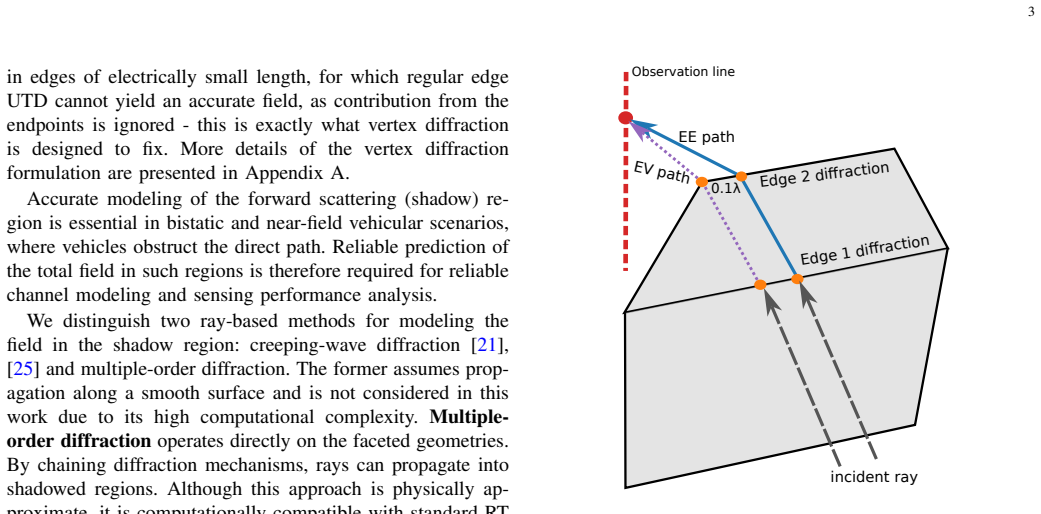
An extended ray-tracing diffraction framework that augments classical UTD edge diffraction with vertex diffraction and second-order paths (double-edge plus a heuristic cascade of edge–vertex and vertex–edge diffraction), together with the mesh metric a^{2}/(R λ) that links facet size a to local radius of curvature R and wavelength.
What would settle it
Recompute the sphere and low-polygon vehicle shadow-region total-field MAE after replacing the heuristic EV/VE cascade with a rigorously uniformized double-diffraction coefficient (or with a full-wave reference that isolates only those paths); if the MAE gains disappear or reverse, the central accuracy claim fails.
Extended reading notes
Core claim
No universal discretization strategy exists for ray-based scattering from curved bodies: fine meshes improve backscattering prediction, while coarser discretizations can be both more efficient and more accurate for shadow-region prediction when an extended Uniform Theory of Diffraction that includes vertex diffraction and double-bounce edge/vertex combinations is used.
Load-bearing premise
The mixed edge–vertex double-diffraction paths that improve the shadow-region numbers rest on a heuristic coefficient cascade that only captures one polarization component and is known to be non-uniform when a double-diffracted ray approaches a shared vertex.
Editorial extensions
If this is right
- Vehicular and ISAC channel simulators can adopt dual-resolution meshes—fine for backscattering RCS-like quantities, coarse for blockage—without losing physical fidelity.
- Ray-tracing tools that already support UTD can obtain usable deep-shadow fields by adding only vertex and coplanar second-order diffraction, remaining orders of magnitude faster than full-wave solvers.
- The same curvature-linked mesh metric can be used as a pre-processing filter when CAD or LiDAR vehicle models are imported into propagation engines.
- Statistical channel models can be populated with bistatic near-field reflectivity data generated by the framework rather than by expensive measurement campaigns alone.
Reading between the lines
- If the heuristic EV/VE transition can be replaced by a closed-form uniform coefficient, the same framework would become accurate enough for concave or multi-vehicle blockage without further mesh coarsening.
- The dual-mesh idea suggests a natural hybrid pipeline: a coarse mesh drives blockage and path-loss maps while a fine mesh is queried only for high-fidelity micro-Doppler or RCS features on demand.
- Because the method already runs on a few CPU cores in seconds, it is a candidate for real-time digital-twin updates of moving vehicles once material transmission is added.
Signed reviews
Editorial analysis
A structured set of objections, weighed in public.
Referee Report
Summary. The paper develops an extended ray-tracing framework (built on Sionna-RT) for near-field multistatic scattering from curved metallic bodies approximated by planar facets, targeting vehicular and ISAC channel modeling. Diffraction is modeled with classical UTD edge diffraction plus vertex diffraction, coplanar double-edge diffraction, and a heuristic cascade for mixed edge–vertex (EV/VE) paths. A mesh-quality parameter a^{2}/(Rλ) is proposed to relate facet size, local curvature, and wavelength. Validation uses analytical smooth-body solutions and same-mesh MLFMM for a cylinder and sphere, then a vehicle: bistatic BIRA measurements for backscattering and MLFMM for the shadow region. The central claim is that no universal discretization exists—finer meshes help backscattering, while coarser meshes can be more accurate and efficient for shadow prediction under the extended diffraction model—and that the framework is computationally practical for large-scale vehicular/ISAC simulation.
Significance. If the dual-mesh conclusion and the practical accuracy of the extended diffraction stack hold, the work is useful for the community: pure RT of faceted vehicles is far cheaper than full-wave or SBR+PO for multistatic near-field cases, and the paper supplies concrete guidance (a^{2}/(Rλ) operating band, dual-resolution meshes) plus an open implementation. Strengths include multi-reference validation (analytical, MLFMM, measurements), explicit MAE tables and angular plots, runtime numbers, and public code. The result is incremental rather than foundational—UTD, vertex diffraction, and double-edge formulations are known—but the systematic application to discretized curved vehicular bodies and the dual-mesh finding are of clear engineering value for ISAC and V2X channel tools.
major comments (2)
- Appendix §4 and Fig. 1: the EV/VE paths that drive the reported shadow-region gains (Table I: V+EE → V+EE+EV+VE; vehicle Fig. 7b MAE 2.6→1.6 dB) are implemented by a heuristic coefficient cascade with ad-hoc transition interpolation that captures only the hard component and is non-uniform when a double-diffracted ray approaches a shared vertex on the same facet—the geometry of discretized convex bodies. The dual-mesh claim (coarser better for shadow) therefore rests partly on an approximate diffraction model whose soft-component and vertex–double-edge transition errors are not quantified. The paper already flags the limitation; it should either (i) bound the error of the heuristic against a more rigorous double-diffraction reference on at least one canonical case, or (ii) restate the dual-mesh conclusion as conditional on the present engineering approximation rather than as a general phy
- §III.B and Fig. 7a: vehicle backscattering validation is qualitative only (PEC exterior, omitted windows/dielectrics/wheels, no MLFMM with measured antenna patterns). The claim that the detailed mesh is “closer” to BIRA data is not supported by a quantitative metric (e.g., MAE or correlation over angle). Either add a quantitative comparison (even if imperfect) or clearly limit the vehicle result to trend-level support so that the dual-mesh recommendation for realistic vehicles is not overstated.
minor comments (5)
- Notation for the mesh parameter is written inconsistently in the text (a²/(Rλ) vs. garbled symbols in the source); standardize and define a, R, λ once in §II.C.
- Table I: the 20 dB missing-path penalty is free and affects MAE ranking; state the fraction of angles that receive the penalty for each configuration so the reader can judge sensitivity.
- Fig. 5: the recommended compromise band a^{2}/(Rλ) ∈ [0.5, 1.5] is stated in the text but not marked on the figure; add a shaded band or vertical lines.
- §II.B: restriction of EE to coplanar adjacent edges is appropriate for convex bodies but should be stated earlier when the dual-mesh claim is introduced, so readers know non-convex vehicles may need non-coplanar EE.
- Minor typos and formatting: “Thom ¨a”, “V ehicular”, duplicated “the” in places; clean for production.
Circularity Check
No significant circularity: dual-mesh and diffraction claims are scored against independent analytical, MLFMM, and measurement references.
full rationale
The paper's central claims (no universal discretization; fine meshes help backscattering while coarser ones can improve shadow-region accuracy under the extended UTD framework) rest on direct numerical comparisons to closed-form cylinder/sphere solutions, independent FEKO MLFMM runs on identical meshes, and physical BIRA bistatic measurements. The geometric proxy α = ℓ^{2}/(Rλ) is motivated from phase-error considerations then ranged empirically against those external references (Fig. 5, Table I); it is not fitted to force the dual-mesh conclusion. Vertex diffraction is taken from the literature [22] and double-edge from [23]; the authors' own prior [24] is cited only as incremental background that vertex diffraction helps, not as the validation target or uniqueness theorem. The EV/VE cascade is openly labeled a heuristic with stated limitations (Appendix), and its contribution is measured by MAE reduction versus the same external solvers, not by self-consistency. No equation reduces to its own input by construction, no fitted parameter is renamed a prediction, and no load-bearing uniqueness is imported from overlapping authors. The work is therefore self-contained against external benchmarks.
Assumptions & free parameters
free parameters (3)
- Discretization operating band for a²/(Rλ) =
~0.5 (backscatter plateau); ~0.5–1.0 dual-use compromise
- Missing-path MAE penalty =
20 dB
- EV/VE transition interpolation rule =
linear blend between regimes A and B
assumptions (7)
- domain assumption Classical UTD edge diffraction coefficients and transition functions for PEC wedges apply on mesh edges.
- domain assumption Albani et al. vertex diffraction restores continuity at finite-edge endpoints on faceted PEC structures.
- domain assumption Double-edge UTD of Albani applies for coplanar adjacent edges; non-coplanar EE is neglected.
- domain assumption Vehicle exterior can be treated as PEC with windows and non-metal parts omitted for dominant scattering/blockage.
- ad hoc to paper Heuristic cascade of edge and vertex coefficients with adjusted transition functions adequately models EV/VE paths for engineering accuracy.
- standard math Geometric deviation of chord vs arc scales as a²/R, so a²/(Rλ) proxies discretization-induced phase error.
- domain assumption Second-order diffraction is sufficient to represent shadow-region fields for the meshes considered; creeping waves and higher orders are omitted.
invented entities (2)
-
Heuristic EV/VE double-diffraction coefficient with composite transition function T_ev
-
Mesh quality parameter a²/(Rλ) as practical discretization control for RT of curved bodies
independent evidence
Cite this review
Pith. "Pith review of Ray-Based Simulation of Scattering from Discretized Curved Bodies for Vehicular and ISAC Applications." pith.science (2026). https://pith.science/paper/74QA3HIF
@misc{pith2026260405991,
  author       = {Pith},
  title        = {Pith review of: Ray-Based Simulation of Scattering from Discretized Curved Bodies for Vehicular and ISAC Applications},
  year         = {2026},
  howpublished = {\url{https://pith.science/paper/74QA3HIF}},
  note         = {Machine review of arXiv:2604.05991}
}
read the original abstract
Realistic modeling of scattering from curved metallic bodies - such as vehicles and roadside structures - is essential for cellular and vehicular channel modeling as well as radar applications. A practical approach is to approximate curved surfaces with planar facets and apply ray-tracing with diffraction methods; however, accuracy depends critically on both geometric discretization and diffraction modeling. This work investigates ray-tracing-based modeling of near-field scattering from curved bodies, both in the backscattering and in the forward (shadow) region; in the ray-tracing tool, diffraction is modeled according to the Uniform Theory of Diffraction (UTD), extended with vertex diffraction and double-bounce interactions, including a heuristic combination of edge and vertex diffraction. A discretization strategy linking facet size to local curvature and wavelength is proposed to balance geometric fidelity, diffraction modeling, and efficiency. Validation is initially performed against analytical solutions and full-wave simulations for canonical geometries (sphere and circular cylinder). Furthermore, the practical applicability of the approach is demonstrated for a realistic vehicle by comparison with bistatic measurements in the backscattering region and full-wave simulation in the shadow region. The results demonstrate that no universal discretization strategy exists: fine meshes are beneficial for accurate backscattering prediction, while coarser discretizations can provide more efficient and accurate shadow region prediction. The proposed extended diffraction framework provides a computationally efficient framework for vehicular propagation and integrated sensing and communication (ISAC) channel modeling.
Figures


Figures from the paper (6 more)


Forward citations
Cited by 1 Pith paper
-
Parametric Diffraction-Based Object Sensing: Modeling, Estimation, and Fundamental Limits
Diffraction patterns of partially blocking objects carry enough information to jointly estimate blockage shape, range, and source directions, with ML estimation approaching the Cramér-Rao bound.
Reference graph
Works this paper leans on
-
[22]
UTD vertex diffraction coefficient for the scattering by perfectly conducting faceted structures,
M. Albani, F. Capolino, G. Carluccio, and S. Maci, “UTD vertex diffraction coefficient for the scattering by perfectly conducting faceted structures,”IEEE Trans. Antennas Propag., vol. 57, no. 12, pp. 3911– 3925, 2009
2009
-
[23]
A uniform double diffraction coefficient for a pair of wedges in arbitrary configuration,
M. Albani, “A uniform double diffraction coefficient for a pair of wedges in arbitrary configuration,”IEEE Trans. Antennas Propag., vol. 53, no. 2, pp. 702–710, 2005
2005
-
[1]
R. Thom ¨aet al., “Distributed multisensor ISAC,”arXiv preprint arXiv:2511.13104, 2025
arXiv 2025
-
[2]
6G for vehicle-to-everything (V2X) communications: Enabling technologies, challenges, and oppor- tunities,
M. Noor-A-Rahim, Z. Liu, H. Lee, M. O. Khyam, J. He, D. Pesch, K. Moessner, W. Saad, and H. V . Poor, “6G for vehicle-to-everything (V2X) communications: Enabling technologies, challenges, and oppor- tunities,”Proc. IEEE, vol. 110, no. 6, pp. 712–734, 2022
2022
-
[3]
A scalable hybrid channel model for ISAC evaluation,
A. Ziganshin, C. Schneider, D. Czaniera, and R. Thomae, “A scalable hybrid channel model for ISAC evaluation,” inICMIM 2024; 7th IEEE MTT Conference. VDE, 2024, pp. 13–16
2024
-
[4]
BIRA: A spherical bistatic radar reflectivity mea- surement system,
C. Andrichet al., “BIRA: A spherical bistatic radar reflectivity mea- surement system,”IEEE Trans. Antennas Propag., 2026
2026
-
[5]
Statistical analysis and modeling of vehicular radar cross section,
S. J. Myint, C. Schneider, M. R ¨oding, G. Del Galdo, and R. S. Thom ¨a, “Statistical analysis and modeling of vehicular radar cross section,” in Proc. Eur . Conf. Antennas Propag. (EuCAP). IEEE, 2019, pp. 1–5
2019
-
[6]
D. B. Davidson,Computational electromagnetics for RF and microwave engineering. Cambridge University Press, 2010
2010
Show all 36 references
-
[7]
W. C. Gibson,The method of moments in electromagnetics. Chapman and Hall/CRC, 2021
2021
-
[8]
P. Y . Ufimtsev,Fundamentals of the physical theory of diffraction. John Wiley & Sons, 2014
2014
-
[9]
Ray tracing with PO/PTD for RCS modeling of large complex objects,
F. Weinmann, “Ray tracing with PO/PTD for RCS modeling of large complex objects,”IEEE Trans. Antennas Propag., vol. 54, no. 6, pp. 1797–1806, 2006
2006
-
[10]
Shooting and bouncing rays: calculating the RCS of an arbitrarily shaped cavity,
H. Ling, R.-C. Chou, and S.-W. Lee, “Shooting and bouncing rays: calculating the RCS of an arbitrarily shaped cavity,”IEEE Trans. Antennas Propag., vol. 37, no. 2, pp. 194–205, 1989
1989
-
[11]
Ray tracing for radio propagation modeling: Principles and applications,
Z. Yun and M. F. Iskander, “Ray tracing for radio propagation modeling: Principles and applications,”IEEE Access, vol. 3, pp. 1089–1100, 2015
2015
-
[12]
Extraction of virtual scattering centers of vehicles by ray-tracing simulations,
K. Schuler, D. Becker, and W. Wiesbeck, “Extraction of virtual scattering centers of vehicles by ray-tracing simulations,”IEEE Trans. Antennas Propag., vol. 56, no. 11, pp. 3543–3551, 2008
2008
-
[13]
Ray-based modeling of directional millimeter-wave V2V transmissions in highway scenarios,
Y . Sadovaya, D. Solomitckii, W. Mao, O. Orhan, H. Nikopour, S. Talwar, S. Andreev, and Y . Koucheryavy, “Ray-based modeling of directional millimeter-wave V2V transmissions in highway scenarios,”IEEE Ac- cess, vol. 8, pp. 54 482–54 493, 2020
2020
-
[14]
An improved ray tracing algorithm for high-efficiency prediction of ultra-large-scale complex electromagnetic environments,
Y . Gou, D. Shi, C. Guo, D. Xiao, and X. Jiang, “An improved ray tracing algorithm for high-efficiency prediction of ultra-large-scale complex electromagnetic environments,” inProc. Photon. Electromagn. Res. Symp. (PIERS). IEEE, 2024, pp. 1–7
2024
-
[15]
On NURBS: a survey,
L. Piegl, “On NURBS: a survey,”IEEE Comput. Graph. Appl., vol. 11, no. 1, pp. 55–71, 1991
1991
-
[16]
Compu- tation of the RCS of complex bodies modeled using NURBS surfaces,
M. Domingo, F. Rivas, J. Perez, R. Torres, and M. Catedra, “Compu- tation of the RCS of complex bodies modeled using NURBS surfaces,” IEEE Antennas Propag. Mag., vol. 37, no. 6, pp. 36–47, 1995
1995
-
[17]
Efficient algorithm for the evaluation of the physical optics scattering by NURBS surfaces with relatively general boundary condition,
C. Della Giovampaola, G. Carluccio, F. Puggelli, A. Toccafondi, and M. Albani, “Efficient algorithm for the evaluation of the physical optics scattering by NURBS surfaces with relatively general boundary condition,”IEEE Trans. Antennas Propag., vol. 61, no. 8, pp. 4194– 4203, 2013
2013
-
[18]
Sefi,Ray Tracing Tools for High Frequency Electromagnetics Simu- lations
S. Sefi,Ray Tracing Tools for High Frequency Electromagnetics Simu- lations. Numerisk analys och datalogi, 2003
2003
-
[19]
Sionna RT: Differentiable ray tracing for radio propagation modeling,
J. Hoydis, F. A. Aoudia, S. Cammerer, M. Nimier-David, N. Binder, G. Marcus, and A. Keller, “Sionna RT: Differentiable ray tracing for radio propagation modeling,” inProc. IEEE Globecom Workshops (GC Wkshps). IEEE, 2023, pp. 317–321
2023
-
[20]
Fast, differentiable, GPU-accelerated ray tracing for multiple diffraction and reflection paths,
J. Eertmans, S. Lequeu, B. Legat, L. Jacques, and C. Oestges, “Fast, differentiable, GPU-accelerated ray tracing for multiple diffraction and reflection paths,”arXiv preprint arXiv:2510.16172, 2025
2025
-
[21]
A uniform geometrical theory of diffraction for an edge in a perfectly conducting surface,
R. G. Kouyoumjian and P. H. Pathak, “A uniform geometrical theory of diffraction for an edge in a perfectly conducting surface,”Proc. IEEE, vol. 62, no. 11, pp. 1448–1461, 1974
1974
-
[24]
Ray-based simulation of multistatic scattering from target objects in ISAC,
A. Ziganshin, E. M. Vitucci, S. Myint, W. Kotterman, C. Schneider, V . Degli-Esposti, and R. Thom ¨a, “Ray-based simulation of multistatic scattering from target objects in ISAC,” inProc. Eur . Conf. Antennas Propag. (EuCAP). IEEE, 2025, pp. 1–5
2025
-
[25]
The uniform geometrical theory of diffraction and some of its applications,
P. H. Pathak, G. Carluccio, and M. Albani, “The uniform geometrical theory of diffraction and some of its applications,”IEEE Antennas Propag. Mag., vol. 55, no. 4, pp. 41–69, 2013
2013
-
[26]
Research on the computational method of creeping waves diffraction of arbitrary complex target based on the planar mesh model,
Q. Huang, S. He, Y . Zhang, G. Zhu, and H. Chen, “Research on the computational method of creeping waves diffraction of arbitrary complex target based on the planar mesh model,”Opt. Express, vol. 31, no. 4, pp. 6426–6452, 2023
2023
-
[27]
FEKO (version 7.0) - Field Computations Involving Bodies of Arbitrary Shape,
Altair Engineering, “FEKO (version 7.0) - Field Computations Involving Bodies of Arbitrary Shape,” https://help.altair.com/feko/index.htm, 2020
2020
-
[28]
C. A. Balanis,Advanced engineering electromagnetics. John Wiley & Sons, 2012
2012
-
[29]
Sionna-RT Reflectivity,
A. Ziganshin, “Sionna-RT Reflectivity,” https://github.com/AinurZiga/ sionna-RT-reflectivity, 2026, accessed: 2026-03-31
2026
-
[30]
A UTD triple diffraction coefficient for straight wedges in arbitrary configuration,
G. Carluccio, F. Puggelli, and M. Albani, “A UTD triple diffraction coefficient for straight wedges in arbitrary configuration,”IEEE Trans. Antennas Propag., vol. 60, no. 12, pp. 5809–5817, 2012
2012
-
[31]
An efficient ray tracing algorithm for multiple straight wedge diffraction,
G. Carluccio and M. Albani, “An efficient ray tracing algorithm for multiple straight wedge diffraction,”IEEE Trans. Antennas Propag., vol. 56, no. 11, pp. 3534–3542, 2008
2008
-
[32]
Variational anisotropic surface meshing with V oronoi parallel linear enumeration,
B. L ´evy and N. Bonneel, “Variational anisotropic surface meshing with V oronoi parallel linear enumeration,” inProc. Int. Meshing Roundtable. Springer, 2013, pp. 349–366
2013
-
[33]
Wideband antenna deconvolution for bistatic millimeter wave radar reflectivity measurements,
C. Andrich, I. Varga, T. F. Nowack, A. Ihlow, S. Giehl, M. Schubert, R. S. Thom ¨a, and M. A. Hein, “Wideband antenna deconvolution for bistatic millimeter wave radar reflectivity measurements,”arXiv preprint arXiv:2510.16094, 2025
2025
-
[34]
Modeling micro-doppler signature of multi-propeller drones in distributed ISAC,
H. C. Costa, S. J. Myint, C. Andrich, S. W. Giehl, M. Engelhardt, C. Schneider, and R. S. Thom ¨a, “Modeling micro-doppler signature of multi-propeller drones in distributed ISAC,”IEEE Journal of Selected Topics in Electromagnetics, Antennas and Propagation, 2025
2025
-
[35]
Learning radio environments by differen- tiable ray tracing,
J. Hoydis, F. A ¨ıt Aoudia, S. Cammerer, F. Euchner, M. Nimier-David, S. Ten Brink, and A. Keller, “Learning radio environments by differen- tiable ray tracing,”IEEE Trans. Mach. Learn. Commun. Netw., vol. 2, pp. 1527–1539, 2024
2024
-
[36]
ITD formulation for the currents on a plane angular sector,
S. Maci, M. Albani, and F. Capolino, “ITD formulation for the currents on a plane angular sector,”IEEE Trans. Antennas Propag., vol. 46, no. 9, pp. 1318–1327, 1998
1998
Reviewed July 13, 2026 · model on record in the stance chip above.
Discussion (0). Continue with ORCID to comment.