REVIEW 3 major objections 5 minor 25 references
Construction of a Multiple-DOF Under-actuated Gripper with Force-Sensing via Deep Learning
T0 review · 3 major / 5 minor · reviewed 2026-08-07 · deepseek-v4-flash
Pith's one-line read A two-finger gripper senses its own grasp force from motor current and joint geometry, with average deviation below 1.71 N.
desk verdict Real mechanical novelty and honest experiments, but the force-sensing headline rests on supervised calibration and known contact geometry—strong mechanism paper, unproven sensing generalization. read the letter →
The pith
A machine-rendered reading of the paper's core claim, the machinery that carries it, and where it could break.
The reading
What carries the argument
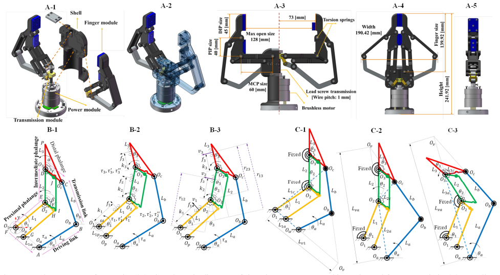
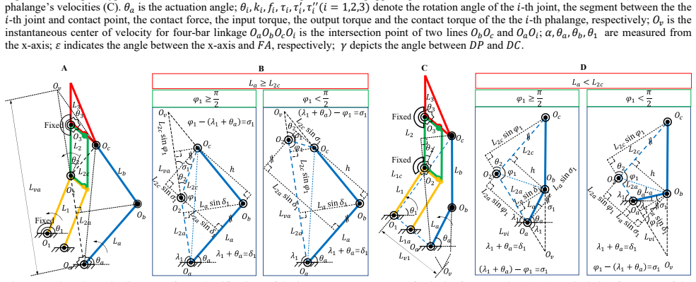
The load-bearing mechanism is a finger built as a five-linkage chain that stacks two parallelogram four-bar linkages sharing the middle phalanx; a torsional spring at one joint keeps the phalanges rigid during parallel grasps and lets them collapse sequentially during enveloping grasps. The argument then runs through three connected pieces: inverse kinematics by vector-loop equations, static equilibrium via virtual work, and a transmission matrix $\mathbf{T}$ obtained by Kennedy's theorem from the instantaneous center of velocity of the four-bar linkage. The final piece is the MS-LSTM estimator: a median-then-mean filtered current signal, a statistical model of current uncertainty, and an LSTM that outputs the grasping mode, from which the critical angle $\theta_1$ is predicted and then corrected by polynomial fitting. Equation (34) inverts the lower-triangular Jacobian $\mathbf{J}$ to convert actuator torque and spring torques into contact forces $f_1, f_2, f_3$.
What would settle it
Repeat the force-sensing experiment with an object and motor speed outside the calibration set (for instance, $\theta_1$ at 25 or 70 degrees, or speed at 40 or 90 rpm) while instrumenting each phalanx with a thin commercial force sensor, and compare the measured contact forces with those computed by Eq. (34). Exceeding the claimed average deviation of 1.71 N or the mode-switch angle error of 1.3 degrees would falsify the claimed generality.
Extended reading notes
Core claim
The paper's discovery is that force feedback in a rigid under-actuated gripper can be reconstructed from quantities already available at the motor — current, position, and velocity — instead of from tactile or force sensors. During closing grasps the actuator current has a Gaussian spread that grows with load; median and mean filtering turn this into a stable signal, and the LSTM classifies each time step as parallel-grasp or enveloping-grasp mode, predicting the critical angle $\theta_1$ at the switching instant. That predicted angle, combined with three decoupling cases for the order of phalanx contact, supplies the missing configuration to the lower-triangular Jacobian and transmission-matrix model, so Eq. (34) yields the contact forces $f_1, f_2, f_3$. The paper reports average normal-force deviation below 1.71 N, maximum deviation 6.5 N, mode-switch $\theta_1$ prediction error mostly within 0.7–0.8 degrees, normal payload over 340 N in some poses, and radial/axial payloads of 150 N and 180 N in parallel grasps, and argues this exceeds Robotiq85 in both sensing error and payload.
Load-bearing premise
The accuracy rests on the assumption that the current-to-angle mapping learned on 16 training objects, with $\theta_1$ from 30 to 60 degrees and motor speeds of 50 to 80 rpm, continues to give the correct mode-switch angle for objects, speeds, sizes, and contact orders outside that envelope; the paper demonstrates the accuracy inside the envelope and itself notes that irregular shapes such as a gamepad make sensorless force sensing difficult.
Editorial extensions
If this is right
- Force-feedback control can protect fragile or deformable objects without adding a force sensor; elastic-ring deformation tests match the set forces of 50 N, 75 N, and 100 N.
- A single actuator with a non-back-drivable screw-nut transmission maintains grasp pose and supports high payloads: over 340 N normal in some poses, 250 N radial, and 150 N radial / 180 N axial in parallel grasps.
- Automatic mode switching extends the graspable dimension range from a 1.85 mm coin to a 125 mm cube.
- The sensing pipeline, being built from current statistics plus a mechanism model, is portable in principle to other linkage-based under-actuated grippers that lack force sensors.
- The reported force-sensing error below 3% and the payload advantage position GL-Robot as a low-cost alternative to Robotiq85 in industrial settings.
Reading between the lines
- Inference beyond the paper: the three contact-order categories (distal-first, middle-first, proximal-first) imply that objects whose contact sequence falls outside these categories are exactly where Eq. (34) lacks a valid decoupled input, which matches the paper's admitted difficulty with shapes such as a gamepad.
- Inference beyond the paper: because the polynomial correction surface absorbs screw gaps, shaft-pin fit errors, and encoder resolution into one fitted surface, the same sensing pipeline could be calibrated per production unit rather than per design, making the claimed low-cost commercialization more robust.
- Inference beyond the paper: training the mode classifier in simulation with randomized object geometry, contact order, and speed coverage could supply the wide data distribution the current 16-object, 50–80 rpm training set lacks; the testable prediction is whether the 1.6% error rate survives that domain shift.
Editorial analysis
A structured set of objections, weighed in public.
Referee Report
Summary. This paper reports the design and evaluation of GL-Robot, a two-finger, three-phalanx under-actuated gripper driven by a single motor. The finger mechanism uses stacked four-bar linkages to switch between parallel and enveloping grasp modes. The authors derive inverse kinematics and a static-equilibrium model that maps actuator current and joint angles to per-phalanx contact forces, with the angle needed for the mode transition supplied by a filtered-current statistical analysis and an LSTM classifier whose output is compensated by polynomial fitting. Experiments report force-sensing accuracy with average deviation below 1.71 N and an average deviation rate of 1.6%, payloads up to 340 N in some configurations, and radial/axial loads well above those of Robotiq85. The paper claims that this constitutes force-feedback control without any force sensor.
Significance. The mechanism-level results—high payload, form-closure with three phalanges, wide dimensional range, and the parallel/enveloping transition—are concrete and are supported by the reported experiments and the standard kinematic analysis. If the force-sensing pipeline worked for arbitrary objects, it would be a significant step toward low-cost sensorless force control. The work also offers a useful combination of model-based static equilibrium and learned mode classification. However, the headline accuracy claim is validated only under conditions where the contact locations are known in advance and where the learning pipeline operates inside its training envelope; the paper itself concedes that force sensing on irregular objects remains difficult. The central novelty therefore requires substantial additional evidence or a narrower statement of scope.
major comments (3)
- [II.C, Eq. (34); IV-A-1a] The contact force vector is computed via f = J^{-T} T^T t, and the Jacobian entries in Eq. (19) depend on k_i, the distances from the joints to the contact points. The manuscript provides no sensor or estimator for these k_i for a general object. In the normal-force validation the force sensor is deliberately mounted so its center is at the distal-phalanx midpoint, k_3 = L_3/2, and in the multi-point enveloping tests on a cylinder the contact locations are geometrically fixed. The reported average deviation of 1.71 N and 1.6% rate therefore holds only when the contact positions are supplied externally. Because a single distal contact gives f_3 = tau'_3 / k_3, a 20% error in k_3 causes roughly a 20% error in the estimated force, an order of magnitude above the claimed error rate. The gamepad caveat in Sec. IV-C is a direct consequence of this missing contact-position observability rather than an isolated irregular-object case.
- [III.C; IV-A] The LSTM is trained on 16 objects spanning theta_1 in [30 deg, 60 deg] at motor speeds 50-80 rpm, using the actual theta_1 value as the supervisory label, and the force-sensing experiments are conducted within the same envelope. This makes the reported angle and force accuracy an interpolation result. No held-out objects, speeds, angles, or cross-validation are reported, so the load-bearing assumption that the current-to-configuration mapping generalizes is unproven. Either add out-of-envelope validation or explicitly restrict the force-sensing claim to the calibrated envelope.
- [II.C, contact-order decoupling] The three decoupling cases are introduced heuristically, with the statement 'After conducting a large number of grasping experiments...' providing the justification, but no quantitative criterion is given for detecting which phalanx makes first contact. The LSTM output is binary, '0' for parallel and '1' for enveloping, so it cannot select among the three cases. Case (3) requires a mapping in which theta_2 and theta_3 move while theta_1 is unchanged, yet that mapping is not written down. Since Eq. (34) needs both the correct joint angles and the correct set of active contacts, an incorrect decoupling case produces forces from the wrong Jacobian. The taxonomy should be formalized and validated against directly measured joint angles.
minor comments (5)
- [II.B, Eq. (10)] The third line of Eq. (10) defines rho_2 again; based on the derivation it should define rho_3.
- [II.C, Eq. (14)] The indexing 'n(n=1)' is inconsistent because the vectors below have three entries; the range of n and the placement of the torsional springs should be restated without this typo.
- [Fig. 8 and III.C] The text says the data are fitted 'using quadratic polynomials and quartic polynomials, respectively,' but it is unclear which polynomial is applied to the speed axis and which to the object-size axis; label the fits in the figure and caption.
- [Table IX and IV.C] The comparison with Robotiq85 should cite the published specification source and report the test conditions or uncertainty for the Robotiq85 numbers, since the five-times and seven-times comparisons are central to the commercialization claim.
- [Abstract and II.A] Terminology for the finger linkage is inconsistent: the abstract calls it a 'five-linkage mechanism stacked by double four-linkages' while Section II.A calls it a 'six-bar mechanism'; use one name and show the bar count in the schematic.
Circularity Check
No significant circularity: the force-sensing claim is a calibrated estimator built from the mechanism model and supervised current-to-angle mapping, with force accuracy checked against an independent force sensor.
full rationale
Eq. (34) is obtained from the virtual-work relation t^T omega_a = F^T v = tau^T theta_dot, with the Jacobian (19) and transmission matrix (22)-(31) derived from geometry and Kennedy's theorem. No force data are used to fit these equations, so the force model is not an output of the experiments. The remaining inputs are tau_a = A I and the phalanx angles. Theta1 is obtained from a supervised LSTM classifier and polynomial compensator whose training labels are the actual theta1; this makes the reported theta1 accuracy an interpolation result within the 30-60 deg / 50-80 rpm envelope, but it is a calibration step that is explicitly disclosed, not a hidden assumption of the conclusion. Force-sensing validation uses an external force sensor at a deliberately known contact point k3=L3/2; this supplies a quantity the model requires but does not estimate. That limits the claim for arbitrary objects and is acknowledged in Sec. IV-C as a 'quite difficult challenge' for irregular-shaped objects, but it is a correctness/generalizability caveat, not circular reasoning. The self-citations [3], [14], and [15] are contextual and not load-bearing for the derivation. Therefore no step reduces to its own input by construction.
Assumptions & free parameters
free parameters (3)
- LSTM network weights and hyperparameters =
Not disclosed; trained on 1,600 labeled current-angle samples
- Polynomial compensation coefficients for theta_1 deviation =
Quadratic in motor speed, quartic in object size (Fig. 8)
- Current filter parameters and mode-switch threshold =
Not specified; two-stage median and mean filters used
assumptions (5)
- domain assumption Static equilibrium: input virtual power equals output virtual power (Eq. 13), with frictionless contacts.
- ad hoc to paper The three-joint motion can be decoupled into three contact-order cases so accurate mapping relationships between the actuation angle and joint angles exist.
- domain assumption Motor current is approximately Gaussian about its setpoint and its standard deviation increases with load, enabling mode-switch detection from current fluctuations.
- standard math Kennedy's theorem and four-bar instantaneous centers correctly determine the transmission matrix T.
- ad hoc to paper When the Jacobian is singular due to fewer than three contacts, deleting the row and column of the non-contacting phalanx preserves the correct force balance.
Cite this review
Pith. "Pith review of Construction of a Multiple-DOF Under-actuated Gripper with Force-Sensing via Deep Learning." pith.science (2026). https://pith.science/paper/SOZBEI3D
@misc{pith2026250611570,
  author       = {Pith},
  title        = {Pith review of: Construction of a Multiple-DOF Under-actuated Gripper with Force-Sensing via Deep Learning},
  year         = {2026},
  howpublished = {\url{https://pith.science/paper/SOZBEI3D}},
  note         = {Machine review of arXiv:2506.11570}
}
read the original abstract
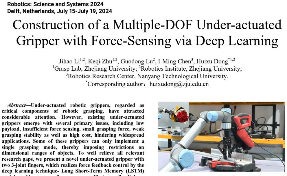
We present a novel under-actuated gripper with two 3-joint fingers, which realizes force feedback control by the deep learning technique- Long Short-Term Memory (LSTM) model, without any force sensor. First, a five-linkage mechanism stacked by double four-linkages is designed as a finger to automatically achieve the transformation between parallel and enveloping grasping modes. This enables the creation of a low-cost under-actuated gripper comprising a single actuator and two 3-phalange fingers. Second, we devise theoretical models of kinematics and power transmission based on the proposed gripper, accurately obtaining fingertip positions and contact forces. Through coupling and decoupling of five-linkage mechanisms, the proposed gripper offers the expected capabilities of grasping payload/force/stability and objects with large dimension ranges. Third, to realize the force control, an LSTM model is proposed to determine the grasping mode for synthesizing force-feedback control policies that exploit contact sensing after outlining the uncertainty of currents using a statistical method. Finally, a series of experiments are implemented to measure quantitative indicators, such as the payload, grasping force, force sensing, grasping stability and the dimension ranges of objects to be grasped. Additionally, the grasping performance of the proposed gripper is verified experimentally to guarantee the high versatility and robustness of the proposed gripper.
Figures

Figures from the paper (14 more)




Reference graph
Works this paper leans on
-
[1]
The maximum grasping force can be in general Figure
Grasping force We conducted experiments on the grasping forces to verify the precision of force sensing by the proposed MS- LSTM model and the corresponding payload capacity of GL- Robot. The maximum grasping force can be in general Figure. 11. Deviation distributions of testing the normal fo rces applied by the gripper with the first joint angle 40°, 50°...
-
[2]
Grasping with the force-feedback control We conduct experiments by comparing deformations of an elastic ring after being forced from a dynamometer, intuitively verifying the effectiveness of the proposed force- sensing method in practical force-feedback control applications (see Fig.14). The relationship between the force applied to the elastic and the de...
-
[3]
Dimension ranges of objects to be grasped To achieve the dimension ranges of objects to be grasped, we carry out tests of GL-Robot to grasp objects with various dimensions. GL-Robot can grasp a coin with a thickness of 1.85mm in the parallel grasping mode and a cubic object with a length of 125mm in the enveloping grasping mode. Therefore, GL-Robot can ha...
-
[4]
H. Dong, E. Asadi, G. Sun, D. K. Prasad, and I.-M. Chen, "Real- time robotic manipulation of cylindrical objects in dynamic scenarios through elliptic shape primitives," IEEE Transactions on Robotics, vol. 35, no. 1, pp. 95-113, 2018
work page 2018
-
[5]
Object Pose Estimation via Pruned Hough Forest With Combined Split Schemes for Robotic Grasp,
H. Dong, D. K. Prasad, and I.-M. Chen, "Object Pose Estimation via Pruned Hough Forest With Combined Split Schemes for Robotic Grasp," IEEE Transactions on Automation Science and Engineering, 2020
work page 2020
-
[6]
Geometric design optimization of an under- actuated tendon-driven robotic gripper,
H. Dong, E. Asadi, C. Qiu, J. Dai, and I.-M. Chen, "Geometric design optimization of an under- actuated tendon-driven robotic gripper," Robotics and Computer-Integrated Manufacturing , vol. 50, pp. 80-89, 2018
work page 2018
-
[7]
The Velo gripper: A versatile single-actuator design for enveloping, paralle l and fingertip grasps,
M. Ciocarlie et al., "The Velo gripper: A versatile single-actuator design for enveloping, paralle l and fingertip grasps," The International Journal of Robotics Research , vol. 33, no. 5, pp. 753-767, 2014
work page 2014
-
[8]
Underactuated adaptive gripper using flexural buckling,
G.-P. Jung, J.-S. Koh, and K.-J. Cho, "Underactuated adaptive gripper using flexural buckling," IEEE Transactions on Robotics, vol. 29, no. 6, pp. 1396-1407, 2013
work page 2013
Show all 25 references
-
[9]
Design and Implementation of a Multi-Function Gripper for Grasping General Objects,
L. Kang, J.-T. Seo, S.-H. Kim, W.-J. Kim, and B.-J. Yi, "Design and Implementation of a Multi-Function Gripper for Grasping General Objects," Applied Sciences, vol. 9, no. 24, p. 5266, 2019
2019
-
[10]
Analysis of fingertip force vector for pinch-lifting gripper with robust adaptation to environments,
D. Yoon and Y. Choi, "Analysis of fingertip force vector for pinch-lifting gripper with robust adaptation to environments," IEEE Transactions on Robotics , vol. 37, no. 4, pp. 1127-1143, 2021
2021
-
[11]
Actuation system for highly underactuated gripping mechanism,
T. Laliberté and C. Gosselin, "Actuation system for highly underactuated gripping mechanism," ed: Google Patents, 2003
2003
-
[12]
Underactuated mechanical finger with return actuation,
C. M. Gosselin and T. Lalib erte, "Underactuated mechanical finger with return actuation," ed: Google Patents, 1998
1998
-
[13]
Discrete Cosserat approach for soft robot dynamics: A new piece-wise constant strain model with torsion and shears,
F. Renda, V. Cacucciolo, J. Di as, and L. Seneviratne, "Discrete Cosserat approach for soft robot dynamics: A new piece-wise constant strain model with torsion and shears," in 2016 IEEE/RSJ International Confer ence on Intelligent Robots and Systems (IROS), 2016, pp. 5495-5502: IEEE
2016
-
[14]
A Compliant Adaptive Gripper and Its Intrinsic Force Sensing Method,
W. Xu, H. Zhang, H. Yuan, and B. Liang, "A Compliant Adaptive Gripper and Its Intrinsic Force Sensing Method," IEEE Transactions on Robotics, 2021
2021
-
[15]
Gelsight fin ray: Incorporating tactile sensing into a soft co mpliant robotic gripper,
S. Q. Liu and E. H. Adelson, "Gelsight fin ray: Incorporating tactile sensing into a soft co mpliant robotic gripper," in 2022 IEEE 5th International Conference on Soft Robotics (RoboSoft) , 2022, pp. 925-931: IEEE
2022
-
[16]
A compliant adaptive gripper and its intrinsic force sensing method,
W. Xu, H. Zhang, H. Yuan, and B. Liang, "A compliant adaptive gripper and its intrinsic force sensing method," IEEE Transactions on Robotics, vol. 37, no. 5, pp. 1584-1603, 2021
2021
-
[17]
Construction of interaction parallel manipulator: towards rehabilitation massage,
H. Dong, Y. Feng, C. Qiu, and I.-M. Chen, "Construction of interaction parallel manipulator: towards rehabilitation massage," IEEE/ASME Transactions on Mechatronics , vol. 28, no. 1, pp. 372-384, 2022
2022
-
[18]
Gsg: A granary-shaped soft gripper with mechanical sensing via snap- through structure,
H. Dong, C.-Y. Chen, C. Qiu, C.-H. Yeow, and H. Yu, "Gsg: A granary-shaped soft gripper with mechanical sensing via snap- through structure," IEEE Robotics and Automation Letters , vol. 7, no. 4, pp. 9421-9428, 2022
2022
-
[19]
Force control of a 3D printed soft gripper with bu ilt-in pneumatic touch sensing chambers,
C. Tawk, E. Sariyildiz, and G. Alici, "Force control of a 3D printed soft gripper with bu ilt-in pneumatic touch sensing chambers," Soft Robotics, vol. 9, no. 5, pp. 970-980, 2022
2022
-
[20]
Push-on push-off: A compliant bistable gr ipper with mechanical sensing and actuation,
J. McWilliams, Y. Yuan, J. Friedman, and C. Sung, "Push-on push-off: A compliant bistable gr ipper with mechanical sensing and actuation," in 2021 IEEE 4th International Conference on Soft Robotics (RoboSoft), 2021, pp. 622-629: IEEE
2021
-
[21]
A bistable soft gri pper with mechanically embedded sensing and actuation for fast grasping,
T. G. Thuruthel, S. H. Abidi, M. Cianchetti, C. Laschi, and E. Falotico, "A bistable soft gri pper with mechanically embedded sensing and actuation for fast grasping," in 2020 29th IEEE International Conference on Robot and Human Interactive Communication (RO-MAN), 2020, pp. 1...
2020
-
[22]
H ybrid motion/force control of multi- backbone continuum robots,
A. Bajo and N. Simaan, "H ybrid motion/force control of multi- backbone continuum robots," The International journal of robotics research, vol. 35, no. 4, pp. 422-434, 2016
2016
-
[23]
Shape-reconstruction-based force sensing method for continuum surgical robots with large deformation,
H. Yuan, P. W. Y. Chiu, a nd Z. Li, "Shape-reconstruction-based force sensing method for continuum surgical robots with large deformation," IEEE Robotics and Automation Letters , vol. 2, no. 4, pp. 1972-1979, 2017
1972
-
[24]
J. M. McCarthy and G. S. Soh, Geometric design of linkages . Springer Science & Business Media, 2010
2010
-
[25]
Kinetostatic analysis of underactuated fingers,
L. Birglen and C. M. Gosse lin, "Kinetostatic analysis of underactuated fingers," IEEE Transactions on Robotics and Automation, vol. 20, no. 2, pp. 211-221, 2004
2004
Reviewed August 7, 2026 · model on record in the stance chip above.
Discussion (0). Continue with ORCID to comment.