REVIEW 5 major objections 5 minor 15 references
Torsional Behavior of Carbon-Doped Ferrous Nanowires: Atomic-Scale Insights from MD Simulations
T0 review · 5 major / 5 minor · reviewed 2026-08-06 · deepseek-v4-flash
Pith's one-line read Carbon doping weakens iron nanowires under torsion, simulations show.
desk verdict First systematic MD map of Fe-C nanowire torsion, with a credible setup and expected trends, but the shear-stress metric is underdefined and the quantitative claims are not reproducible as written. read the letter →
The pith
A machine-rendered reading of the paper's core claim, the machinery that carries it, and where it could break.
The reading
What carries the argument
The central object is a set of circular BCC Fe and Fe-C nanowires with [001] orientation, twisted in LAMMPS with the Liyanage MEAM potential. The loading procedure rotates the two end blocks in opposite directions at 2e11 degrees per second in 1-degree steps with a 20 ps relaxation between steps; the response is tracked as shear stress versus torsional angle, with the critical angle defined as the point of maximum shear stress before plastic flow. Dislocation evolution is identified with Common Neighbor Analysis in OVITO. The MEAM potential is the load-bearing element: the claim that carbon weakens torsion rests entirely on how this potential describes Fe-C interactions under large strain.
What would settle it
Repeat the 1 K, 10%-carbon torsion runs with a different interatomic potential validated against high-strain Fe-C data (for example, one fitted to DFT shear and fracture energies) and with several independent random carbon distributions; if the maximum shear stress and critical angle do not decrease monotonically with carbon content, or if the 10% instability disappears, the claimed carbon-weakening trend is an artifact of the chosen potential rather than a property of Fe-C nanowires.
Extended reading notes
Core claim
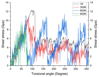
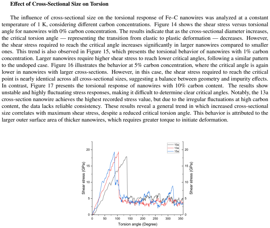
The central claim is that carbon concentration, temperature, and cross-sectional diameter each move the shear stress versus rotation-angle curve of [001] Fe nanowires in a specific direction. Increasing carbon from 0% to 10% reduces the maximum shear stress and the critical torsional angle, and makes the elastic-plastic transition indistinct above 5%. Increasing temperature from 1 K to 900 K also lowers strength and critical angle. Increasing diameter from 10a to 15a raises the shear stress needed to reach the critical angle while reducing that angle. The paper attributes these trends to carbon-induced lattice distortion acting as stress concentrators, thermal vibration enhancing atomic mobility and dislocation nucleation, and the larger strained outer surface of thicker wires.
Load-bearing premise
The entire trend depends on the Liyanage MEAM potential being accurate for Fe-C interactions under torsional loading up to 10% carbon and through plastic failure, even though it was fitted to structural, elastic, and thermal properties, not to torsion or fracture.
Editorial extensions
If this is right
- Fe-C nanowires intended for torsional components in NEMS or actuators should avoid carbon concentrations above 5% if a clean elastic-plastic transition is needed.
- At high temperature and high carbon content, the critical torsional angle ceases to be a well-defined design parameter because the stress-angle curves become highly unstable.
- Larger cross-sectional nanowires tolerate higher shear stress but reach their critical angle earlier, so size alone does not extend the usable elastic rotation range.
- The same MEAM potential can be used to predict torsional strength of other Fe-C nanostructures, extending the earlier tensile-loading application of this potential.
Reading between the lines
- Because the study uses a single random carbon distribution per concentration, the reported instability at 10% carbon could be sensitive to the specific placement of interstitial atoms; repeating with multiple random seeds or ordered carbon arrangements would test whether the trend is robust.
- The weakening with carbon opposes the classical solid-solution strengthening seen in bulk steels, suggesting a possible size-dependent crossover: at the nanoscale, carbon-induced dislocation nucleation may dominate over dislocation pinning, which would have implications for miniaturized steel components.
- The 20 ps relaxation after each 1-degree rotation acts as an effectively slower loading rate; varying this relaxation time could reveal whether the critical angles and stress values are rate-dependent, a natural next step given that the paper notes torsion rate effects in prior copper nanowire studies.
Signed reviews
Editorial analysis
A structured set of objections, weighed in public.
Referee Report
Summary. The paper reports molecular dynamics simulations of torsional loading of [001]-oriented body-centered cubic iron and carbon-doped iron nanowires using the MEAM potential of Liyanage et al. The parameter sweep is over carbon concentration (0, 1, 5, 10%), temperature (nominally 1 K or 0 K to 900 K), and cross-sectional size (10a, 13a, 15a). The central claims are that increasing carbon concentration lowers the maximum shear stress and the critical torsional angle, that increasing temperature reduces torsional strength, and that larger cross-sections increase the shear stress required for deformation. The paper presents shear stress versus torsional angle curves, critical-angle values, and dislocation/strain visualizations from OVITO.
Significance. If the reported trends are quantitatively reproducible, the paper would provide a useful first mapping of carbon-doping, temperature, and size effects on the torsional response of Fe-C nanowires, with potential relevance to NEMS design. The work has strengths: it uses a previously published MEAM potential fitted to independent structural, elastic, and thermal data; it covers a systematic parameter matrix; and it includes atomic-scale visualization of dislocation and strain patterns. However, the quantitative content is currently not reproducible because the shear-stress observable is not defined, the curves come from single unseeded realizations without error bars, and the temperature labels are inconsistent. The qualitative directions of the trends may be correct, but the evidence as presented is insufficient to distinguish them from sampling noise or from artifacts of an ill-defined stress metric.
major comments (5)
- [Methodology, shear-stress calculation] The shear-stress metric used in Figures 3-17 is not defined. The text states only that it is "the sum of the per-atom stress components calculated by the Virial expression implemented in LAMMPS"; it does not state which tensor component is used (e.g., xy, the longitudinal shear components, von Mises, or the trace), how the per-atom values are aggregated, or whether the result is volume-normalized. LAMMPS per-atom virial stress has units of energy (or pressure-volume depending on output) and contains a kinetic term, so different choices change both the absolute magnitudes and the relative ordering of the curves. Since maximum shear stress is the basis for the critical-angle definition and for the carbon-weakening conclusion, the central quantitative claims cannot be tested until this quantity is specified and, ideally, validated against a torque-based shear-stress definition.
- [Methodology, simulation protocol and Figures 3-17] Each reported curve appears to come from a single unseeded MD run. Carbon atoms are said to be randomly distributed, but no random seed or ensemble of independent configurations is described, and no error bars or convergence tests are reported. Given the large fluctuations in the 10% carbon and high-temperature curves, the observed differences between concentrations and sizes could reflect sampling noise rather than systematic trends. Please provide multiple independent realizations per condition and report the mean and spread (or at least a convergence check for the key 0% versus 10% comparison at the low-temperature baseline).
- [Effect of Temperature on Torsion] The temperature axis is internally inconsistent. The abstract and Methodology state 1 K; the Effect of Temperature section states "Simulations were conducted at 0 K, 300 K, 600 K, and 900 K"; the figure captions and text report values at 1 K; and Figure 13 is described at 0 K. This must be reconciled because the low-temperature baseline anchors the temperature trend. If the simulations are at 1 K, relabel all text and figures; if some are at 0 K, the data and thermostat settings need to be clarified.
- [Methodology, critical torsional angle definition] The critical angle is defined as "the point at which maximum shear stress is reached before plastic deformation begins," but no operational rule is given for curves that have no clear maximum, as admitted for 10% carbon and high temperatures. Without an automated or at least reproducible peak/no-peak criterion, the reported critical-angle values (e.g., 137°, 140°, 100°, 114°) cannot be independently extracted from the raw curves. Please define the algorithm used to assign critical angles or state explicitly which curves were excluded from this determination.
- [Methodology, MEAM potential choice] The central results rely on extrapolating the Liyanage et al. MEAM potential to high carbon concentrations (10%) and to plastic failure under torsion, neither of which is part of the potential's fitted property set (structural, elastic, and thermal properties of BCC Fe and Fe-C phases). This is a correctness-risk concern, not a circularity claim. A concrete check would be to compare one representative stress-angle curve (e.g., 0% carbon, 10a, 1 K) against an alternative Fe potential or, if available, against experimental or DFT data on Fe shear behavior; at minimum, state the expected validity range of the potential for torsion and failure.
minor comments (5)
- [Abstract] The abstract states that "increasing carbon content weakens grain boundaries," but the simulated nanowires are single-crystal BCC without grain boundaries; the observed weakening is attributed to interstitial lattice distortion and should be reworded to avoid implying a grain-boundary mechanism.
- [Header] The preprint header says "Preprint submitted to Computational Material Scinece"; this should read "Computational Materials Science."
- [Methodology and Figure 6 caption] The cross-sectional size is described as "diameter" in the Methodology but as "radius" in the text and in the Figure 6 caption; the terminology should be made consistent throughout.
- [Effect of Temperature on Torsion] The section discusses potential-energy fluctuations and Figures 7 and 8 appear in that section, but the text never explicitly refers to those figures; please add the citations or remove the figures.
- [General] There are numerous grammar and spacing errors (e.g., "Figure 6, further illustrates," "di fferent," "Y , Z"); a careful proofreading pass is needed.
Circularity Check
No circular derivation: the torsion trends are MD outputs, not inputs; only a minor non-load-bearing self-citation lowers the score.
full rationale
The paper reports molecular dynamics simulation outcomes for Fe and Fe–C nanowires under torsion, and none of the claimed trends (carbon weakens torsional capacity, temperature lowers strength, larger cross-sections increase shear stress) is imposed by construction. The paper introduces no fitted parameter in this work that is later renamed as a prediction; the interatomic potential from Liyanage et al. [12] is a self-citation by the corresponding author, but that potential was fitted to structural, elastic, and thermal properties of BCC Fe and Fe–C phases, not to torsion, so the torsional response is not an input to the fit. The second same-group citation [3] is used only to state prior usage of the potential and does not carry any load in the derivation. The definitions of shear stress and critical torsional angle are operational and somewhat under-specified, but they do not encode carbon concentration, temperature, or cross-sectional size, so the reported trends are not true by definition. No equation in the manuscript reduces a claimed result to an input, and no uniqueness theorem or ansatz is imported through citation to forbid alternative outcomes. The genuine concerns—MEAM potential transferability to plastic torsion and the incomplete definition of the virial-based shear stress metric—are correctness and reproducibility risks, not circularity.
Assumptions & free parameters
free parameters (2)
- MEAM Fe-C potential parameters =
not tabulated here; from Ref. [12]
- Random carbon distribution seed =
not reported
assumptions (4)
- domain assumption The initial nanowire is a perfect BCC Fe lattice with C atoms in interstitial sites.
- domain assumption The MEAM potential transfers to high-strain torsion and 10 percent carbon.
- domain assumption NVT thermostat with stepwise 1-degree rotations and 20 ps relaxation represents quasi-static torsion.
- domain assumption The sum of per-atom virial stresses equals the torsional shear stress.
Cite this review
Pith. "Pith review of Torsional Behavior of Carbon-Doped Ferrous Nanowires: Atomic-Scale Insights from MD Simulations." pith.science (2026). https://pith.science/paper/BCAULVVL
@misc{pith2026250704901,
  author       = {Pith},
  title        = {Pith review of: Torsional Behavior of Carbon-Doped Ferrous Nanowires: Atomic-Scale Insights from MD Simulations},
  year         = {2026},
  howpublished = {\url{https://pith.science/paper/BCAULVVL}},
  note         = {Machine review of arXiv:2507.04901}
}
read the original abstract
This study investigates the torsional mechanical properties of pristine iron (Fe) and carbon-doped iron (FeC) nanowires with [001] orientation through molecular dynamics simulations utilizing the Modified Embedded Atom Method (MEAM) potential developed by Liyanage et al. for accurately modeling Fe-C interactions in body-centered cubic structures. Systematic analysis across carbon concentrations (0 - 10%), temperatures (1 - 900 K), and cross-sectional dimensions 10a, 13a, 15a, ( where a = 2.81 Angstrom represents the lattice constant ) within the LAMMPS environment reveals that increasing carbon content weakens grain boundaries, reducing the maximum shear stress required to reach the critical torsional angle, while higher temperatures promote phase transitions from elastic to plastic deformation due to enhanced atomic vibrations, and larger cross-sections exhibit higher shear stress resistance attributed to strengthening effects from the outer atomic layers. By elucidating these interrelationships between carbon content, temperature, and dimensional factors, this work provides fundamental insights into the mechanical behavior of FeC nanowires under torsional loading conditions, offering valuable guidance for their potential applications in nanoelectromechanical systems, nanorobotic actuators, and advanced structural materials where precise control of mechanical properties is essential.
Figures


Figures from the paper (15 more)






Reference graph
Works this paper leans on
- [1]
- [2]
-
[3]
T. Nadeesha, J. Liyanage, L. S. Liyanage, Prediction of mechanical properties of steel nanowires using molecular dynamics (2021)
work page 2021
-
[4]
G. Sainath, B. Choudhary, Atomistic simulations on ductile-brittle transition in¡ 111¿ bcc fe nanowires, Journal of Applied Physics 122 (9) (2017)
work page 2017
-
[5]
Z. Yang, M. Li, Y . Li, Y . Yang, J. Zhao, Molecular dynamics simulation on torsion deformation of copper aluminum core–shell nanowires, Journal of Nanoparticle Research 23 (2021) 1–10
work page 2021
-
[6]
Z. Yang, M. Li, Y . Li, Y . Yang, X. Ding, Comparisons in mechanical properties of various copper nanowires under torsion: molecular dynamics simulation, Journal of Nanoparticle Research 24 (2) (2022) 42
work page 2022
-
[7]
Y . Yang, Y . Li, Z. Yang, G. Zhang, X. Wang, J. Liu, Molecular dynamics simulation on the elastoplastic properties of copper nanowire under torsion, Journal of Nanoparticle Research 20 (2018) 1–10
work page 2018
-
[8]
Y . Gao, F. Wang, T. Zhu, J. Zhao, Investigation on the mechanical behaviors of copper nanowires under torsion, Computational Materials Science 49 (4) (2010) 826–830
work page 2010
Show all 15 references
-
[9]
Sung, C.-D
P.-H. Sung, C.-D. Wu, T.-H. Fang, E ffects of temperature, loading rate and nanowire length on torsional deformation and mechanical prop- erties of aluminium nanowires investigated using molecular dynamics simulation, Journal of Physics D: Applied Physics 45 (21) (2012) 215303
2012
-
[10]
S. Li, E. K. Salje, S. Jun, X. Ding, Large recovery of six-fold twinned nanowires of α-fe, Acta Materialia 125 (2017) 296–302
2017
-
[11]
S. J. Plimpton, A. P. Thompson, Computational aspects of many-body potentials, MRS bulletin 37 (5) (2012) 513–521
2012
-
[12]
L. S. Liyanage, S.-G. Kim, J. Houze, S. Kim, M. A. Tschopp, M. I. Baskes, M. F. Horstemeyer, Structural, elastic, and thermal properties of cementite (fe 3 c) calculated using a modified embedded atom method, Physical Review B 89 (9) (2014) 094102
2014
-
[13]
HARDEN, R
C. HARDEN, R. LEHOUCQ, Convergence verification of static solvers via energy minimization in lammps, CSRI SUMMER PROCEED- INGS 2008 (2008) 199
2008
-
[14]
Miyazaki, Y
N. Miyazaki, Y . Shiozaki, Calculation of mechanical properties of solids using molecular dynamics method, JSME international journal. Ser. A, Mechanics and material engineering 39 (4) (1996) 606–612
1996
-
[15]
A. Stukowski, Visualization and analysis of atomistic simulation data with ovito–the open visualization tool, Modelling and simulation in materials science and engineering 18 (1) (2009) 015012. 13
2009
Reviewed August 6, 2026 · model on record in the stance chip above.
Discussion (0). Continue with ORCID to comment.