REVIEW 2 major objections 6 minor 19 references
Dynamic Modeling and Dimensional Optimization of Legged Mechanisms for Construction Robot
T0 review · 2 major / 6 minor · reviewed 2026-08-06 · deepseek-v4-flash
Pith's one-line read Optimizing nine geometric leg dimensions cuts peak joint torque and energy consumption by over 20%.
desk verdict A standard leg-optimization study with an internally consistent Lagrangian model, but the energy claim is undercut by a signed-power metric and the optimization is under-specified. read the letter →
The pith
A machine-rendered reading of the paper's core claim, the machinery that carries it, and where it could break.
The reading
What carries the argument
The carrier of the argument is the Lagrangian dynamic model of the leg, in which the coxa, femur, and tibia are treated as uniform rods with mass concentrated at half length ($a_i = l_i/2$). From this model the paper derives closed-form expressions for the joint torques as functions of the nine geometric variables (length, width, and height of each segment) and of the joint angles, velocities, and accelerations along a quintic-polynomial trajectory. A genetic algorithm then minimizes a weighted sum of normalized peak torque and normalized energy consumption, with penalty terms for violating constraints on the farthest foot placement distance and the bending stiffness $EI_z = E [hw^3 - (h-2t)(w-2t)^3]/12$ of the hollow rectangular cross-sections. The same dynamic model is reused after optimization to compute the predicted torques and energies that appear in the final comparison.
What would settle it
Build or measure a leg segment with the optimized dimensions in the intended material, measure its mass and moment of inertia about the joint, and compare with the uniform-rod values used in Tables 1 and 2; if the real values differ enough to recompute the torque curves and the peak torques no longer drop by at least 20% for all joints under the planned trajectory, the claim would be falsified. A simpler check is to compute the sensitivity of the predicted torques to the unspecified wall thickness $t$ in the stiffness constraint and see whether plausible values of $t$ change the optimized dimensions.
Extended reading notes
Core claim
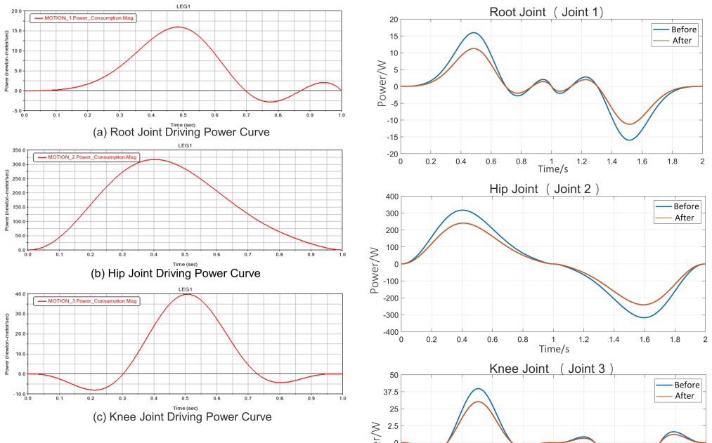
The paper's central discovery is that the geometric dimensions of a three-segment articulated leg, not just its lengths, have a strong effect on joint torque and energy consumption, and that optimizing all nine dimensions together yields a leg with substantially lower dynamic loads. Under a uniform-rod dynamic model with Lagrangian mechanics, the optimized leg reduces the peak torque of the root, hip, and knee joints by 28.53%, 24.47%, and 24.16%, respectively, and reduces energy consumption by 28.47%, 22.60%, and 24.14%. The same trend appears in the authors' multibody dynamic simulation, where joint driving power drops by roughly 20%. The optimization respects constraints on farthest foot placement distance and bending stiffness, so the lighter, shorter segments are claimed not to sacrifice the robot's reach or structural resistance.
Load-bearing premise
The entire torque and energy prediction rests on treating each leg segment as a perfectly uniform rod with mass at its midpoint and assuming the simplified hollow rectangular cross-sections preserve the real mass, center of mass, and moment of inertia, which the paper does not demonstrate.
Editorial extensions
If this is right
- If the claim holds, the same leg configuration can be used with smaller, cheaper actuators because peak torque demand drops by roughly a quarter.
- The method gives a design-time tool: from a planned trajectory, a designer can compute optimal segment dimensions for any articulated legged robot before building hardware.
- The optimization implies that leg designs which tune only segment lengths are leaving some energy savings on the table, since width and height also affect dynamic loads.
- The constraint framework for reach distance and bending stiffness provides a template for incorporating structural limits into other robot dimension optimizations.
Reading between the lines
- The paper leaves the wall thickness $t$ of the hollow cross-sections unspecified, so the mapping from the nine optimized dimensions to the reported segment masses cannot be checked from the published data alone; this is our inference from the absence of the value, not a claim the paper makes.
- The reported reductions are computed for a single two-second swing trajectory; whether the same dimensions also reduce torque and energy in stance, during walking gaits, or on uneven terrain is not tested.
- The uniform-rod model omits joint friction and air resistance, so the percentage energy savings in a physical robot could differ from the 22-28% predicted in simulation.
- The same optimization pipeline could be applied to other leg configurations and to additional objectives such as structural stress or actuator peak power, which the paper does not address.
Editorial analysis
A structured set of objections, weighed in public.
Referee Report
Summary. The paper presents a design and dimensional optimization study of a three-joint (root/hip/knee) leg for a hexapod construction robot. Joint-space trajectories are planned with quintic polynomials, a Lagrangian dynamic model is derived for three uniform-rod leg segments, and a genetic algorithm is used to optimize nine geometric variables (length, width, and height of each segment) with peak joint torque and joint energy consumption as weighted objectives, subject to foot-reach and bending-stiffness constraints. The authors report 24-28% reductions in peak torques (Table 3) and 22-28% reductions in energy consumption (Table 4), and present ADAMS simulations showing reduced joint driving power. The paper concludes that the optimized leg improves dynamic performance.
Significance. If the quantitative claims were correct, the work would offer a straightforward, reusable template for dimensioning legged-robot links: an explicit dynamic model, a transparent genetic-algorithm loop, and an independent multibody check. The dynamic equations are derived from first principles, and the trajectory polynomials are given in closed form, which are strengths. However, the energy-consumption metric in Eq. (35) is a signed sum of mechanical power and is therefore not an energy budget, and the optimization is not fully reproducible because the wall thickness in Eq. (37) and the mass/inertia formulas connecting the nine dimensions to m_i and I_i are missing. These issues bear directly on the headline 20% torque and energy reductions, so the central claim is not yet established as stated.
major comments (2)
- [V.B, Eq. (35)] Equation (35) defines Q_i as the sum of tau_i^j * thetadot_i^j * T_i^j without an absolute value, a positive-part operator, or a regenerative-loss model. For the planned trajectory, the hip velocity is nonnegative on the first swing segment (Eq. 2) and nonpositive on the second (Eq. 5), while the knee velocity has the opposite pattern (Eqs. 3 and 6); the gravitational torque components in Eqs. (30) and (33) do not share this sign symmetry. Positive and negative mechanical power intervals can therefore cancel in the sum, so Q_i is net mechanical work rather than actuator energy consumption. The 22.60-28.47% reductions in Table 4 and the abstract claim of over 20% energy reduction rest on this signed metric. The ADAMS curves in Section VI report driving power but no unsigned energy integral, so they do not repair the metric. I request recomputation with Q_i = sum |tau_i^j * thetadot_i^j| * T_i^j (or with an explicit regenerative-loss model) and rerunning the optimization under the corrected objective.
- [V.A, Eq. (37)] The wall thickness t in Eq. (37) is never defined numerically or as an optimization variable, so the bending-stiffness constraint EIz >= (1-mu)EIz0 cannot be evaluated. More generally, the paper states that the hollow rectangular simplification preserves mass, center of mass, and moment of inertia, but it provides no formulas mapping the nine design variables (l_i, w_i, h_i, and the wall thickness t) to the segment masses m_i and inertias I_i used in Eqs. (18)-(33). Tables 1 and 2 give masses for the initial and optimized designs, but the reader cannot check how m_i and I_i are updated when the dimensions change. Since every torque and energy value flows through m_i and I_i, this missing mapping is load-bearing. Please supply the closed-form mass/COM/inertia relations, the value or bounds of t, and the resulting I_i values for both designs.
minor comments (6)
- [Section III vs Table 1] The text says the trajectory plot uses initial lengths l1=200 mm, l2=400 mm, and l3=400 mm, while Table 1 lists the initial coxa length as 140 mm and the femur/tibia lengths as 460 mm; please reconcile this discrepancy or clarify that the trajectory illustration uses a different nominal set.
- [Eqs. (19)-(20)] The symbols alpha2 and alpha3 are used where a2 and a3 are intended; please standardize the notation for the center-of-mass distances.
- [Table 4] The energy values in Table 4 are labeled N-m, but Eq. (35) integrates power over time; joules (J) or N-m-s would be clearer and dimensionally correct.
- [Section V.C] The genetic-algorithm description gives only population size and iteration count; please also report crossover and mutation probabilities, selection scheme, and convergence or stall criteria so that the optimization is reproducible.
- [Section V.D] The conclusions state that energy consumption decreases by 24% to 28%, but Table 4 reports a hip-joint reduction of 22.60%; please correct this numerical inconsistency.
- [Manuscript front matter] The manuscript states twice that it is under review at Mechanics Based Design of Structures and Machines; such statements should be removed from the submitted version.
Circularity Check
No significant circularity: joint torques are derived from first principles via Lagrange's method, the reported reductions are computed optimization objectives plus an ADAMS cross-check, and the only self-citation is not load-bearing.
full rationale
I walked the derivation chain from the trajectory polynomials (Eqs. 1-6), through the Lagrangian dynamic model (Eqs. 7-33), the evaluation metrics (Eqs. 34-35), the genetic-algorithm formulation (Eqs. 36-41), and the ADAMS simulation. The joint torque equations are derived from first principles rather than fitted to the reported improvements, with the uniform-rod assumption ai = li/2 made explicit in Section IV and the hollow rectangular-section simplification stated in Section V.A. The optimization minimizes the normalized peak-torque and energy objectives in Eq. (39), so the reductions in Tables 3 and 4 are the computed outcome of that minimization, not a self-referential prediction of independent data; they are additionally checked by an ADAMS simulation, which is a consistency check using the same geometry and trajectory rather than fully independent evidence. The only apparent author self-citation, reference [14], appears in the introduction as related prior work and is not load-bearing for any conclusion. The paper's own stated limitations, including the ideal-rod assumption and the omission of friction and air resistance, are validity and reproducibility concerns rather than circularity; similarly, the absence of the wall thickness t in Eq. (37) makes the mass calculations hard to reproduce but does not make the derivation circular. The signed energy sum in Eq. (35) raises a physical-validity question about cancellation of positive and negative power, but that is a correctness issue outside the circularity definition and does not reduce the derivation to its inputs. Therefore no significant circularity is present.
Assumptions & free parameters
free parameters (3)
- Wall thickness t of hollow rectangular cross-section
- Constraint coefficients lambda and mu =
lambda = 0.05, mu = 0.15
- Objective weighting coefficients =
0.5 and 0.5
assumptions (4)
- standard math Standard Lagrange mechanics is the correct equation of motion framework
- domain assumption Each leg segment is a uniform rod with uniformly distributed mass and center of mass at half length
- domain assumption The hollow rectangular cross-section simplification preserves mass, center of mass, and moment of inertia
- domain assumption The planned joint-space trajectory is representative of real construction-robot leg motion
Cite this review
Pith. "Pith review of Dynamic Modeling and Dimensional Optimization of Legged Mechanisms for Construction Robot." pith.science (2026). https://pith.science/paper/IFJODYLL
@misc{pith2026250717132,
  author       = {Pith},
  title        = {Pith review of: Dynamic Modeling and Dimensional Optimization of Legged Mechanisms for Construction Robot},
  year         = {2026},
  howpublished = {\url{https://pith.science/paper/IFJODYLL}},
  note         = {Machine review of arXiv:2507.17132}
}
read the original abstract
With the rapid development of the construction industry, issues such as harsh working environments, high-intensity and high-risk tasks, and labor shortages have become increasingly prominent. This drives higher demands for construction robots in terms of low energy consumption, high mobility, and high load capacity. This paper focuses on the design and optimization of leg structures for construction robots, aiming to improve their dynamic performance, reduce energy consumption, and enhance load-bearing capabilities. Firstly, based on the leg configuration of ants in nature, we design a structure for the robot's leg. Secondly, we propose a novel structural optimization method. Using the Lagrangian approach, a dynamic model of the leg was established. Combining the dynamic model with the leg's motion trajectory, we formulated multiple dynamic evaluation metrics and conducted a comprehensive optimization study on the geometric parameters of each leg segment. The results show that the optimized leg structure reduces peak joint torques and energy consumption by over 20%. Finally, dynamic simulation experiments were conducted using ADAMS. The results demonstrate a significant reduction in the driving power of each joint after optimization, validating the effectiveness and rationality of the proposed strategy. This study provides a theoretical foundation and technical support for the design of heavy-load, high-performance construction robots.
Figures


Figures from the paper (8 more)


Reference graph
Works this paper leans on
-
[1]
Digital technologies in ar- chitecture, engineering, and construction,
J. Brozovsky, N. Labonnote, and O. Vigren, “Digital technologies in ar- chitecture, engineering, and construction,” Automation in Construction , 2024, 158: 105212
work page 2024
-
[2]
K. Wang, F. Guo, C. Zhang, et al., “From Industry 4.0 to Construction 4.0: Barriers to the digital transformation of engineering and construc- tion sectors,” Engineering, Construction and Architectural Management , 2022, 31(1): 136-158
work page 2022
-
[3]
Recent advancements of robotics in construction,
B. Xiao, C. Chen, and X. Yin, “Recent advancements of robotics in construction,” Automation in Construction , 2022, 144: 104591
work page 2022
-
[4]
K. D ¨orfler, G. Dielemans, L. Lachmayer, et al., “Additive Manufac- turing using mobile robots: Opportunities and challenges for building construction,” Cement and Concrete Research , 2022, 158: 106772
work page 2022
-
[5]
Optimal synthesis of walking robot leg,
S. Ibrayev, A. Ibrayeva, N. Jamalov, et al., “Optimal synthesis of walking robot leg,” Mechanics Based Design of Structures and Machines, 2024, 52(5): 2639-2659
work page 2024
-
[6]
Y . Xiao, K. Yin, X. Chen, et al., “Multi-objective optimization design method for the dimensions and control parameters of curling hexapod robot based on application performance,” Mechanism and Machine Theory, 2024, 204: 105831
work page 2024
-
[7]
Structural optimization with ex- plicit geometric constraints using a B-spline representation,
Y . M. Yoely, I. Haniel, and O. Amir, “Structural optimization with ex- plicit geometric constraints using a B-spline representation,” Mechanics Based Design of Structures and Machines , 2020: 3966-3977
work page 2020
-
[8]
Denim-fabric-polishing robot size optimization based on global spatial dexterity,
W. Wang, Q. Tao, X. Wang, et al., “Denim-fabric-polishing robot size optimization based on global spatial dexterity,” Mechanical Sciences , 2021, 12(1): 649-660
work page 2021
Show all 19 references
-
[9]
Design optimization of sandwich composite cylinder using modified differential evolution algorithm,
M. K. Bhadra and A. Jain, “Design optimization of sandwich composite cylinder using modified differential evolution algorithm,” Mechanics Based Design of Structures and Machines , 2025: 1-19
2025
-
[10]
Analysis and design optimization of a compliant robotic gripper mechanism with inverted flexure joints,
P. Kuresangsai, M. O. T. Cole, and G. Hao, “Analysis and design optimization of a compliant robotic gripper mechanism with inverted flexure joints,” Mechanism and Machine Theory , 2024, 202: 105779
2024
-
[11]
A parallel mechanism- based virtual biomechanical shoulder robot model: Mechanism design optimization and motion planning,
M. F. Shah, P. K. Jamwal, R. Goecke, et al., “A parallel mechanism- based virtual biomechanical shoulder robot model: Mechanism design optimization and motion planning,” Mechanics Based Design of Structures and Machines , 2024: 1-21
2024
-
[12]
Multi-objective optimal design of a cable driven parallel robot for rehabilitation tasks,
I.B. Hamida, M. A. Laribi, A. Mlika, et al., “Multi-objective optimal design of a cable driven parallel robot for rehabilitation tasks,” Mechanism and Machine Theory , 2021, 156: 104141
2021
-
[13]
Bio-inspired leg design for a heavy-duty hexapod robot,
H. Yi, Z. Xu, X. Xin, et al., “Bio-inspired leg design for a heavy-duty hexapod robot,” Journal of Bionic Engineering , 2022, 19(4): 975-990
2022
-
[14]
Research on structural optimization of 3- TPT parallel mechanism based on stiffness characteristics,
C. Zhu, X. Liu, and W. Liu, “Research on structural optimization of 3- TPT parallel mechanism based on stiffness characteristics,” Mechanics Based Design of Structures and Machines , 2021, 49(2): 256-270
2021
-
[15]
Design and optimization of a multimode amphibious robot with propeller-leg,
X. Ma, G. Wang, and K. Liu, “Design and optimization of a multimode amphibious robot with propeller-leg,” IEEE Transactions on Robotics , 2022, 38(6): 3807-3820
2022
-
[16]
Research on structure optimization and motion characteristics of wearable medical robotics based on improved particle swarm optimization algorithm,
Y . Zheng, Y . Wang, and J. Liu, “Research on structure optimization and motion characteristics of wearable medical robotics based on improved particle swarm optimization algorithm,” Future Generation Computer Systems, 2022, 129: 187-198
2022
-
[17]
Performance based design optimization of an intrinsically compliant 6-dof parallel robot,
P. K. Jamwal, A. Kapsalyamov, S. Hussain, et al., “Performance based design optimization of an intrinsically compliant 6-dof parallel robot,” Mechanics Based Design of Structures and Machines , 2022, 50(4): 1237-1252
2022
-
[18]
Optimal design and implementation of an amphibious bionic legged robot,
G. Wang, K. Liu, X. Ma, et al., “Optimal design and implementation of an amphibious bionic legged robot,” Ocean Engineering , 2023, 272: 113823
2023
-
[19]
Design and optimization of a deep- sea multimode crawling–swimming hexapod robot with leg-propeller,
L. Ding, L. Hu, Y . Liu, et al., “Design and optimization of a deep- sea multimode crawling–swimming hexapod robot with leg-propeller,” Ocean Engineering , 2023, 280: 114485
2023
Reviewed August 6, 2026 · model on record in the stance chip above.
Discussion (0). Continue with ORCID to comment.