Learning Hierarchical and Geometry-Aware Graph Representations for Text-to-CAD
Pith reviewed 2026-05-10 16:14 UTC · model grok-4.3
The pith
Predicting a hierarchical graph with geometric constraints first improves text-to-CAD code generation by reducing errors in complex assemblies.
A machine-rendered reading of the paper's core claim, the machinery that carries it, and where it could break.
Core claim
The central claim is that a hierarchical and geometry-aware graph serves as an effective intermediate representation for text-to-CAD translation: nodes represent multi-level parts and components while edges encode explicit geometric constraints, allowing the model to predict structure and constraints from text before conditioning code generation on them, which improves geometric fidelity and constraint satisfaction over direct decoding approaches.
What carries the argument
The hierarchical and geometry-aware graph, with multi-level parts as nodes and geometric constraints as edges, which acts as the bridge that narrows the search space and conditions subsequent code generation.
Load-bearing premise
That the graph structure and constraints can be accurately predicted from text and that this intermediate form captures the dependencies needed to prevent errors from cascading in the final code.
What would settle it
If a baseline that decodes text directly to code matches or exceeds the proposed method on geometric fidelity and constraint satisfaction metrics when both are trained and tested on the same 12K dataset, the value of the graph intermediate would be refuted.
Figures


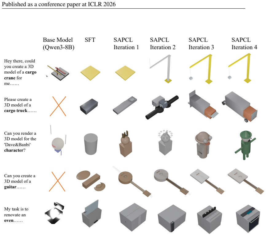


read the original abstract
Text-to-CAD code generation is a long-horizon task that translates textual instructions into long sequences of interdependent operations. Existing methods typically decode text directly into executable code (e.g., bpy) without explicitly modeling assembly hierarchy or geometric constraints, which enlarges the search space, accumulates local errors, and often causes cascading failures in complex assemblies. To address this issue, we propose a hierarchical and geometry-aware graph as an intermediate representation. The graph models multi-level parts and components as nodes and encodes explicit geometric constraints as edges. Instead of mapping text directly to code, our framework first predicts structure and constraints, then conditions action sequencing and code generation, thereby improving geometric fidelity and constraint satisfaction. We further introduce a structure-aware progressive curriculum learning strategy that constructs graded tasks through controlled structural edits, explores the model's capability boundary, and synthesizes boundary examples for iterative training. In addition, we build a 12K dataset with instructions, decomposition graphs, action sequences, and bpy code, together with graph- and constraint-oriented evaluation metrics. Extensive experiments show that our method consistently outperforms existing approaches in both geometric fidelity and accurate satisfaction of geometric constraints.
Editorial analysis
A structured set of objections, weighed in public.
Referee Report
Summary. The paper claims that direct text-to-CAD code generation (e.g., bpy sequences) enlarges the search space and causes cascading errors in complex assemblies because it fails to model hierarchy or geometric constraints explicitly. It proposes a hierarchical geometry-aware graph as an intermediate representation (nodes as multi-level parts/components, edges as explicit geometric constraints), with a two-stage process that first predicts the graph from text and then conditions action sequencing and code generation on it. A structure-aware progressive curriculum learning strategy is introduced to synthesize graded tasks via controlled edits, along with a new 12K dataset containing instructions, decomposition graphs, action sequences, and bpy code, plus graph- and constraint-oriented metrics. Experiments reportedly show consistent outperformance over baselines in geometric fidelity and constraint satisfaction.
Significance. If the central claims hold, the work offers a structured way to mitigate error accumulation in long-horizon text-to-code tasks for CAD, which has practical value for automated design and manufacturing. The explicit introduction of a 12K dataset with hierarchical annotations and the curriculum strategy are concrete contributions that could support future research on intermediate representations for structured generation. The geometry-aware graph formulation directly targets a known weakness in prior direct-decoding approaches.
major comments (1)
- Abstract and Experiments section: The central claim that the hierarchical graph 'improves geometric fidelity and constraint satisfaction' by avoiding cascading failures is load-bearing, yet no per-stage accuracy for graph prediction (hierarchy or constraint edges) or oracle-graph ablation is reported. Without these, it is impossible to determine whether the intermediate representation reduces error sources or merely relocates them into the graph predictor, undermining the argument that the two-stage approach is superior to direct decoding.
Simulated Author's Rebuttal
We thank the referee for the constructive feedback and for recognizing the potential value of the hierarchical geometry-aware graph and the new dataset. We address the major comment below and will revise the manuscript accordingly to strengthen the evaluation of the two-stage approach.
read point-by-point responses
-
Referee: Abstract and Experiments section: The central claim that the hierarchical graph 'improves geometric fidelity and constraint satisfaction' by avoiding cascading failures is load-bearing, yet no per-stage accuracy for graph prediction (hierarchy or constraint edges) or oracle-graph ablation is reported. Without these, it is impossible to determine whether the intermediate representation reduces error sources or merely relocates them into the graph predictor, undermining the argument that the two-stage approach is superior to direct decoding.
Authors: We agree that the absence of per-stage accuracies for the graph prediction module (hierarchy and constraint edges) and an oracle-graph ablation limits the ability to isolate the source of improvements. The current manuscript reports only end-to-end metrics on geometric fidelity and constraint satisfaction. In the revised version, we will add: (1) separate accuracy metrics for hierarchy prediction (e.g., node-level decomposition accuracy) and constraint edge prediction (precision/recall/F1 per constraint type); (2) an oracle ablation in which ground-truth graphs are provided to the action sequencing and code generation stage, with direct comparison to both the predicted-graph setting and the direct-decoding baseline. These additions will quantify whether the intermediate representation reduces cascading errors or primarily shifts the modeling burden. revision: yes
Circularity Check
No circularity: method introduces independent graph representation, dataset, and curriculum without reducing claims to fitted inputs or self-citations
full rationale
The paper's core proposal is a new hierarchical geometry-aware graph as an explicit intermediate representation between text and CAD code, trained via a structure-aware progressive curriculum on a newly constructed 12K dataset. This chain does not reduce any prediction to its own inputs by construction, nor does it rely on load-bearing self-citations, uniqueness theorems imported from prior author work, or renaming of known results. The outperformance claims rest on empirical comparisons using graph- and constraint-oriented metrics rather than tautological equivalence. No equations or steps in the abstract or described framework exhibit the self-definitional, fitted-input, or ansatz-smuggling patterns; the approach adds novel modeling elements instead of deriving results from pre-existing fitted parameters.
Axiom & Free-Parameter Ledger
axioms (1)
- domain assumption Modeling multi-level parts as nodes and geometric constraints as edges captures the essential structure for CAD assemblies
invented entities (1)
-
Hierarchical and geometry-aware graph
no independent evidence
Reference graph
Works this paper leans on
-
[1]
for efficient fine-tuning. With a rank of 64, the number of trainable parameters for each of our three models is approximately 174.6 million. This constitutes only 2.13% of the total parameters of the Qwen3-8B backbone (Yang et al., 2025). The total number of trainable parameters across all three models is therefore approximately 524 million, which is sti...
-
[2]
OutputJSON only(no extra text, no code fences)
-
[3]
Allowed keys:{param}andreasonsonly (no extra/missing keys)
-
[4]
Both lists must match the number andorderof criteria
-
[5]
Score 1 if the requirement is met or reasonably satisfied, else 0
-
[6]
Each reason must be short, factual, and tied to visible evidence. Do Not Penalize • Primitive simplifications (e.g., boxy panels, cylindrical handles), generally low detail 32 Published as a conference paper at ICLR 2026 • Minor camera clipping/aliasing Criteria With Absolute Units (inch/cm/mm) • Donotcheck absolute values; evaluaterelative proportionsonl...
work page 2026
-
[7]
Use theexactkeys and structure shown in the schema
-
[8]
Ensurelevelanddelta strengthmatch the Generation Controls. 4.change opsitems must align withallowed ops; keep count withinmax changes(soft cap). Output Schema (exact) { "derived": { "category": "<string>", "user_prompt": "<one paragraph natural language>", "level": 1, "delta_strength": 2, "change_ops": [ { "type": "...", "target": "...", "from": "...", "t...
work page 2026
-
[9]
Emitexactly two blocksin order: (1) MATERIAL LIBRARY , (2) Decomposition Graph
-
[10]
Composite of<children>; brief assembly phrase
Outputonlythese two blocks (no extra text). Units • All linear dimensions inmetres (m). Decomposition & Graph Rules • Recursively decompose until leaves are single primitives or basic boolean/auto connect. • Record build orderonlyon parent:assembly order=[group1],[group2],... •No cycles: do not form loops withparent/after/depends on. Block Formats • MATER...
work page 2026
-
[11]
Convert given units to metres
-
[12]
If partial/none: infer reasonable metre values. Orientation & Rotation 36 Published as a conference paper at ICLR 2026 • Primitives born in native pose (local +Z up).orientation=remaps local +Z: orientation = axis:+X / +Y / -Z orientation = axis:radial_from <obj> | axis:tangent_to <obj> orientation = +X_face:normal_to <obj> | +Z_face:align <other>.+Z_face...
work page 2026
-
[13]
Decomposition Graph E.4 PROMPT FORACTIONPLANNING Role & I/O • System role: CAD Action build-script generator; output strictly in the specified format. •Input (each run):MATERIAL LIBRARY block + multi-layer knowledge graph (FORMAT v4; includesorientation=andoffset(dx,dy,dz)in metres;norepeat=shorthand). •Output (each run):one plain-text Action script withe...
-
[14]
Delete all existing objects (clean scene)
-
[15]
BLOCK 1 — Materials • For each material:Define material <mat name>; diffuse color = (R,G,B,A)
Set length unit tometres. BLOCK 1 — Materials • For each material:Define material <mat name>; diffuse color = (R,G,B,A). BLOCK 2 — Stage-by-Stage Operations • Follow each parent’sassembly order, group by group. • Insert a heading per group:--- SECTION <n> { <summary> --- Command Rules (STRICT)
-
[16]
Name every new object in its creation sentence. 2.Orientation before placement— use the exact sequence for each node: 37 Published as a conference paper at ICLR 2026 (a) Create primitive and name it<id>. (b) Rotate<id>so local +Z satisfiesorientation=. (c) Anchor/Align<id>to reference features. (d) Then applyoffset/polar/connect. 3.Iterative patterns(when...
work page 2026
-
[17]
After core steps, write additional single-line actions as needed: Boolean-union/subtract, Bevel, Auto-connect, Snap/Align, Validate
-
[18]
If a parent specifies a guideline: quote, validate, end with “Assembly guideline satisfied.”
-
[19]
Close each section with “Stage<n>complete.” End with “All stages complete.” Placement & Assembly • Prefer assembly placement; use independent worldpos/orientationonly when necessary. •Alignbefore final placement: Align(<axes>) <this>.<feature> to <target> <axes> in {X,Y,Z}; <target> in {B.<feature> | B[*].<feature> | B[k].<feature> | Avg(...)} • Thenoffse...
work page 2026
-
[20]
Helper functions: make material,boolean subtract, boolean union, add bevel, orient helpers
-
[21]
Materials from BLOCK 1
-
[22]
Geometry by sections from BLOCK 2. Sentence→Action (minimal mapping) • Create primitive (cyl/disc/cube/cone/sphere/hemisphere)→add primitive,orient, place. • Bevel/Chamfer→add bevel(target, radius, segments). • Boolean-subtract/union→boolean subtract/boolean union. • Cut/hole/drill/slot→build cutter + Boolean. • Automatically connect / Connect A.f + B.f→c...
work page 2026
discussion (0)
Sign in with ORCID, Apple, or X to comment. Anyone can read and Pith papers without signing in.