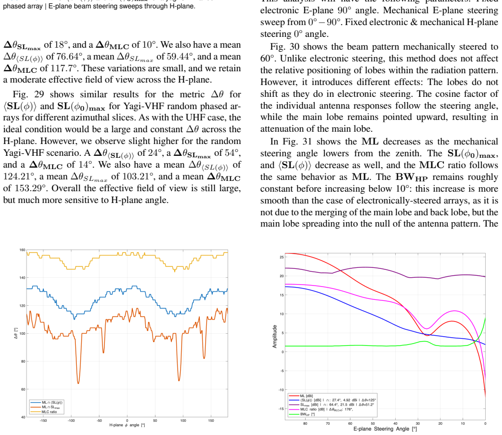
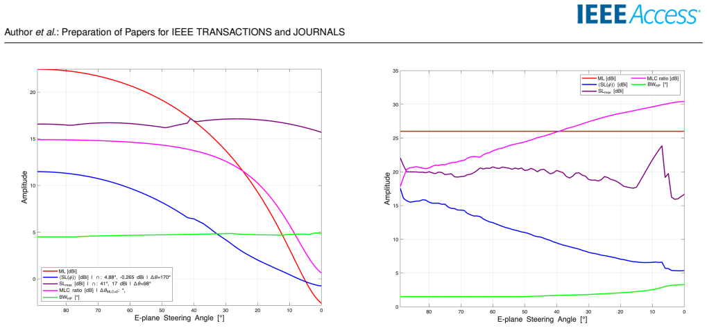
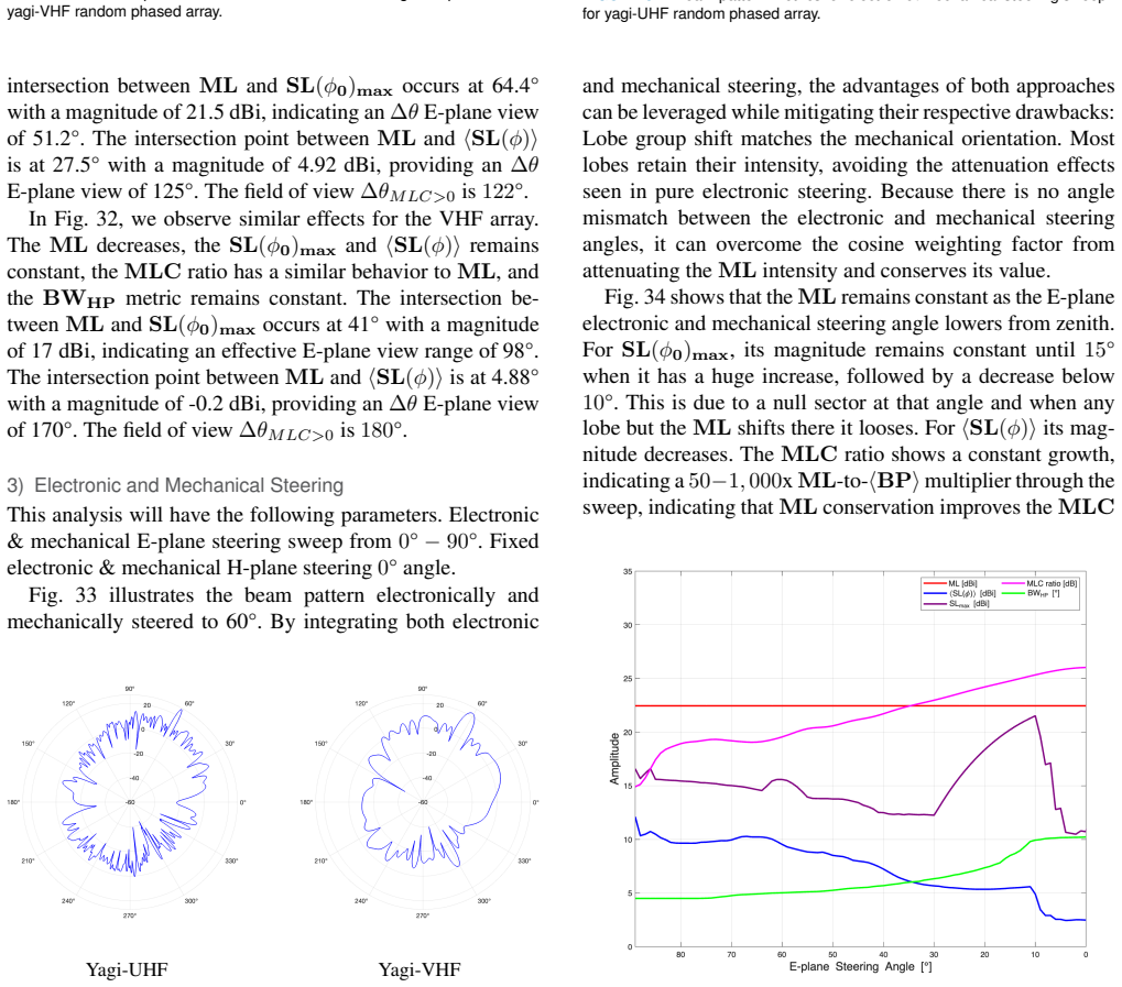
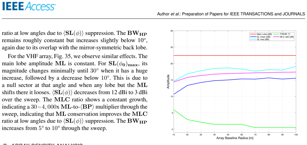
Frequency & Radiative Analysis of Random Yagi-UHF/VHF Phased Array
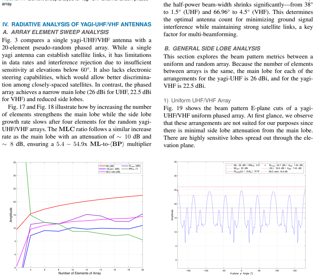
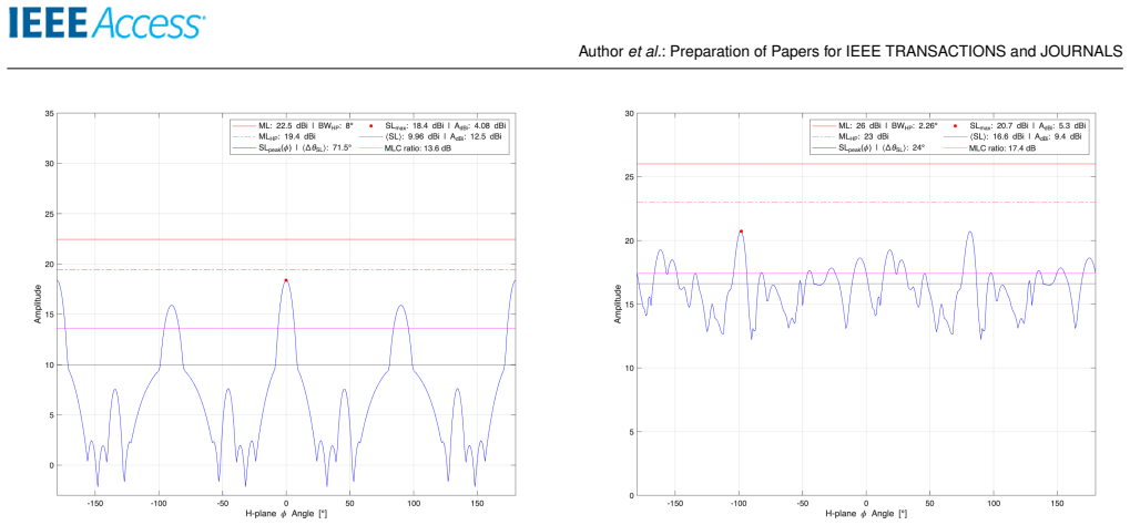
Pith reviewed 2026-05-10 15:59 UTC · model grok-4.3
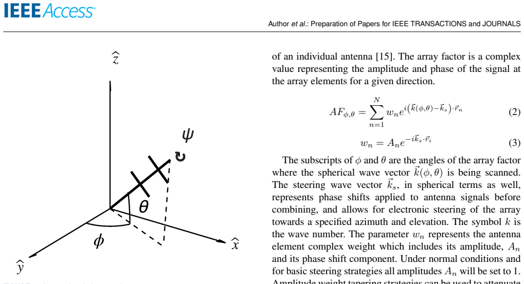
The pith
A pseudo-random layout of dual-polarized Yagi antennas enables a low-cost phased array to track multiple sources with electronic and multi-beam steering.
A machine-rendered reading of the paper's core claim, the machinery that carries it, and where it could break.
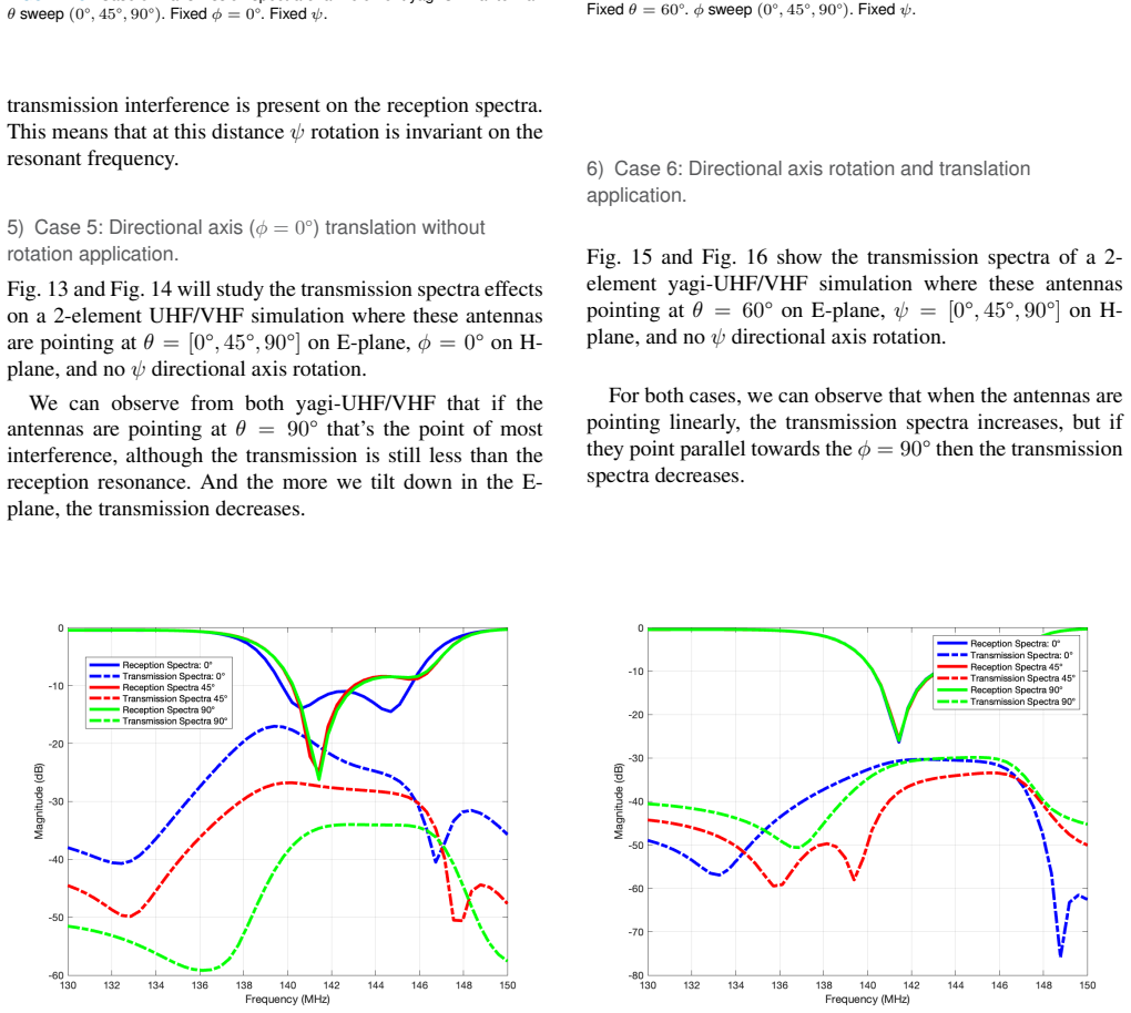
Core claim
The paper claims that a phased array ground station built from 20 pairs of dual-polarized Yagi antennas in a pseudo-random layout can achieve multi-source tracking, multi-beamforming, electronic steering, easy scaling, and low cost. These capabilities are examined by contrasting random and uniform layouts and by carrying out side-lobe analysis across elevation and azimuth, an element-sweep study of scaling, separate electronic, mechanical, and electro-mechanical beam-steering analyses, array-density assessment, and reception/transmission spectra analysis.
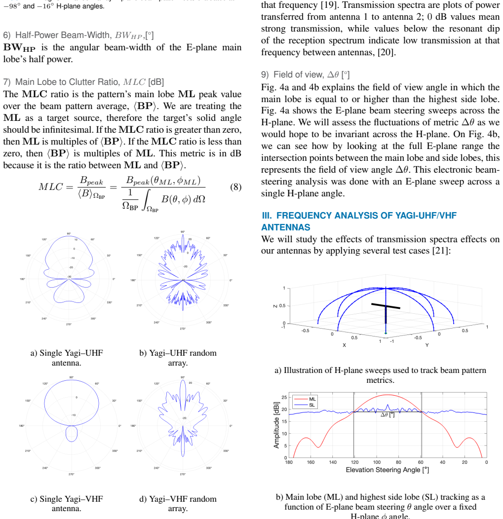
What carries the argument
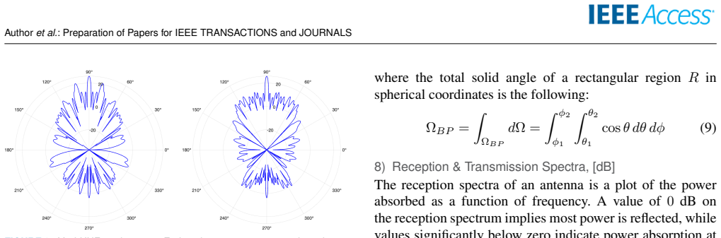
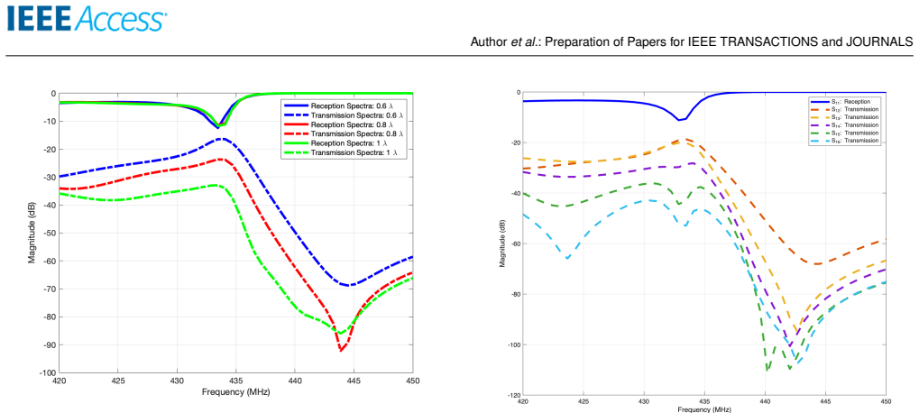
The pseudo-random layout of the 20-pair dual-polarized Yagi elements, used to compare radiation parameters against uniform distributions and to support the listed beam-steering and scaling analyses.
If this is right
- The array can be expanded by adding elements while preserving the ability to form multiple beams.
- Electronic steering removes the need for continuous mechanical movement when tracking sources.
- Multi-beamforming allows one station to monitor or communicate with several sources at once.
- Low-cost construction and simple scaling make the design practical for distributed or resource-limited deployments.
- Reception and transmission spectra results can guide frequency-specific optimizations for UHF or VHF operation.
Where Pith is reading between the lines
- If side-lobe suppression improves with the random layout, the same placement strategy could be tested at neighboring frequency bands where interference is a concern.
- The electro-mechanical steering analysis suggests hybrid control systems that switch between fast electronic adjustments and slower mechanical repositioning for energy efficiency.
- Density analysis may indicate optimal spacing that balances gain against mutual coupling, offering a design rule for similar Yagi arrays.
- Spectra analysis could reveal bandwidth limits that determine whether the array suits narrowband or wideband applications.
Load-bearing premise
That the planned comparisons of random and uniform distributions together with the listed analyses will produce actionable insights into the advantages of the pseudo-random layout under real conditions.
What would settle it
If the completed side-lobe, scaling, steering, and spectra analyses show no measurable improvement in multi-beam performance or side-lobe control for the pseudo-random layout relative to a uniform layout, or if the array fails to support simultaneous tracking of multiple sources.
Figures
read the original abstract
This paper investigates a phased array ground station capable of tracking multiple sources, multi-beamforming, electronic steering, easy scaling, and low cost. The project will develop a 20-pair dual-polarized yagi-UHF/VHF phased array with a pseudo-random layout, comparing parameters of random and uniform distributions. We will present several analyses: general analysis for side lobes across both elevation and azimuth, analysis of scaling with number of elements ("element sweep"), electronic beam steering analysis, mechanical beam steering analysis, electro-mechanical beam steering analysis, array density analysis, and reception/transmission spectra analysis.
Editorial analysis
A structured set of objections, weighed in public.
Referee Report
Summary. The manuscript outlines plans to develop a 20-pair dual-polarized Yagi-UHF/VHF phased array ground station using a pseudo-random layout. It states that the project will compare random versus uniform element distributions and will present analyses of side-lobe levels (elevation and azimuth), element scaling, electronic beam steering, mechanical beam steering, electro-mechanical steering, array density, and reception/transmission spectra. The text contains no equations, simulations, measured data, or completed results.
Significance. Low-cost, scalable phased arrays for multi-source tracking in the UHF/VHF bands are of practical interest for instrumentation. If the described analyses were executed with reproducible simulations or measurements that quantified advantages of the pseudo-random layout, the work could provide useful design guidance. No such results are present, so significance cannot be assessed from the current manuscript.
major comments (2)
- [Abstract] Abstract and full text: the central claims that the array 'is capable of' multi-source tracking, multi-beamforming, electronic steering, and low-cost scaling are unsupported assertions. The manuscript uses only future tense ('will develop', 'will present') and supplies no executed side-lobe analysis, element-sweep results, beam-pattern calculations, or any other quantitative evaluation.
- No sections, equations, figures, or tables exist in the manuscript. Without at least one completed analysis (e.g., the promised random-versus-uniform side-lobe comparison or element-sweep data), the asserted performance advantages remain untested and cannot be evaluated for correctness or novelty.
Simulated Author's Rebuttal
We thank the referee for the detailed review. We agree that the submitted manuscript is a high-level description of planned work rather than a completed study with executed analyses or quantitative results. The text is written entirely in future tense and contains no equations, simulations, or data. We will revise the manuscript substantially to address these issues by adding preliminary simulation results, equations, and figures while clarifying the scope as a design and analysis plan.
read point-by-point responses
-
Referee: [Abstract] Abstract and full text: the central claims that the array 'is capable of' multi-source tracking, multi-beamforming, electronic steering, and low-cost scaling are unsupported assertions. The manuscript uses only future tense ('will develop', 'will present') and supplies no executed side-lobe analysis, element-sweep results, beam-pattern calculations, or any other quantitative evaluation.
Authors: We acknowledge that the claims are presented as project goals rather than demonstrated outcomes, and the future tense accurately reflects the current state of the work. In revision we will rephrase the abstract and introduction to state these as intended capabilities of the planned array, supported by initial simulations. We will add a new section with beam-pattern calculations and side-lobe comparisons between random and uniform layouts to provide quantitative grounding for the design choices. revision: yes
-
Referee: [—] No sections, equations, figures, or tables exist in the manuscript. Without at least one completed analysis (e.g., the promised random-versus-uniform side-lobe comparison or element-sweep data), the asserted performance advantages remain untested and cannot be evaluated for correctness or novelty.
Authors: The current manuscript is limited to an outline of the project. We agree that this prevents evaluation of novelty or correctness. The revised version will include dedicated sections with the array factor equations, simulation methodology, at least one completed analysis (random vs. uniform side-lobe levels in elevation and azimuth), element-scaling results, and accompanying figures and tables. This will allow direct assessment of the pseudo-random layout advantages. revision: yes
Circularity Check
No derivation chain or equations present; paper is a forward-looking project plan
full rationale
The manuscript describes intended future work on a phased array but supplies no equations, derivations, fitted parameters, predictions, or completed analyses. Without any load-bearing mathematical steps or results, there is no derivation chain that could reduce to its own inputs by construction, self-citation, or renaming. The content is therefore self-contained as a statement of planned activities.
Axiom & Free-Parameter Ledger
Reference graph
Works this paper leans on
-
[1]
(2022) Launch cost per kilogram of payload
CSIS Aerospace Security Project. (2022) Launch cost per kilogram of payload. Processed by Our World in Data. [Online]. Available: https://ourworldindata.org/grapher/cost-space-launches-low-earth-orbit
work page 2022
-
[2]
United States Space Force. (2023) Objects in space. Processed by Our World in Data. [Online]. Available: https://ourworldindata.org/grapher/space-objects-by-orbit
work page 2023
-
[3]
W. L. Stutzman and G. A. Thiele, Antenna Theory and Design, 3rd ed. New York, NY , USA: Wiley, 2013. 12 VOLUME 4, 2016 Authoret al.: Preparation of Papers for IEEE TRANSACTIONS and JOURNALS
work page 2013
-
[4]
C. A. Balanis, Antenna Theory: Analysis and Design, 3rd ed. New York, NY , USA: Wiley, 2005
work page 2005
-
[5]
Developing a uhf/vhf phased-array satellite ground station,
B. K. Cole, “Developing a uhf/vhf phased-array satellite ground station,” Ph.D. dissertation, University of Texas Rio Grande Valley, 2020. [Online]. Available: https://scholarworks.utrgv.edu/etd/643
work page 2020
-
[6]
A random phased-array for mr-guided transcranial ultrasound neuromodulation in non-human primates,
V . Chaplin, M. A. Phipps, and C. F. Caskey, “A random phased-array for mr-guided transcranial ultrasound neuromodulation in non-human primates,” Physics in Medicine and Biology, vol. 63, no. 10, p. 105016, 2018
work page 2018
-
[7]
M. Zubair and R. Dickinson, “3d synthetic aperture imaging with a therapeutic spherical random phased array for transcostal applications,” Physics in Medicine and Biology, vol. 66, 2021
work page 2021
-
[8]
Phase-only excited random antenna arrays,
G. Buonanno and R. Solimene, “Phase-only excited random antenna arrays,” in Proc. PIERS, Toyama, Japan, 2018, pp. 1842–1846
work page 2018
-
[9]
Reduction of phase shifters in planar phased arrays using novel random subarray techniques,
J. L. Valle, M. A. Panduro, C. del Río Bocio, C. A. Brizuela, and D. H. Covarrubias, “Reduction of phase shifters in planar phased arrays using novel random subarray techniques,” Applied Sciences, vol. 14, no. 13, p. 5917, 2024. [Online]. Available: https://doi.org/10.3390/app14135917
-
[10]
Randomly spaced phased arrays with large interelement spacings,
V . Corcoran, “Randomly spaced phased arrays with large interelement spacings,” in Proc. IEEE APS Int. Symp., vol. 13, 1975, pp. 309–310
work page 1975
-
[11]
C. Wang, Y . Wang, X. Yang, W. Gao, C. Jiang, L. Wang, Y . Zhang, and M. Wang, “Effect of randomness in element position on performance of communication array antennas in internet of things,” Wireless Communi- cations and Mobile Computing, vol. 2018, p. 6492143, 2018
work page 2018
-
[12]
Phased array antennas for satellite com- munications,
M. Q. Alolyania and K. M. Harb, “Phased array antennas for satellite com- munications,” in Proc. IEEE 12th Control and System Graduate Research Colloquium (ICSGRC), 2021, pp. 150–153
work page 2021
-
[13]
Phased array metantennas for satellite communications,
Z. N. Chen, Q. Xianming, X. Tang, W. Liu, and R. Xu, “Phased array metantennas for satellite communications,” IEEE Communications Maga- zine, vol. 60, pp. 46–50, 2022
work page 2022
-
[14]
H. L. V . Trees, Detection, Estimation, and Modulation Theory, Part IV: Optimum Array Processing. New York, NY , USA: Wiley, 2002
work page 2002
-
[15]
R. J. Mailloux, Phased Array Antenna Handbook, 2nd ed. Boston, MA, USA: Artech House, 2005
work page 2005
-
[16]
D. H. Johnson and D. E. Dudgeon, Array Signal Processing: Concepts and Techniques. Upper Saddle River, NJ, USA: Prentice Hall, 1993
work page 1993
-
[17]
Reduction of phase shifters in planar phased arrays using novel random subarray techniques,
J. L. Valle, M. A. Panduro, C. del Rio Bocio, C. A. Brizuela, and D. H. Covarrubias, “Reduction of phase shifters in planar phased arrays using novel random subarray techniques,” Applied Sciences, vol. 14, no. 13, p. 5917, 2024
work page 2024
-
[18]
(2024) Radiation pattern definitions
Antenna-Theory.com. (2024) Radiation pattern definitions. Ac- cessed: Oct. 28, 2024. [Online]. Available: https://www.antenna- theory.com/basics/radPatDefs.php
work page 2024
-
[19]
Definition and misuse of return loss,
T. S. Bird, “Definition and misuse of return loss,” IEEE Antennas and Propagation Magazine, vol. 51, no. 2, pp. 166–167, Apr. 2009
work page 2009
-
[20]
(2024) Scattering parameters (or s- parameters)
MathWorks. (2024) Scattering parameters (or s- parameters). Accessed: Oct. 28, 2024. [Online]. Avail- able: https://la.mathworks.com/help/rfpcb/gs/scatterring-parameters-or-s- parameters
work page 2024
-
[21]
J. Doane. (2024) Visualizing crosstalk in pcbs. In Compliance Magazine, Accessed: Oct. 28, 2024. [Online]. Available: https://incompliancemag.com/visualizing-crosstalk-in-pcbs/ LUIS M. BRESreceived his PhD. in physics in 2026 at the University of Texas Rio Grande Valley (UTRGV), his M.S. in physics in 2021 at UTRGV , and his B.S. in physics in 2018 at UTR...
work page 2024
discussion (0)
Sign in with ORCID, Apple, or X to comment. Anyone can read and Pith papers without signing in.