Quantum computational displacement sensing
Pith reviewed 2026-05-10 15:03 UTC · model grok-4.3
The pith
Parameterized quantum circuits around a displacement sensor classify its class label more accurately than estimating the displacement first and processing classically.
A machine-rendered reading of the paper's core claim, the machinery that carries it, and where it could break.
Core claim
Quantum computational displacement sensing uses parameterized quantum circuits placed before and after a physical displacement acting on an oscillator; the circuits are trained to map the unknown displacement directly onto the ground or excited state of a coupled qubit, so that a single qubit measurement yields the binary class label without ever estimating the displacement value itself.
What carries the argument
Parameterized quantum circuits inserted before and after the displacement sensing operation, which encode the classification objective into the unitary evolution so the qubit readout directly outputs the predicted label.
If this is right
- Deeper circuits with more parameters systematically increase expressivity and classification accuracy for the same sensing task.
- When only a function or property of the sensed signal is required, the quantum-computational route avoids the overhead of full signal reconstruction.
- The same pre- and post-sensing circuit structure can be applied to other physical parameters beyond displacement.
- Task-specific training of the circuits can be performed in simulation and then transferred to hardware for immediate experimental use.
Where Pith is reading between the lines
- If the observed advantage persists at larger circuit sizes, quantum computational sensing may become preferable for any sensing task whose output is a low-dimensional label or decision rather than a high-dimensional waveform.
- The approach reframes quantum sensors as programmable processors whose native operation is part of an end-to-end computation rather than a standalone metrology device.
- Similar pre- and post-processing circuits could be tested on other hardware platforms to determine how platform-specific noise affects the transfer of in-silico-trained models.
Load-bearing premise
Circuits optimized entirely in noiseless simulation will continue to deliver their reported accuracy advantage when run on real superconducting hardware despite decoherence, calibration drift, and simulation-reality mismatch.
What would settle it
An experiment in which the quantum computational protocol's classification accuracy falls to or below the best conventional estimation-plus-classical-postprocessing accuracy on the same displacement-classification tasks.
Figures






read the original abstract
Quantum computational sensing (QCS) combines quantum sensing with quantum computing to extract task-relevant information from the physical world. QCS can in principle achieve an accuracy advantage for specific tasks versus the alternative of raw-signal estimation using conventional quantum sensing followed by task-specific classical postprocessing. Here we report the experimental demonstration of quantum computational displacement sensing (QCDS) with a superconducting circuit comprising a qubit coupled to an oscillator. We consider binary classification sensing tasks, where the goal is to predict the class label of a single complex-valued displacement sensed once by the oscillator. Rather than estimating the displacement, our computational-sensing protocol -- using parameterized quantum circuits before and after sensing -- attempts to determine the binary class label using quantum processing and map it onto the ground or excited state of the qubit. A single measurement of the qubit directly outputs the prediction. We implemented circuits with up to 24 entangling gates and 38 free parameters, which were trained in silico. We show that increasing the circuit depth systematically improves expressivity and classification accuracy. We experimentally obtained an accuracy advantage over a suite of protocols that first use conventional quantum sensing to estimate the displacement before using classical postprocessing to perform prediction. For certain tasks, our protocol achieves a 15-percentage-points higher classification accuracy than the best conventional approach considered. Our results establish the feasibility of quantum computational sensing with noisy superconducting hardware and illustrate how integrating quantum computation with quantum sensing can enhance performance when the goal is to estimate a property or function of a signal rather than to estimate the signal.
Editorial analysis
A structured set of objections, weighed in public.
Referee Report
Summary. The manuscript reports an experimental realization of quantum computational displacement sensing (QCDS) on a superconducting qubit-oscillator system. Parameterized quantum circuits (up to 24 entangling gates and 38 free parameters, trained entirely in classical simulation) are inserted before and after the displacement sensing operation to perform direct binary classification of the displacement via a single qubit measurement. The central experimental claim is that this integrated quantum-computational protocol achieves up to 15 percentage points higher classification accuracy than conventional quantum sensing followed by classical post-processing pipelines, with accuracy improving systematically as circuit depth increases. The work positions this as a demonstration of the feasibility of quantum computational sensing on noisy hardware.
Significance. If the reported accuracy advantage is statistically robust, this would constitute a meaningful experimental step toward practical quantum computational sensing. It supplies concrete hardware evidence that task-specific quantum processing can outperform the conventional pipeline of full signal estimation plus classical post-processing, at least for selected binary classification tasks. The systematic depth-scaling study and the direct hardware implementation are strengths that, if properly validated, support the broader paradigm of integrating quantum computation with quantum sensing.
major comments (2)
- [Experimental Results] Experimental Results section: The headline claim that the protocol 'achieves a 15-percentage-points higher classification accuracy than the best conventional approach considered' is presented without error bars, confidence intervals, the number of experimental shots or repetitions, or any description of the statistical procedure used to obtain the figure. This information is load-bearing for the central experimental result and is required to assess whether the advantage is statistically significant or potentially affected by post-hoc task selection.
- [Circuit Training and Hardware Implementation] Circuit Training and Hardware Implementation section: Circuits with up to 38 parameters and 24 entangling gates are trained exclusively in silico, yet the manuscript contains no quantitative simulated-versus-experimental accuracy comparison for the same circuits. Without this comparison, it is impossible to confirm that the claimed 15 pp advantage survives the accumulated decoherence, gate infidelity, and model mismatch expected on the superconducting device.
minor comments (1)
- [Methods] Figure captions and methods: The description of the parameterized circuit ansatz would benefit from an explicit statement of the gate set and the precise parameterization (e.g., which angles are trainable) to facilitate independent reproduction.
Simulated Author's Rebuttal
We thank the referee for their careful reading and constructive comments. We appreciate the recognition of the experimental demonstration and the systematic depth study. We address each major comment below and will revise the manuscript to incorporate the requested clarifications and additions.
read point-by-point responses
-
Referee: [Experimental Results] Experimental Results section: The headline claim that the protocol 'achieves a 15-percentage-points higher classification accuracy than the best conventional approach considered' is presented without error bars, confidence intervals, the number of experimental shots or repetitions, or any description of the statistical procedure used to obtain the figure. This information is load-bearing for the central experimental result and is required to assess whether the advantage is statistically significant or potentially affected by post-hoc task selection.
Authors: We agree that these statistical details are essential for assessing the robustness of the central claim. In the revised manuscript we will add error bars to the reported accuracies, computed via binomial statistics from the finite shot counts. We will explicitly state the number of shots per circuit (typically several thousand) and the number of independent hardware repetitions. We will also describe the statistical procedure used and confirm that the observed advantage remains statistically significant. The binary classification tasks were defined a priori from the sensing scenario and were not selected post-hoc. revision: yes
-
Referee: [Circuit Training and Hardware Implementation] Circuit Training and Hardware Implementation section: Circuits with up to 38 parameters and 24 entangling gates are trained exclusively in silico, yet the manuscript contains no quantitative simulated-versus-experimental accuracy comparison for the same circuits. Without this comparison, it is impossible to confirm that the claimed 15 pp advantage survives the accumulated decoherence, gate infidelity, and model mismatch expected on the superconducting device.
Authors: We acknowledge this gap in the original presentation. Although the circuits were trained in simulation, we possess the corresponding simulated accuracies for the trained parameter sets. In the revision we will add a direct quantitative comparison (in the main text or as a supplementary figure) of simulated versus experimental classification accuracies for the same circuits. This will quantify the degradation due to hardware noise while showing that the advantage over conventional sensing-plus-postprocessing pipelines is retained on the device. revision: yes
Circularity Check
No circularity; experimental results are directly measured
full rationale
The manuscript describes an experimental protocol for quantum computational displacement sensing using a superconducting circuit. Parameterized circuits with up to 38 parameters are trained in silico and then executed on hardware to perform binary classification of displacements. The accuracy advantage is reported from direct experimental measurements comparing the quantum protocol to conventional estimation followed by classical postprocessing. There is no derivation chain involving predictions or first-principles results that reduce to the inputs by construction. No self-citations are load-bearing for the central claim, and the work relies on empirical data rather than theoretical self-consistency.
Axiom & Free-Parameter Ledger
free parameters (1)
- circuit parameters =
up to 38
axioms (2)
- standard math Standard quantum mechanics governs the qubit-oscillator system and gate operations.
- domain assumption In-silico training accurately models the hardware noise and dynamics for parameter optimization.
Reference graph
Works this paper leans on
-
[1]
Arbitrary qubit rotations When performing arbitrary qubit rotations, we consider the cavity drive signals to be turned off (ε= 0). We define the qubit drive waveform as: Ω(t) = Aπ 2 eiϕhΩ(t),(D2) whereAdefines the amplitude of the pulse,ϕits phase, andh Ω(t) its temporal waveform (see Appendix C 1). For a pulse of lengtht p, the pulse waveform is normaliz...
-
[2]
Echoed conditional displacement (ECD) gate The ECD gate is composed of three elementary operations. The first operation applies a coherent driveε(t) to the oscillator, whose action can be denoted as a unitary operationU ε. This is followed by aπ-pulse on the qubit defined asR π ≡R(θ=π, ϕ= 0) (see Appendix D 1). Lastly, we apply a second coherent driveε ′(...
-
[3]
Fromt 0 tot − m a storage driveε(t) is applied
-
[4]
Fromt − m tot + m a qubitπ-pulse is applied
-
[5]
We typically considerε ′(t) =−ε(t)
Finally, fromt + m tot f a second storage driveε ′(t) is applied. We typically considerε ′(t) =−ε(t). For the first storage cavity drive, the evolution is given by Eq. (D19), reproduced below: |ψ(t− m)⟩=U ε|ψ(t0)⟩=−i h ˆD(αg(t− m))e−iτ χ 2 ˆa†ˆae−iϕg ˆD†(αg(t0))|g⟩⟨g|+ ˆD(αe(t− m))e+iτ χ 2 ˆa†ˆae−iϕe ˆD†(αe(t0))|e⟩⟨e| i |ψ(t0)⟩. (D24) Upon completion of t...
-
[6]
We therefore obtain analytic forms of the accrued drive-induced phases: ϕg(t) = |ε| 2 αg(0)I ∗ 1(t)e−iϕε +α ∗ g(0)I1(t)e+iϕε − i 2 |ε|2 (I2(t)− I ∗ 2(t)) (D37a) ϕe(t) = |ε| 2 αe(0)I1(t)e−iϕε +α ∗ e(0)I ∗ 1(t)e+iϕε − i 2 |ε|2 (I ∗ 2(t)− I 2(t)) (D37b) Eqs. (D33a), (D33b) and Eqs. (D37a), (D37b) provide analytic solutions for the drive-induced displacements...
-
[7]
Sensing operation We implement the sensing displacement using a pulseε s(t), of the pulse shape used in the calibration of the AWG amplitude to displacement (see Appendix C 1), with the amplitude and phase determined by the dataset. Due to the analog nature of the pulse, this operation imparts a small conditional displacement, orthogonal to the direction ...
work page 2048
-
[8]
Overview In this Appendix section we provide details of various displacement sensing baselines considered. Table III sum- marizes the benefits and drawbacks of these displacement sensing baselines, along with our QCDS protocol, when used for the task of binary classification of displacements. When the quantum computational displacement sensor achieves a b...
-
[9]
Directly outputs the class prediction
-
[10]
Performance increases with circuit depthN
-
[11]
Quantum circuit requires to be trained for each task
-
[12]
Sensitive to small displacements
Performance limited by qubit-readout fidelity Cat-state sensor 1. Sensitive to small displacements
-
[13]
Simple to implement in experiment
-
[15]
Sensitivity – dynamic range tradeoff
-
[16]
Performance limited by qubit-readout fidelity Compass-state sensor
-
[19]
Limited expressive capacity
-
[20]
Performance limited by qubit-readout fidelity Phase-preserving amplifier and classical postprocessing backend
-
[23]
Limited by the fundamental noise introduced by the amplifier
-
[24]
Classical postprocessing required to be trained for each task Squeezed probe-state, phase-sensitive amplifier and classical postprocessing backend
-
[25]
Sensitive to small displacements
-
[26]
High expressive capacity of the single-component displacement
-
[27]
Sensitive to single-component of displacement
-
[28]
Classical postprocessing required to be trained for each task GKP probe-state, quantum phase estimation and classical postprocessing backend
-
[30]
Sensitive to both components of displacement
-
[31]
Limited dynamic range
-
[32]
Classical postprocessing required to be trained for each task Two-mode squeezed probe-state, phase-sensitive amplifiers and classical postprocessing backend
-
[33]
High expressive capacity
-
[34]
Performance increases with two-mode squeezing
-
[35]
Hard to implement in experiment with high efficiency
-
[36]
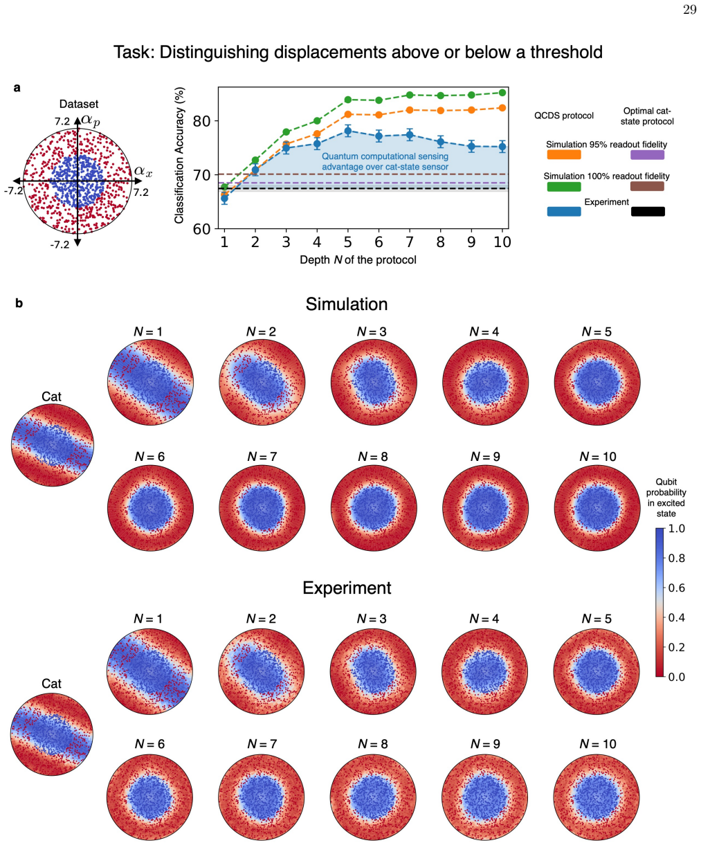
Classical postprocessing required to be trained for each task TABLE III.Benefits and drawbacks of different protocols for classifying displacements.The first row is the quantum computational displacement sensor introduced in this work, while the rest are examples of conventional displacement sensing protocols In Fig, 19, we plot the response of various pr...
-
[37]
Quantum computational displacement sensor In this subsection, we discuss the implementation of our quantum computational sensor for this task. In Fig. 20a, we plot the experimental classification accuracy of the protocols as a function of the circuit depthN. The best performance, acrossN, is plotted in Fig. 4. For our experiment, this is usually theN= 12 ...
-
[38]
This protocol can be realized for aN= 1 version of the QCDS protocol
Cat-state sensor The cat-state sensing protocol measures a single component of the sensed displacement by mapping it onto the qubit phase [10]. This protocol can be realized for aN= 1 version of the QCDS protocol. In general, this proceeds by preparing the qubit in the|+⟩state. Then, an echoed conditional displacement gate entangles the qubit with the cav...
-
[39]
Compass-state sensor Another approach for conventional quantum sensing of displacements is using compass states [31], which belong to the family of generalized Schr¨ odinger cat-states. The compass-state sensing protocol relies on the fact that a compass state that is displaced byD(α) is quasiorthogonal to the undisplaced compass state on a scale set by 1...
-
[40]
Phase-preserving amplifier and classical postprocessing backend A conventional sensing strategy is to perform heterodyne measurement of the oscillator, which provides unbiased estimates of its position and momentum (eαx,eαp) in a single shot [18]. The advantage of this technique is its simplicity: based on the estimate, further postprocessing tasks can be...
-
[41]
Squeezed probe-state, phase-sensitive amplifier and classical postprocessing backend Another conventional sensing strategy which we use as a benchmark is one which only measures one component of the displacement. This protocol was implemented in the second phase of the HAYSTAC experiment, which provided a sensing advantage since the axis of the displaceme...
-
[42]
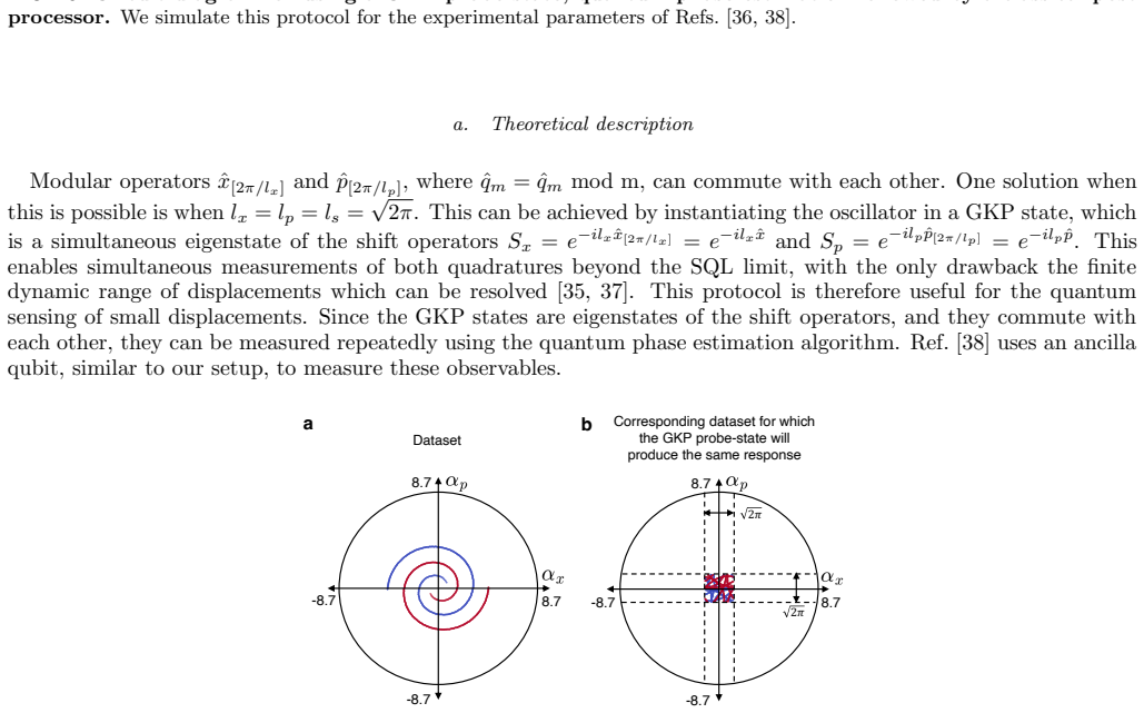
Gottesman–Kitaev–Preskill (GKP) probe-state, quantum phase estimation and classical postprocessing backend A protocol can estimate both position and momentum beyond the limit set by the uncertainty principle by instead measuring their modular counterparts. In this subsection, we simulate the performance of a quantum sensing protocol based on using the GKP...
-
[43]
multi-mode conditional displacement gate
Two-mode squeezed probe state, phase-sensitive amplifiers and classical postprocessing backend Two-mode squeezing (TMS) provides a resource to enable sub-vacuum-noise estimation of non-commuting quadra- tures of a sensed displacement [39, 40]. In this section we provide theoretical details of this TMS scheme for displace- ment sensing, and of the classica...
discussion (0)
Sign in with ORCID, Apple, or X to comment. Anyone can read and Pith papers without signing in.