Single Plane Spatial Mode Sorter
Pith reviewed 2026-05-10 12:16 UTC · model grok-4.3
The pith
A single phase mask in one plane sorts orthogonal spatial modes from multiple families into separate outputs with near-zero crosstalk.
A machine-rendered reading of the paper's core claim, the machinery that carries it, and where it could break.
Core claim
A single-plane phase pattern can be analytically derived that maps any chosen set of M orthogonal spatial modes to M spatially separated output locations with almost no crosstalk. For the special case of OAM modes with zero radial index the pattern reduces to the known fork grating. In the limit of large M the design yields an analytic expression for sorting every member of a given mode family. The power reaching each output is 1/M, shown to be the maximum possible under the constraint of fixed detector positions.
What carries the argument
The single-plane phase mask whose transmission function is obtained by solving for the phases that steer each input mode to a distinct output coordinate while preserving orthogonality.
If this is right
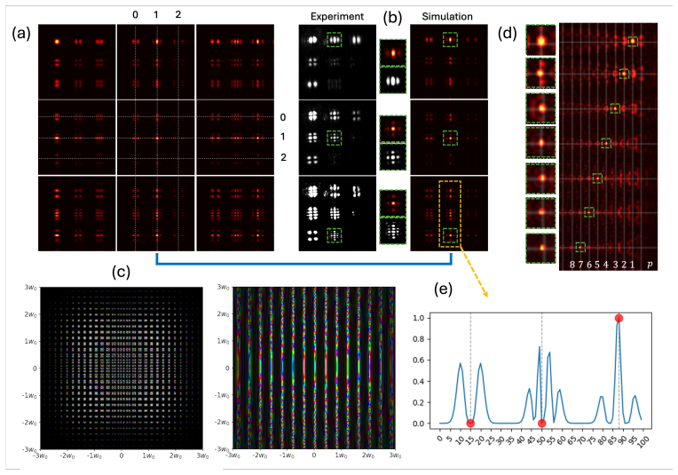
- The device sorts HG, LG, and BG modes in a single plane without needing multiple elements.
- Reversing the sorter turns a Gaussian input into any desired mode from the family.
- For orbital angular momentum modes with zero radial index the design reproduces the standard fork grating.
- Power efficiency is bounded by 1/M and this bound is tight for standard output geometries.
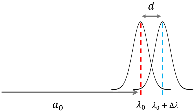
- The sorter remains functional across a modest wavelength range before diffraction and phase errors degrade performance.
Where Pith is reading between the lines
- The approach may allow compact mode-multiplexed links in both classical and quantum optics by replacing bulk mode sorters.
- Because the mask is analytic, it can be fabricated once and used for any chosen subset of a mode family without redesign.
- Sensitivity analysis in the paper implies that random phase noise on the mask or input must stay below a few percent of a radian to keep crosstalk low.
- Operating the device in the large-M limit could provide a continuous spatial-mode demultiplexer for beams that contain many modes.
Load-bearing premise
A fixed phase pattern chosen in advance can map every orthogonal input mode to a unique non-overlapping output spot without residual interference that grows with wavelength or noise.
What would settle it
An experiment in which measured crosstalk between any two sorted modes exceeds a few percent or the measured power per channel falls significantly below the predicted 1/M value.
Figures




read the original abstract
A mode sorter separates a set of M orthogonal spatial modes in a shared input channel into M different output channels. Here we present an analytic derivation and experimental validation of a single plane device for sorting spatial modes from a diverse variety of mode families, including Hermite-Gaussian (HG), Laguerre-Gaussian (LG), Bessel-Gaussian (BG), with almost no cross-talk. This sorting capability is required for a wide range of applications that employ classical or quantum light. We also show that applying this design in order to sort a set of Orbital Angular Momentum (OAM) modes with zero radial index reproduces the well-known Fork grating configuration. Furthermore, by taking the limit of M -> inf, we present an analytical expression for sorting all the modes of a given family. By operating this device in reverse, it can be used to generate arbitrary modes, by illuminating it with a Gaussian beam. The power transmission coefficient for this sorter goes as 1/M and we provide a mathematical proof that this is optimal for any typical arrangement of the detector positions. We further study the sorter sensitivity to wavelength and random phase noise.
Editorial analysis
A structured set of objections, weighed in public.
Referee Report
Summary. The manuscript presents an analytic derivation of a single-plane phase mask that sorts M orthogonal spatial modes from families including HG, LG, BG, and OAM into spatially separated outputs with near-zero crosstalk. It includes experimental validation for these families, shows that the design reproduces the fork grating for OAM modes with zero radial index, derives an analytic expression for the M to infinity limit, demonstrates reverse operation for arbitrary mode generation from a Gaussian input, proves that the 1/M power transmission is optimal under typical detector geometries, and quantifies sensitivity to wavelength shifts and random phase noise.
Significance. If the central claims hold, the work offers a compact, analytically grounded single-plane solution for spatial mode sorting that applies across multiple mode bases and is supported by a tight optimality bound. This is relevant for quantum and classical applications in structured-light communications, imaging, and information processing, where multi-plane sorters are currently common. The explicit construction, mathematical proof of optimality, and experimental crosstalk data are strengths that could influence practical device implementations.
minor comments (3)
- The abstract states 'almost no cross-talk' and 'near-zero crosstalk' but does not quote the measured values or the exact threshold used; adding quantitative figures (e.g., from the experimental section) would improve precision.
- The wavelength and phase-noise sensitivity analysis is mentioned but the manuscript would benefit from a brief statement of the maximum acceptable phase-noise variance or wavelength detuning before crosstalk exceeds a stated level.
- In the reverse-operation section, the claim that arbitrary modes can be generated should specify the input beam waist and alignment tolerances required to maintain the reported fidelity.
Simulated Author's Rebuttal
We thank the referee for their detailed summary of the manuscript, positive assessment of its significance, and recommendation to accept. We are pleased that the central claims, analytic construction, optimality proof, and experimental results were found to be of interest for applications in structured light.
Circularity Check
No significant circularity in the derivation chain
full rationale
The paper supplies an explicit analytic construction for the single-plane phase mask derived from mode orthogonality and Fourier optics, together with an independent mathematical proof that the 1/M transmission bound is tight for the stated detector geometry. This proof does not reduce to a fitted parameter or self-referential definition. Reproduction of the known Fork grating for OAM modes functions as a consistency check rather than a load-bearing justification. The M to infinity limit and noise-sensitivity analysis are direct extensions of the same construction. No self-citation chain, ansatz smuggling, or renaming of known results is required for the central claims, which remain self-contained against standard Fourier optics and orthogonality.
Axiom & Free-Parameter Ledger
axioms (2)
- domain assumption Spatial modes of the listed families are mutually orthogonal.
- domain assumption A single-plane phase mask can implement the required mode-to-position mapping.
Reference graph
Works this paper leans on
-
[1]
Advances in high-dimensional quantum entanglement,
M. Erhard, M. Krenn, and A. Zeilinger, “Advances in high-dimensional quantum entanglement,” Nat. Rev. Phys.2, 365–381 (2020)
work page 2020
-
[2]
High-capacity millimetre-wave communications with orbital angular momentum multiplexing,
Y. Yan, G. Xie, M. P. J. Lavery,et al., “High-capacity millimetre-wave communications with orbital angular momentum multiplexing,” Nat. communications5, 4876 (2014)
work page 2014
-
[3]
Terabit-scale orbital angular momentum mode division multiplexing in fibers,
N. Bozinovic, Y. Yue, Y. Ren,et al., “Terabit-scale orbital angular momentum mode division multiplexing in fibers,” Science340, 1545–1548 (2013)
work page 2013
-
[4]
S. W. Hell and J. Wichmann, “Breaking the diffraction resolution limit by stimulated emission: stimulated-emission- depletion fluorescence microscopy,” Opt. letters19, 780–782 (1994)
work page 1994
-
[5]
Quantum theory of superresolution for two incoherent optical point sources,
M. Tsang, R. Nair, and X.-M. Lu, “Quantum theory of superresolution for two incoherent optical point sources,” Phys. Rev. X6, 031033 (2016)
work page 2016
-
[6]
The security of practical quantum key distribution,
V. Scarani, H. Bechmann-Pasquinucci, N. J. Cerf,et al., “The security of practical quantum key distribution,” Rev. modern physics81, 1301–1350 (2009)
work page 2009
-
[7]
High-dimensional quantum gates using full-field spatial modes of photons,
F. Brandt, M. Hiekkamäki, F. Bouchard,et al., “High-dimensional quantum gates using full-field spatial modes of photons,” Optica7, 98–107 (2020)
work page 2020
-
[8]
High-dimensional cryptography with spatial modes of light: tutorial,
E. Otte, I. Nape, C. Rosales-Guzmán,et al., “High-dimensional cryptography with spatial modes of light: tutorial,” J. Opt. Soc. Am. B37, A309–A323 (2020)
work page 2020
-
[9]
Opticalmodulation of electronbeams infree space,
F.J. G. deAbajo and A.Konečná, “Opticalmodulation of electronbeams infree space,” Phys.Rev. Lett.126, 123901 (2021)
work page 2021
-
[10]
Free-space optical communications,
V. W. S. Chan, “Free-space optical communications,” J. Light. technology24, 4750–4762 (2006)
work page 2006
-
[11]
Y. Zhou, B. Braverman, A. Fyffe,et al., “High-fidelity spatial mode transmission through a 1-km-long multimode fiber via vectorial time reversal,” Nat. communications12, 1866 (2021)
work page 2021
-
[12]
Modes and states in quantum optics,
C. Fabre and N. Treps, “Modes and states in quantum optics,” Rev. Mod. Phys.92, 035005 (2020)
work page 2020
-
[13]
Coldatomsincavity-generateddynamicalopticalpotentials,
H.Ritsch,P.Domokos,F.Brennecke,andT.Esslinger,“Coldatomsincavity-generateddynamicalopticalpotentials,” Rev. Mod. Phys.85, 553–601 (2013)
work page 2013
-
[14]
Continuous-variable optical quantum-state tomography,
A. I. Lvovsky and M. G. Raymer, “Continuous-variable optical quantum-state tomography,” Rev. Mod. Phys.81, 299–332 (2009)
work page 2009
-
[15]
Entanglement of the orbital angular momentum states of photons,
A. Mair, A. Vaziri, G. Weihs, and A. Zeilinger, “Entanglement of the orbital angular momentum states of photons,” Nature412, 313–316 (2001)
work page 2001
-
[16]
All-in-fiber dynamic orbital angular momentum mode sorting,
A. Alarcón, S. Gómez, D. Spegel-Lexne,et al., “All-in-fiber dynamic orbital angular momentum mode sorting,” (2023)
work page 2023
-
[17]
Arbitrary spatial mode sorting in a multimode fiber,
H. Defienne and D. Faccio, “Arbitrary spatial mode sorting in a multimode fiber,” Phys. Rev. A101, 063830 (2020)
work page 2020
-
[18]
High-dimensional spatial mode sorting and optical circuit design using multi-plane light conversion,
H. Kupianskyi, S. A. R. Horsley, and D. B. Phillips, “High-dimensional spatial mode sorting and optical circuit design using multi-plane light conversion,” APL Photonics8, 026101 (2023)
work page 2023
-
[19]
All-in-fiber dynamically reconfigurable orbital angular momentum mode sorting,
A. Alarcón, S. Gómez, D. Spegel-Lexne,et al., “All-in-fiber dynamically reconfigurable orbital angular momentum mode sorting,” ACS Photonics10, 3700–3707 (2023)
work page 2023
-
[20]
All-fiber fused directional coupler for highly efficient spatial mode conversion,
R. Ismaeel, T. Lee, B. Oduro,et al., “All-fiber fused directional coupler for highly efficient spatial mode conversion,” Opt. Express22, 11610–11619 (2014)
work page 2014
-
[21]
Oam beam generation in space and its applications: A review,
Y. Lian, X. Qi, Y. Wang,et al., “Oam beam generation in space and its applications: A review,” Opt. Lasers Eng.151, 106923 (2022)
work page 2022
-
[22]
Creation and detection of optical modes with spatial light modulators,
A. Forbes, A. Dudley, and M. McLaren, “Creation and detection of optical modes with spatial light modulators,” Adv. Opt. Photon.8, 200–227 (2016)
work page 2016
-
[23]
Programmable unitary spatial mode manipulation,
J.-F. Morizur, L. Nicholls, P. Jian,et al., “Programmable unitary spatial mode manipulation,” J. Opt. Soc. Am. A27, 2524 (2010)
work page 2010
-
[24]
Laguerre-gaussian mode sorter,
N. K. Fontaine, R. Ryf, H. Chen,et al., “Laguerre-gaussian mode sorter,” Nat. communications10, 1865 (2019)
work page 2019
-
[25]
Orbital angular momentum: origins, behavior and applications,
A. M. Yao and M. J. Padgett, “Orbital angular momentum: origins, behavior and applications,” Adv. Opt. Photon.3, 161–204 (2011)
work page 2011
-
[26]
Laser beams with screw dislocations in their wavefronts,
V. Y. Bazhenov, M. V. Vasnetsov, and M. S. Soskin, “Laser beams with screw dislocations in their wavefronts,” Jetp Lett52, 429–431 (1990)
work page 1990
-
[27]
Electron vortex beams with high quanta of orbital angular momentum,
B. J. McMorran, A. Agrawal, I. M. Anderson,et al., “Electron vortex beams with high quanta of orbital angular momentum,” Science331, 192–195 (2011)
work page 2011
-
[28]
A new way of producing electron vortex probes for stem,
J. Verbeeck, H. Tian, and A. Béché, “A new way of producing electron vortex probes for stem,” Ultramicroscopy113, 83–87 (2012)
work page 2012
-
[29]
Twisting light by nonlinear photonic crystals,
N. V. Bloch, K. Shemer, A. Shapira,et al., “Twisting light by nonlinear photonic crystals,” Phys. review letters108, 233902 (2012)
work page 2012
-
[30]
Efficient sorting of orbital angular momentum states of light,
G. C. G. Berkhout, M. P. J. Lavery, J. Courtial,et al., “Efficient sorting of orbital angular momentum states of light,” Phys. Rev. Lett.105, 153601 (2010)
work page 2010
-
[31]
R. Sahu, S. Chaudhary, K. Khare,et al., “Angular lens,” Opt. Express26, 8709–8718 (2018)
work page 2018
-
[32]
T. Durt, B.-G. Englert, I. Bengtsson, and K. Życzkowski, “On mutually unbiased bases,” Int. journal quantum information8, 535–640 (2010)
work page 2010
-
[33]
J. W. Goodman,Introduction to Fourier optics(Roberts and Company publishers, 2005)
work page 2005
-
[34]
Exact solution to simultaneous intensity and phase encryption with a single phase-only hologram,
E. Bolduc, N. Bent, E. Santamato,et al., “Exact solution to simultaneous intensity and phase encryption with a single phase-only hologram,” Opt. Lett.38, 3546–3549 (2013)
work page 2013
-
[35]
Self-configuring high-speed multi-plane light conversion,
J. C. A. Rocha, U. G. B¯utait˙e, J. Carpenter, and D. B. Phillips, “Self-configuring high-speed multi-plane light conversion,” arXiv preprint arXiv:2501.14129 (2025)
-
[36]
Quantum key distribution over a 40-db channel loss using superconducting single-photon detectors,
H. Takesue, S. W. Nam, Q. Zhang,et al., “Quantum key distribution over a 40-db channel loss using superconducting single-photon detectors,” Nat. photonics1, 343–348 (2007)
work page 2007
-
[37]
Integrated orbital angular momentum mode sorters on vortex fibers,
S. Lightman, I. Bleyhman, L. Somers,et al., “Integrated orbital angular momentum mode sorters on vortex fibers,” Opt. Lett.47, 3491–3494 (2022)
work page 2022
-
[38]
khencohen, “Singleplanespatialmodesorter,” GitHub (2024). [retrieved 22 December 2025]. A. Sorter Math derivation In this section, we describe the mathematical formulation of the setup and define the sorter. We further show mathematically why our suggested sorter works well and discuss its limitations. We start with the expression of the far field (Fraunh...
work page 2024
-
[39]
The intensity transmission coefficient goes as∼𝑂(𝑀−1)
-
[40]
The crosstalk depends on the square average of the inner-products between the modes
-
[41]
Typically, for orthogonal modes, the cross-talk is zero
-
[42]
1√ 𝑀 𝑀∑︁ 𝑚=1 𝑓𝑚(𝑥, 𝑦)𝑒 −𝑖 2𝜋 𝜆𝑧 ( 𝛼𝑚 𝑥+𝛽 𝑚 𝑦 ) # ∗
The separation should be larger than the bandwidth which can be approximated using M-squared. B. Sorter Optimality for one layer - a proof Given some arbitrary sorter𝑆(𝑥), we express the output field as: 𝐸𝑚, 𝜇 =𝐹𝑇 { 𝑓𝑚(𝑥, 𝑦)𝑆(𝑥, 𝑦) }𝜈 𝑥 = 𝛼𝜇 𝜆𝑧 ,𝜈 𝑦 = 𝛽𝜇 𝜆𝑧 .(24) Wewanttomaximizethisvalueasmuchaspossiblefor 𝑚=𝜇 andminimizefor 𝑚≠𝜇 . Focusing on the case wh...
discussion (0)
Sign in with ORCID, Apple, or X to comment. Anyone can read and Pith papers without signing in.