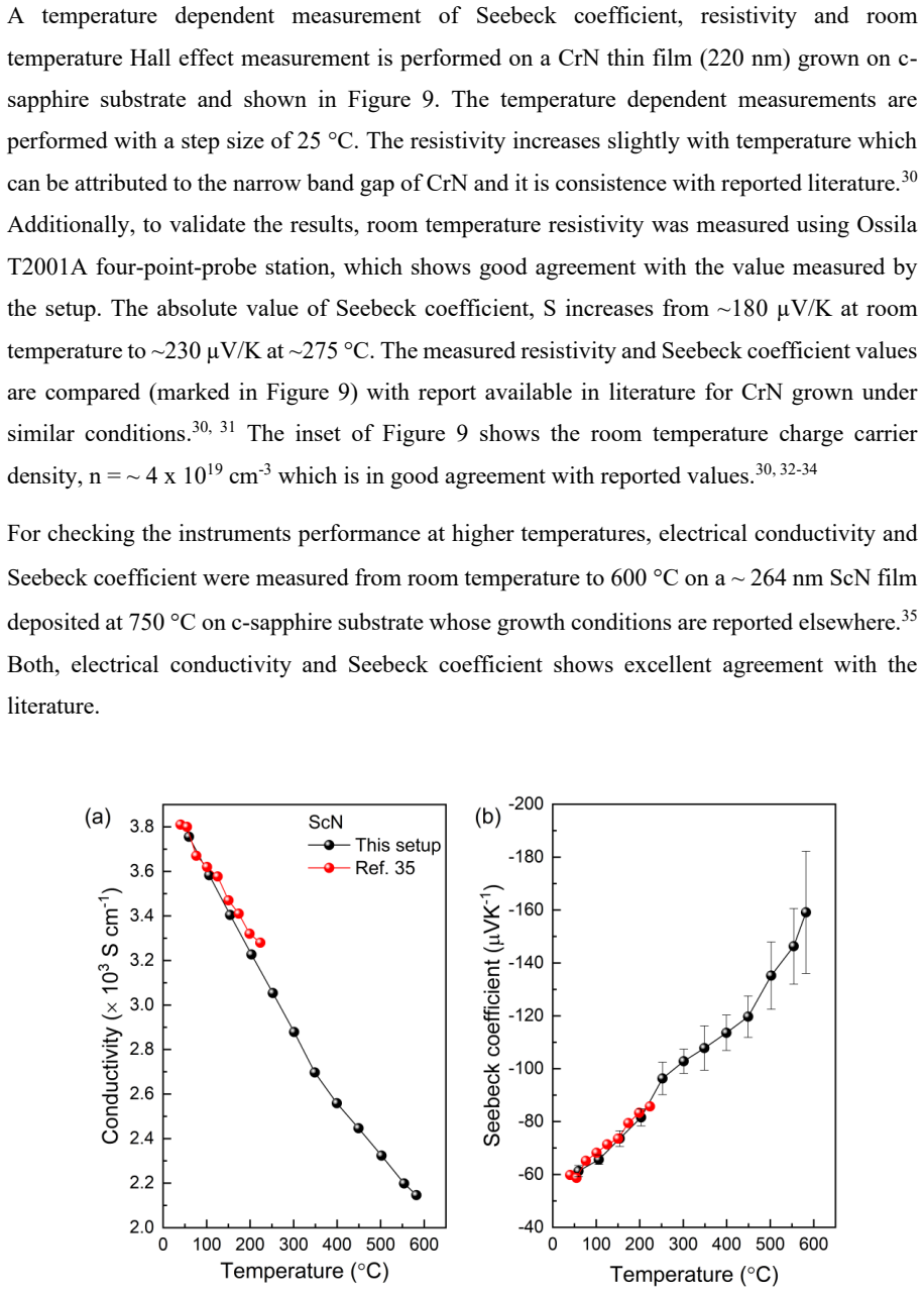
A single platform with van der Pauw geometry for measurement of Seebeck coefficient, resistivity, and Hall effect of thin films
Pith reviewed 2026-06-29 01:43 UTC · model grok-4.3
The pith
A modular van der Pauw platform enables simultaneous measurement of Seebeck coefficient and resistivity in thin films from 25 to 600 degrees Celsius plus room-temperature Hall effect.
A machine-rendered reading of the paper's core claim, the machinery that carries it, and where it could break.
Core claim
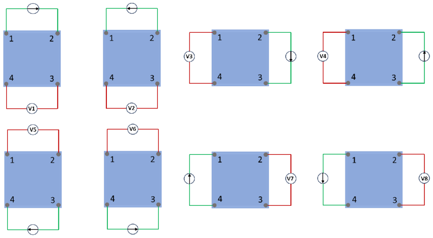
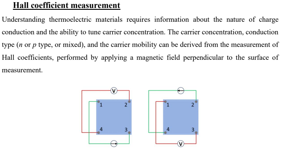
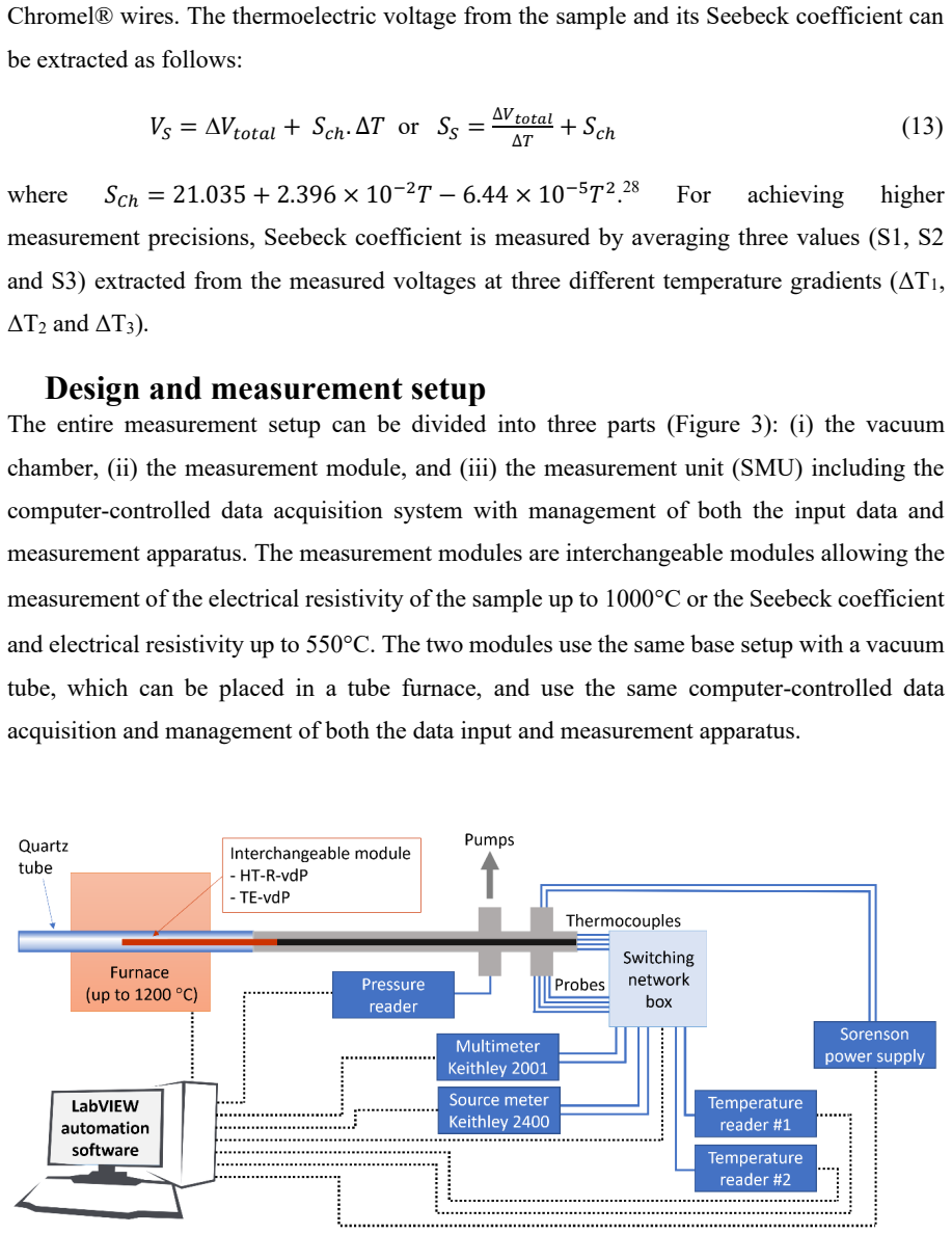
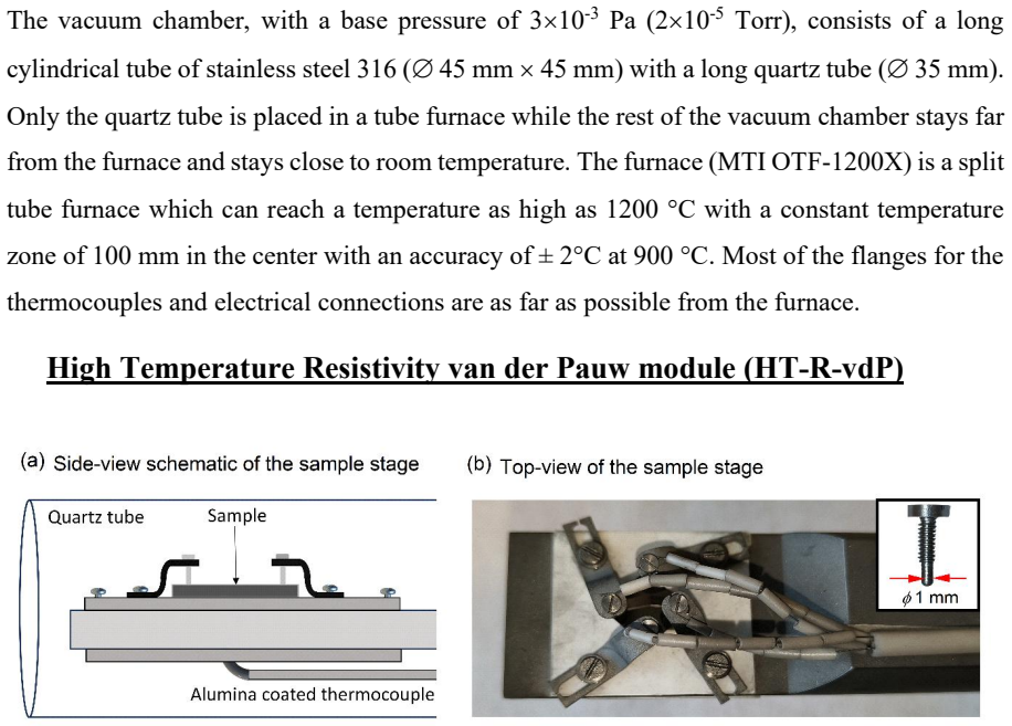
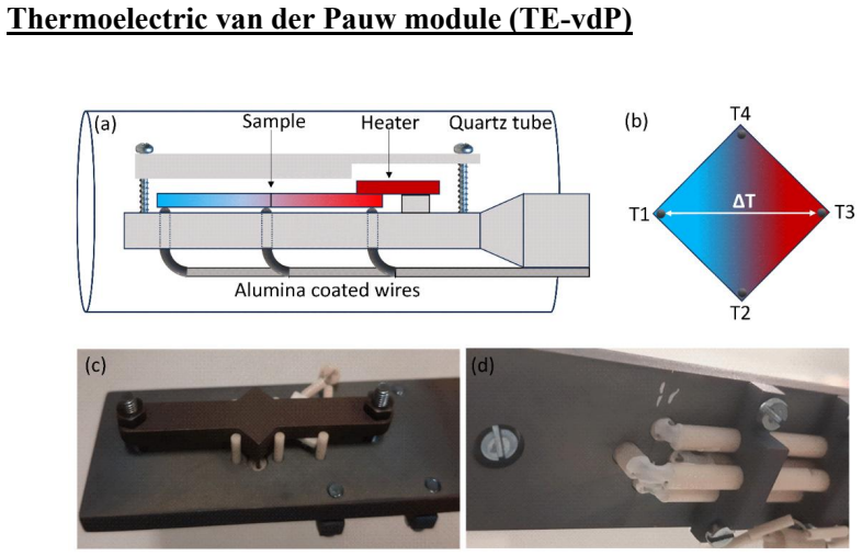
A modular thermoelectric properties measurement setup in van der Pauw configuration was developed for a straightforward and simultaneous measurement of electrical resistivity and Seebeck coefficient in an extensive temperature range of 25°C - 600°C and can also perform Hall measurements at room temperature. The setup is optimized for accurate measurement of voltages and temperature gradients by minimizing possible errors from offset voltages, wire contributions and thermal contact resistances which helps getting reliable data. The setup is user friendly, and the measurements are fully automated and controlled using a LabVIEW program. The detachable modules make this setup quite versatile and
What carries the argument
Modular setup in van der Pauw geometry that minimizes offset voltages, wire contributions, and thermal contact resistances during voltage and temperature gradient measurements.
If this is right
- Simultaneous measurement of electrical resistivity and Seebeck coefficient becomes possible in one platform.
- Data collection extends reliably across the full 25°C to 600°C range.
- Hall effect measurements are available at room temperature without separate equipment.
- Errors from offset voltages, wire contributions, and thermal contact resistances are reduced through the chosen configuration.
- Full automation via LabVIEW and detachable modules support versatile, user-friendly operation for multiple samples.
Where Pith is reading between the lines
- This single-platform approach could reduce the total number of instruments needed in a thermoelectric thin-film lab.
- The modular architecture leaves open the possibility of adding thermal-conductivity capability through a new detachable unit.
- Automated control may improve day-to-day reproducibility when screening many thin-film compositions.
- The design could be replicated in other labs to standardize high-temperature thermoelectric data collection.
Load-bearing premise
The modular design and specific choices for minimizing offset voltages, wire contributions, and thermal contact resistances actually produce reliable data across the stated temperature range.
What would settle it
A side-by-side comparison of resistivity and Seebeck coefficient values from this setup versus a calibrated commercial instrument on identical thin-film samples at multiple temperatures throughout 25-600°C would show large deviations if the error-minimization steps fail to deliver accuracy.
Figures
read the original abstract
A modular thermoelectric properties measurement setup in van der Pauw configuration was developed for a straightforward and simultaneous measurement of electrical resistivity and Seebeck coefficient in an extensive temperature range of 25{\deg}C - 600{\deg}C and can also perform Hall measurements at room temperature. The setup is optimized for accurate measurement of voltages and temperatures gradients by minimizing possible errors from offset voltages, wire contributions and thermal contact resistances which helps getting reliable data. The setup is user friendly, and the measurements are fully automated and controlled using a LabVIEW program. The detachable modules make this setup quite versatile and provide an all-in-one (except thermal conductivity) solution for thermoelectric measurements.
Editorial analysis
A structured set of objections, weighed in public.
Referee Report
Summary. The manuscript describes the design and construction of a modular van der Pauw geometry platform for simultaneous measurement of Seebeck coefficient and resistivity (25–600 °C) plus Hall effect (room temperature) on thin films. It details hardware choices intended to reduce offset voltages, wire contributions, and thermal contact resistances, together with LabVIEW automation and detachable modules for an all-in-one (except thermal conductivity) thermoelectric characterization tool.
Significance. A validated single-platform instrument of this type would reduce the need for multiple separate measurement systems and could improve throughput for thin-film thermoelectric studies. The manuscript supplies no calibration data, standard-sample comparisons, or temperature-dependent error budgets, so the practical significance of the design remains prospective rather than demonstrated.
major comments (1)
- [Abstract] Abstract and throughout: the central claim that the described error-minimization strategies (offset-voltage cancellation, wire-contribution reduction, thermal-contact control) produce reliable data across 25–600 °C is unsupported. No raw voltage/temperature traces, calibration runs, reference-sample comparisons, or quantified error budgets appear in the text.
Simulated Author's Rebuttal
We thank the referee for their constructive comments. We address the major comment on the lack of supporting data for the reliability claims below.
read point-by-point responses
-
Referee: [Abstract] Abstract and throughout: the central claim that the described error-minimization strategies (offset-voltage cancellation, wire-contribution reduction, thermal-contact control) produce reliable data across 25–600 °C is unsupported. No raw voltage/temperature traces, calibration runs, reference-sample comparisons, or quantified error budgets appear in the text.
Authors: We agree that the manuscript does not include calibration data, reference-sample comparisons, raw traces, or quantified error budgets, so the claim that the strategies produce reliable data is unsupported by presented evidence. The work centers on platform design, hardware choices, and automation rather than comprehensive validation. In revision we will add a results section with measurements on a standard thin-film sample (e.g., Bi2Te3 or constantan) over 25–600 °C, example raw voltage/temperature data, literature comparisons, and an estimated error budget. We will also revise the abstract and relevant text to state that the design aims to minimize errors for improved reliability, with validation shown in the results. revision: yes
Circularity Check
No circularity: purely descriptive apparatus paper with no derivations or predictions
full rationale
The manuscript describes a modular van der Pauw hardware setup and LabVIEW automation for resistivity, Seebeck, and Hall measurements. No equations, fitted parameters, predictions, or first-principles derivations appear in the text. The central claim is an engineering description of design choices for error minimization; reliability is asserted via hardware features rather than any mathematical reduction to prior results or self-citations. No load-bearing steps reduce by construction to inputs, satisfying the default expectation of zero circularity for non-theoretical papers.
Axiom & Free-Parameter Ledger
Reference graph
Works this paper leans on
-
[1]
1D. M. Rowe, CRC Handbook of Thermoelectrics (CRC Press). 2G. J. Snyder and E. S. Toberer Nature Materials 7, (2008). 3J. R. Sootsman, D. Y. Chung and M. G. Kanatzidis Angewandte Chemie International Edition 48, (2009). 4K. Behnia, Fundamentals of Thermoelectricity (Oxford University Press, 2015). 5J. P. Heremans and J. Martin Nature Materials 23, (2024)....
2008
-
[2]
Belliard, A
Fournier, L. Belliard, A. le Febvrier, C. Pallier and P. Eklund Journal of Physics D: Applied Physics 51, (2018). 34C. X. Quintela, F. Rivadulla and J. Rivas Applied Physics Letters 94, (2009). 35A. le Febvrier, S. K. Honnali, C. Poterie, T. V. Fernandes, R. Frost, V. Rogoz, M
2018
-
[3]
Giovannelli, J
Magnuson, F. Giovannelli, J. P. Leitão, J. F. Barbot and P. Eklund Journal of Materials Chemistry A 14, (2026)
2026
discussion (0)
Sign in with ORCID, Apple, or X to comment. Anyone can read and Pith papers without signing in.