Design Method of Quasi-Lumped Element Bandpass Filters Using Superconducting Coplanar Waveguide for Millimeter-Wave Multichroic Imaging
Pith reviewed 2026-06-30 04:28 UTC · model grok-4.3
The pith
Quasi-lumped element filters can be designed with elements sized up to a quarter wavelength for accurate 150-270 GHz bandpass performance in superconducting coplanar waveguide.
A machine-rendered reading of the paper's core claim, the machinery that carries it, and where it could break.
Core claim
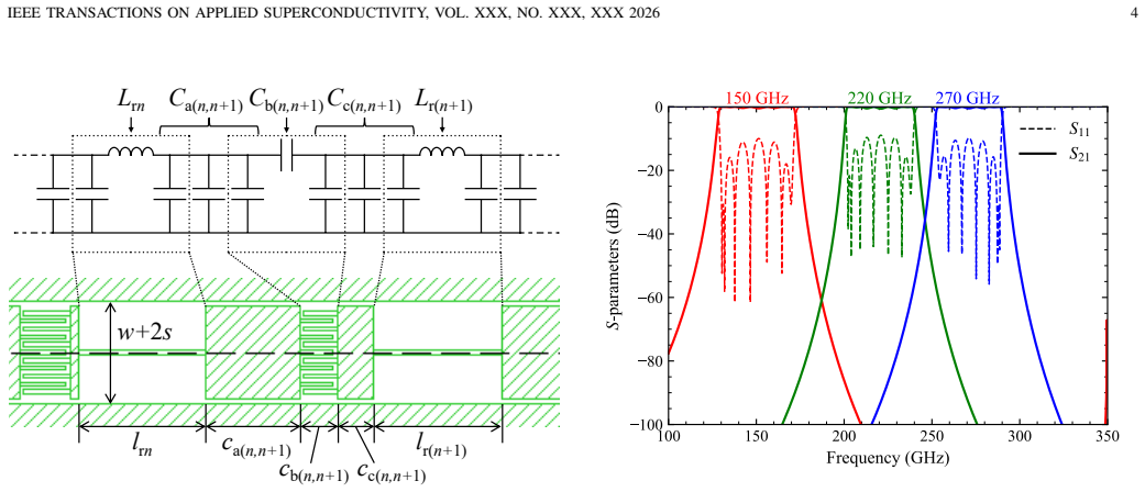
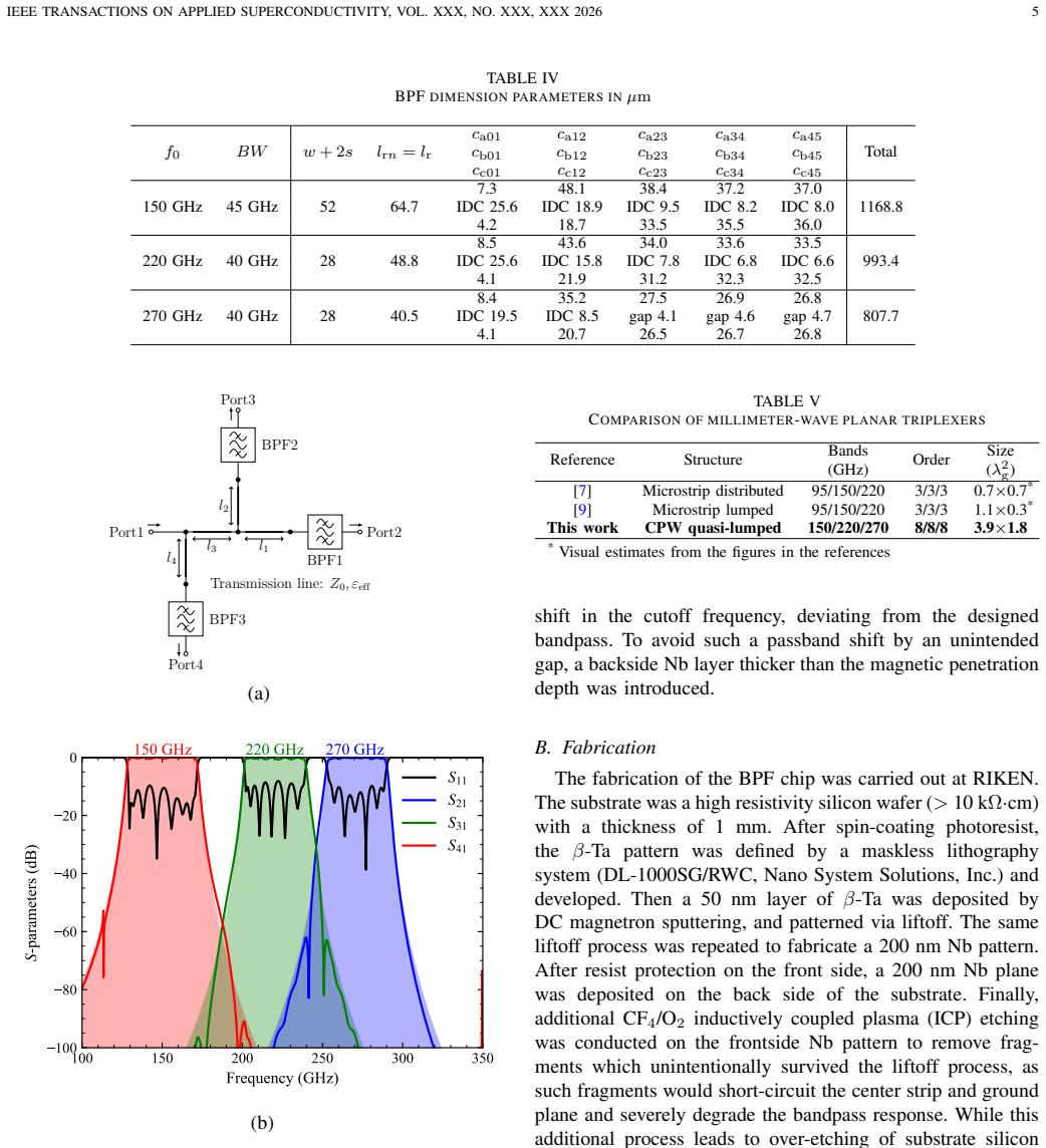
By defining a quasi-lumped element regime in which the largest circuit element reaches one-quarter wavelength, the authors obtain closed-form design solutions for 8th-order Chebyshev bandpass filters at 150, 220, and 270 GHz and for a triplexer, all realized in superconducting coplanar waveguide and shown to meet the inductance and capacitance values required after fabrication limits are applied.
What carries the argument
The quasi-lumped element approximation that treats circuit elements up to quarter-wavelength size as lumped for Chebyshev synthesis while retaining harmonic suppression.
If this is right
- Compact on-chip bandpass filters become feasible for 150, 220, and 270 GHz bands.
- An 8th-order triplexer can be realized on the same chip without excessive band-to-band crosstalk.
- Large-format detector arrays can incorporate these filters while keeping the overall pixel footprint small.
- Harmonic suppression from the quasi-lumped topology reduces the need for additional filtering stages.
Where Pith is reading between the lines
- The same sizing rule could be tested at higher frequencies where the quarter-wavelength limit becomes even more restrictive.
- Direct integration with transition-edge sensors or kinetic inductance detectors would test whether the filter footprint actually fits within a multichroic pixel.
- Electromagnetic simulation of the full triplexer layout would quantify any additional parasitic coupling not captured by the lumped model.
Load-bearing premise
Parasitic distributed effects remain small enough that the filter response and crosstalk levels stay close to the lumped-element prediction even when elements reach a quarter wavelength.
What would settle it
A measured S-parameter response of a fabricated 150 GHz filter that deviates from the target Chebyshev passband shape or shows higher than expected transmission in the harmonic bands.
Figures
read the original abstract
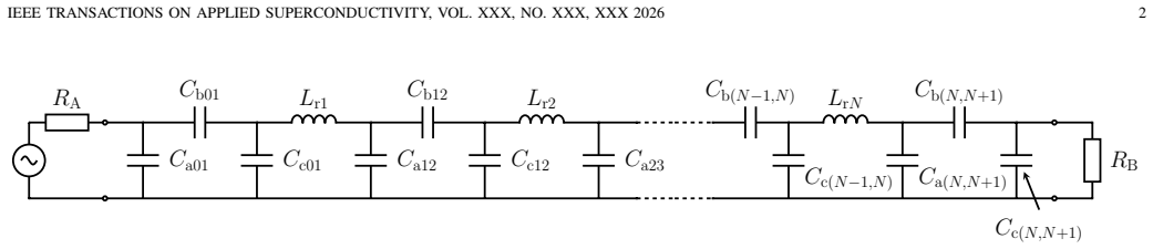
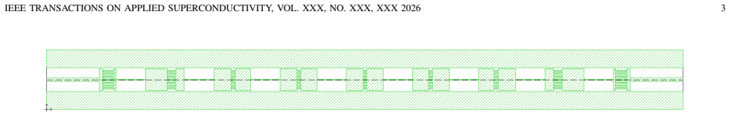
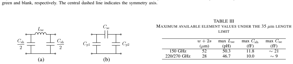
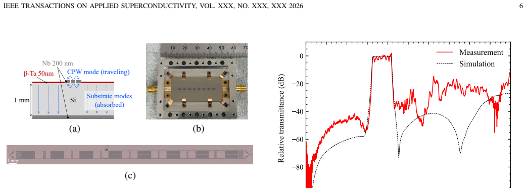
An on-chip band-defining filter coupled with a superconducting photon detector is a promising technology for developing multi-band imaging cameras at millimeter and submillimeter wavelengths. In this paper, we present the design of on-chip bandpass filters based on coplanar waveguide geometry, which can be easily integrated into large-format multi-band detector arrays. A lumped element filter design is suitable not only for achieving a compact footprint but also for suppressing harmonics to reduce band-to-band crosstalk in a multiplexer. However, the coplanar waveguide geometry and the photolithography process rule limit the maximum available inductance and capacitance of lumped elements, which does not sufficiently meet the requirements of filter circuits. To overcome this limitation, we have established a design method for quasi-lumped element filters, in which the maximum element size is relaxed to a quarter wavelength, exceeding the ideal lumped element size. We achieved design solutions for 150, 220, and 270 GHz 8th-order Chebyshev bandpass filters and a triplexer. We also report on the measurement results of a scaled model of the bandpass filter, demonstrating the validity of our proposed filter design.
Editorial analysis
A structured set of objections, weighed in public.
Referee Report
Summary. The manuscript presents a design method for quasi-lumped element bandpass filters in superconducting coplanar waveguide (CPW) geometry for millimeter-wave multichroic imaging. By relaxing the maximum element size limit to λ/4 (exceeding conventional lumped-element constraints imposed by photolithography), the authors derive 8th-order Chebyshev bandpass filter solutions at 150, 220, and 270 GHz together with a triplexer implementation. They report a scaled-model measurement to support the validity of the approach for on-chip integration with superconducting detectors.
Significance. If the quasi-lumped approximation remains accurate at the target frequencies, the method would enable more compact on-chip filters that satisfy fabrication limits while maintaining harmonic suppression and low crosstalk, directly benefiting large-format multichroic detector arrays in millimeter-wave astronomy. The explicit designs for three bands and a triplexer illustrate practical applicability, though the absence of quantitative metrics limits immediate assessment of performance gains over existing approaches.
major comments (2)
- [Abstract and measurement results] Abstract and measurement section: the claim of 'successful designs' and 'demonstrating the validity' is not supported by reported quantitative metrics such as measured insertion loss, return loss, fractional bandwidth deviation from Chebyshev targets, or direct simulation-to-measurement comparison for the scaled model; without these, the central assertion that the λ/4 relaxation meets filter specifications cannot be evaluated.
- [Design method and scaled-model measurement] Design method and validation: the quasi-lumped approximation (elements up to λ/4) is load-bearing for the 150–270 GHz designs, yet the scaled-model data are acquired at lower frequencies where kinetic inductance variation, distributed phase shift, and parasitic radiation are weaker; no section provides a quantitative error analysis or full-wave simulation confirming that these effects remain negligible at the design frequencies.
minor comments (2)
- [Abstract] The abstract would be strengthened by inclusion of at least one key performance number (e.g., achieved return loss or crosstalk level) from the scaled model.
- [Design method] Notation for the size-relaxation rule and the mapping from lumped to quasi-lumped element values should be defined explicitly with an equation or table to improve reproducibility.
Simulated Author's Rebuttal
We thank the referee for the constructive comments on our manuscript. We agree that strengthening the quantitative support for our claims will improve the paper and will revise accordingly. Below we respond point by point to the major comments.
read point-by-point responses
-
Referee: [Abstract and measurement results] Abstract and measurement section: the claim of 'successful designs' and 'demonstrating the validity' is not supported by reported quantitative metrics such as measured insertion loss, return loss, fractional bandwidth deviation from Chebyshev targets, or direct simulation-to-measurement comparison for the scaled model; without these, the central assertion that the λ/4 relaxation meets filter specifications cannot be evaluated.
Authors: We acknowledge that the abstract and measurement section do not currently include the specific quantitative metrics requested. In the revised manuscript we will add these values, including measured insertion loss and return loss at the scaled-model frequencies, the observed fractional bandwidth, its deviation from the target Chebyshev response, and direct overlay plots comparing measurement, electromagnetic simulation, and ideal lumped-element targets. These additions will allow readers to evaluate the performance of the λ/4-relaxed designs. revision: yes
-
Referee: [Design method and scaled-model measurement] Design method and validation: the quasi-lumped approximation (elements up to λ/4) is load-bearing for the 150–270 GHz designs, yet the scaled-model data are acquired at lower frequencies where kinetic inductance variation, distributed phase shift, and parasitic radiation are weaker; no section provides a quantitative error analysis or full-wave simulation confirming that these effects remain negligible at the design frequencies.
Authors: The referee is correct that the manuscript does not presently contain a quantitative error budget or full-wave simulations at the target frequencies. We will add a dedicated subsection that presents full-wave simulations of the 150/220/270 GHz filter layouts, quantifies the deviations caused by distributed effects, kinetic inductance, and radiation, and compares these to the quasi-lumped circuit model. This analysis will be performed at the design frequencies to demonstrate that the approximation remains within acceptable bounds for the intended application. revision: yes
Circularity Check
No significant circularity; design follows standard synthesis with independent validation
full rationale
The paper describes a design method extending standard 8th-order Chebyshev bandpass filter synthesis to allow element sizes up to λ/4 (quasi-lumped regime) for CPW geometry at 150-270 GHz, then reports achieving explicit designs for three bands plus a triplexer and validating via scaled-model measurements. No equations, parameters, or claims reduce the filter responses or crosstalk performance to quantities defined by the same data or by self-citation chains. The scaled-model results constitute external empirical support rather than a fitted input renamed as prediction. The derivation chain is therefore self-contained against external benchmarks (standard filter theory plus physical prototype data).
Axiom & Free-Parameter Ledger
free parameters (1)
- maximum element size limit
axioms (1)
- domain assumption Quasi-lumped element model remains valid when physical size reaches quarter wavelength at the design frequency
Reference graph
Works this paper leans on
-
[1]
The status of MUSIC: the multiwavelength sub- millimeter inductance camera,
J. Sayers, C. Bockstiegel, S. Brugger, N. G. Czakon, P. K. Day, T. P. Downes, R. P. Duan, J. Gao, A. K. Gill, J. Glenn, S. R. Golwala, M. I. Hollister, A. Lam, H. G. LeDuc, P. R. Maloney, B. A. Mazin, S. G. McHugh, D. A. Miller, A. K. Mroczkowski, O. Noroozian, H. T. Nguyen, J. A. Schlaerth, S. R. Siegel, A. Vayonakis, P. R. Wilson, and J. Zmuidzinas, “Th...
2014
-
[2]
The atacama cosmology telescope: The polarization-sensitive actpol instrument,
R. J. Thornton, P. A. R. Ade, S. Aiola, F. E. Angil `e, M. Amiri, J. A. Beall, D. T. Becker, H.-M. Cho, S. K. Choi, P. Corlies, K. P. Coughlin, R. Datta, M. J. Devlin, S. R. Dicker, R. D ¨unner, J. W. Fowler, A. E. Fox, P. A. Gallardo, J. Gao, E. Grace, M. Halpern, M. Hasselfield, S. W. Henderson, G. C. Hilton, A. D. Hincks, S. P. Ho, J. Hubmayr, K. D. Ir...
-
[3]
The POLARBEAR- 2 and Simons Array Focal Plane Fabrication Status,
B. Westbrook, P. A. R. Ade, M. Aguilar, Y . Akiba, K. Arnold, C. Bac- cigalupi, D. Barron, D. Beck, S. Beckman, A. N. Bender, F. Bianchini, D. Boettger, J. Borrill, S. Chapman, Y . Chinone, G. Coppi, K. Crowley, A. Cukierman, T. de Haan, R. D ¨unner, M. Dobbs, T. Elleflot, J. Errard, G. Fabbian, S. M. Feeney, C. Feng, G. Fuller, N. Galitzki, A. Gilbert, N...
2018
-
[4]
The design and integrated performance of spt-3g,
J. A. Sobrin, A. J. Anderson, A. N. Bender, B. A. Benson, D. Dutcher, A. Foster, N. Goeckner-Wald, J. Montgomery, A. Nadolski, A. Rahlin, P. A. R. Ade, Z. Ahmed, E. Anderes, M. Archipley, J. E. Austermann, J. S. Avva, K. Aylor, L. Balkenhol, P. S. Barry, R. B. Thakur, K. Benabed, F. Bianchini, L. E. Bleem, F. R. Bouchet, L. Bryant, K. Byrum, J. E. Carlstr...
-
[5]
The TolTEC camera: an overview of the instrument and in-lab testing results,
G. W. Wilson, S. Abi-Saad, P. Ade, I. Aretxaga, J. Austermann, Y . Ban, J. Bardin, J. Beall, M. Berthoud, S. Bryan, J. Bussan, E. Castillo, M. Chavez, R. Contente, N. S. DeNigris, B. Dober, M. Eiben, D. Fer- rusca, L. Fissel, J. Gao, J. E. Golec, R. Golina, A. Gomez, S. Gor- don, R. Gutermuth, G. Hilton, M. Hosseini, J. Hubmayr, D. Hughes, S. Kuczarski, D...
2020
-
[6]
Millimeter-wave lumped element superconducting band- pass filters for multi-color imaging,
S. Kumar, A. Vayonakis, H. G. LeDuc, P. K. Day, S. Golwala, and J. Zmuidzinas, “Millimeter-wave lumped element superconducting band- pass filters for multi-color imaging,”IEEE Transactions on Applied Superconductivity, vol. 19, no. 3, pp. 924–929, 2009
2009
-
[7]
Multi- chroic dual-polarization bolometric focal plane for studies of the cosmic microwave background,
A. Suzuki, K. Arnold, J. Edwards, G. Engargiola, A. Ghribi, W. Holzapfel, A. Lee, X. Meng, M. Myers, R. O’Brientet al., “Multi- chroic dual-polarization bolometric focal plane for studies of the cosmic microwave background,”Journal of Low Temperature Physics, vol. 167, no. 5, pp. 852–858, 2012
2012
-
[8]
A log-periodic focal-plane architecture for cosmic mi- crowave background polarimetry,
R. O’Brient, “A log-periodic focal-plane architecture for cosmic mi- crowave background polarimetry,” Ph.D. dissertation, University of California, Berkeley, 2010
2010
-
[9]
Multichroic bolometric detector architecture for cosmic microwave background polarimetry experiments,
A. Suzuki, “Multichroic bolometric detector architecture for cosmic microwave background polarimetry experiments,” Ph.D. dissertation, University of California, Berkeley, 2013
2013
-
[10]
350-ghz bandpass filters using superconducting coplanar waveguide,
J.-Q. Ding, J. Hu, and S.-C. Shi, “350-ghz bandpass filters using superconducting coplanar waveguide,”IEEE Transactions on Terahertz Science and Technology, vol. 11, no. 5, pp. 548–556, 2021
2021
-
[11]
Wideband multichroic detector architecture for millimeter and submillimeter imaging observations,
S. Uno, “Wideband multichroic detector architecture for millimeter and submillimeter imaging observations,” Ph.D. dissertation, The University of Tokyo, 2024
2024
-
[12]
Study on design of microstrip lumped-element bandpass filters,
K. Nomura and Y . Kobayashi, “Study on design of microstrip lumped-element bandpass filters,”IEICE Technical Report, MW96- 84, pp. 19–24, 1996. [Online]. Available: https://cir.nii.ac.jp/crid/ 1571417124446213120
1996
-
[13]
Matthaei, L
G. Matthaei, L. Young, and E. Jones,Microwave Filters, Impedance- matching Networks, and Coupling Structures. Artech House, 1980
1980
-
[14]
D. M. Pozar,Microwave engineering. John wiley & sons, 2011
2011
-
[15]
Sonnet Version 18.56,
Sonnet Software, Inc., “Sonnet Version 18.56,” https://www. sonnetsoftware.com
-
[16]
Coplanar waveguide circuits, components, and systems,
R. N. Simons, “Coplanar waveguide circuits, components, and systems,” Wiley Series in Microwave and Optical Engineering, 2001
2001
-
[17]
Design of manifold-coupled multiplexers,
R. I. Cameron and M. Yu, “Design of manifold-coupled multiplexers,” IEEE Microwave Magazine, vol. 8, no. 5, pp. 46–59, 2007
2007
-
[18]
HFSS, Ansys Electronics Desktop 2022 R1,
Ansys, Inc., “HFSS, Ansys Electronics Desktop 2022 R1,” https://www. ansys.com/products/electronics/ansys-hfss
2022
discussion (0)
Sign in with ORCID, Apple, or X to comment. Anyone can read and Pith papers without signing in.