Investigation and Mitigation of a Prominent Off-Axis Stray Light Path in Rubin Observatory Commissioning
Pith reviewed 2026-07-01 02:47 UTC · model grok-4.3
The pith
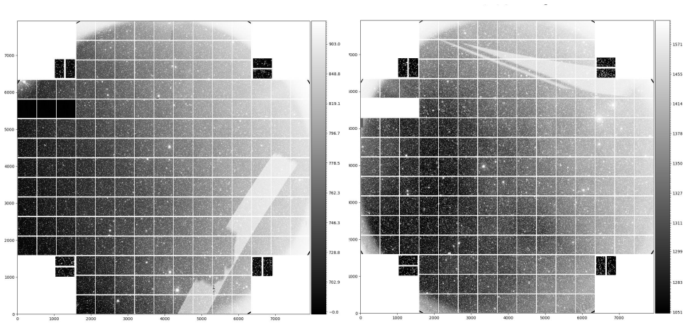
Light from large off-axis angles passes between light baffles, reflects off the primary mirror, and creates the scratched tape feature on the LSST Camera focal plane.
A machine-rendered reading of the paper's core claim, the machinery that carries it, and where it could break.
Core claim
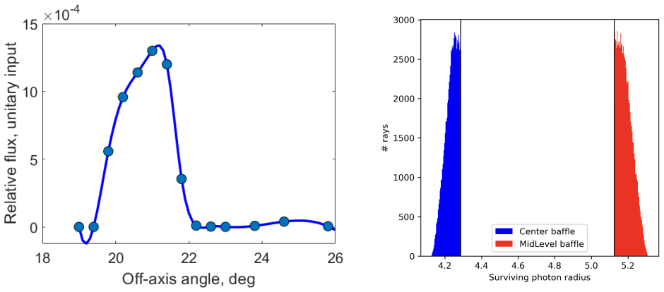
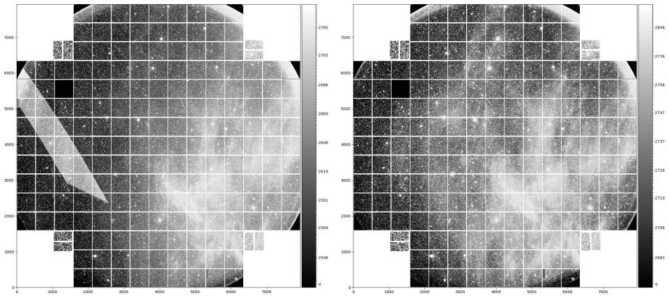
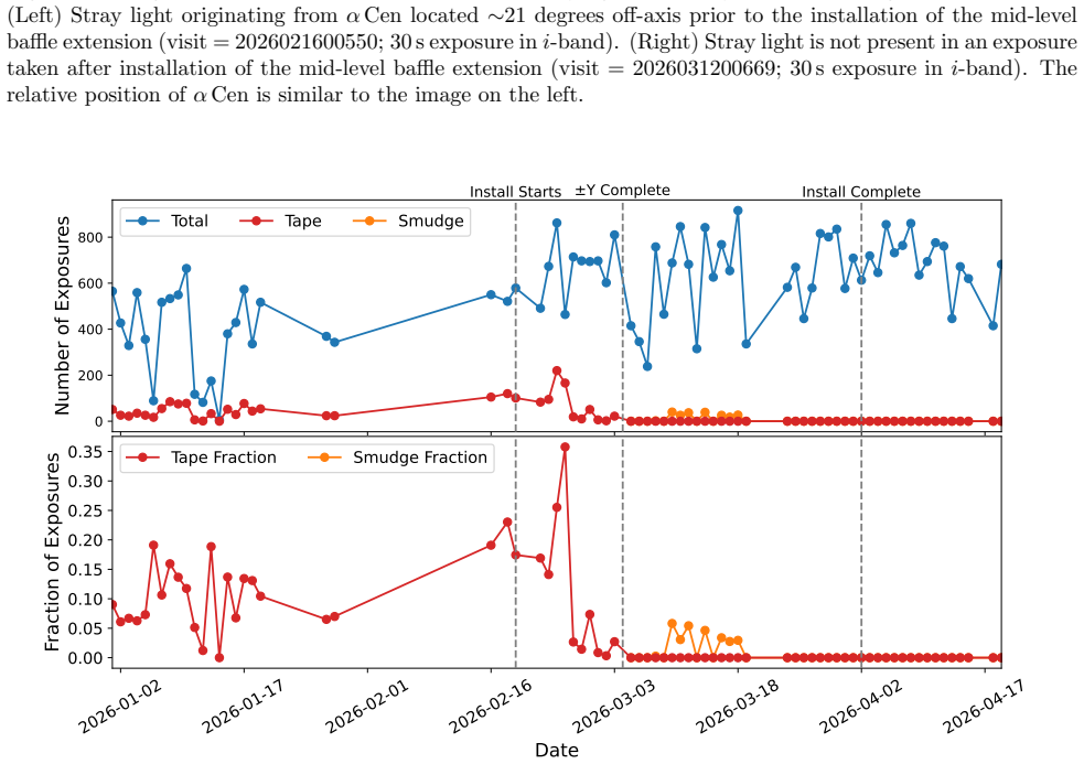
The scratched tape stray light feature originates when light from large off-axis angles (~20 deg) passes between the mid-level and center-section light baffles, reflects off the primary mirror, and illuminates the LSST Camera focal plane. This scenario represented an unobstructed stray light path to the sky during Rubin commissioning due to delays in the integration of the dome slit light-wind screen.
What carries the argument
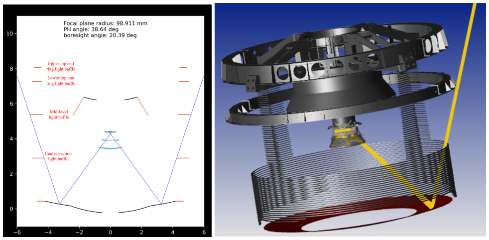
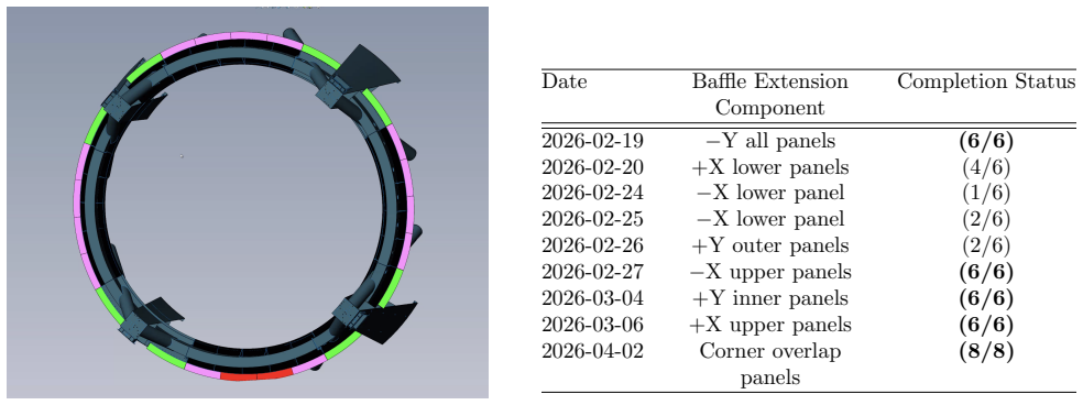
The gap between the mid-level and center-section light baffles that permits off-axis light to reach the primary mirror and then the focal plane.
Load-bearing premise
The delays in the integration of the dome slit light-wind screen left an unobstructed stray light path to the sky during commissioning.
What would settle it
An observation or ray-trace calculation showing that the scratched tape pattern on the focal plane does not match the illumination expected from 20-degree off-axis light reflected off the primary mirror, or that the feature persists after the wind screen is installed.
Figures
read the original abstract
The "scratched tape" stray light feature is the most prominent and prevalent stray light artifact identified during the commissioning of the Vera C. Rubin Observatory. The scratched tape feature originates when light from large off-axis angles (~20 deg) passes between the mid-level and center-section light baffles, reflects off the primary mirror, and illuminates the LSST Camera focal plane. This scenario represented an unobstructed stray light path to the sky during Rubin commissioning due to delays in the integration of the dome slit light-wind screen. This document describes the identification, modeling, characterization, and mitigation of the scratched tape stray light artifact.
Editorial analysis
A structured set of objections, weighed in public.
Referee Report
Summary. The manuscript identifies the origin of the prominent 'scratched tape' stray light artifact observed in LSST Camera data during Rubin Observatory commissioning. It attributes the feature to light incident at large off-axis angles (~20 deg) that passes between the mid-level and center-section light baffles, reflects from the primary mirror, and reaches the focal plane. This path existed because of delays in integrating the dome slit light-wind screen. The paper describes the identification process, ray-tracing modeling of the geometry, on-sky characterization, and the mitigation steps implemented.
Significance. The work addresses a concrete operational issue that affected commissioning data quality for a major survey facility. Successful diagnosis and mitigation of a specific stray-light path via physical modeling and hardware intervention provides a useful case study for stray-light control in large-aperture telescopes. The emphasis on commissioning timeline context and practical fixes is a strength.
major comments (1)
- [Abstract / Characterization] Abstract and characterization description: the claim that modeling and characterization were performed is not supported by any quantitative validation, error analysis, before-after intensity metrics, or statistical comparison of stray-light levels. This absence weakens the central assertion that the identified path was both the dominant source and successfully mitigated.
Simulated Author's Rebuttal
We thank the referee for their constructive review and positive assessment of the work's significance. We address the single major comment below.
read point-by-point responses
-
Referee: [Abstract / Characterization] Abstract and characterization description: the claim that modeling and characterization were performed is not supported by any quantitative validation, error analysis, before-after intensity metrics, or statistical comparison of stray-light levels. This absence weakens the central assertion that the identified path was both the dominant source and successfully mitigated.
Authors: We agree that the manuscript would be strengthened by explicit quantitative validation. The current text describes the ray-tracing geometry, on-sky identification, and mitigation timeline but does not include error budgets, intensity metrics, or statistical before-after comparisons. In the revised manuscript we will add a dedicated subsection with (i) quantitative ray-tracing validation against measured artifact positions and intensities, (ii) before-and-after stray-light level measurements extracted from commissioning exposures, and (iii) a simple statistical comparison of the artifact amplitude pre- and post-installation of the dome slit light-wind screen. These additions will directly support the claims of dominance and successful mitigation. revision: yes
Circularity Check
No significant circularity detected
full rationale
The manuscript identifies a stray-light path via ray-tracing of the known Rubin telescope geometry, on-sky characterization, and mitigation steps. The central claim rests on physical description of baffle geometry and the factual commissioning timeline regarding the absent light-wind screen; neither is derived from fitted parameters, self-referential equations, nor load-bearing self-citations. No derivation chain reduces to its own inputs by construction, and the argument is self-contained against external geometric and observational benchmarks.
Axiom & Free-Parameter Ledger
Reference graph
Works this paper leans on
-
[1]
LSST: From Science Drivers to Reference Design and Antici- pated Data Products,
Ivezi´ c,ˇZ., Kahn, S. M., Tyson, J. A., et al., “LSST: From Science Drivers to Reference Design and Antici- pated Data Products,” ApJ873(2), 111 (2019)
2019
-
[2]
Rubin Observatory rotating enclosure (dome) progress and status,
Marchiori, G., De Lorenzi, S., Martinez, J., et al., “Rubin Observatory rotating enclosure (dome) progress and status,” in [Ground-based and Airborne Telescopes X], Marshall, H. K., Spyromilio, J., and Usuda, T., eds.,Society of Photo-Optical Instrumentation Engineers (SPIE) Conference Series13094, 1309404 (2024)
2024
-
[3]
An Overview of the Stray Light Findings and Interpretation During the LSSTCam Commissioning On-sky,
Rodeghiero, G., Drlica-Wagner, A., Taranto, A., et al., “An Overview of the Stray Light Findings and Interpretation During the LSSTCam Commissioning On-sky,” in [to be published in Ground-based and Airborne Telescopes XI],Society of Photo-Optical Instrumentation Engineers (SPIE) Conference Series 14147, 14147146 (2026)
2026
-
[4]
Investigation of the Scratched Tape Scattered Light Artifact at Rubin Observatory,
Drlica-Wagner, A., Taranto, A., Rodeghiero, G., et al., “Investigation of the Scratched Tape Scattered Light Artifact at Rubin Observatory,” Commissioning Technical Note SITCOMTN-166, Vera C. Rubin Observatory (2025).https://sitcomtn-166.lsst.io
2025
-
[5]
Rubin Observatory Simonyi Survey Telescope status overview,
Thomas, S. J., Barr, J., Callahan, S., et al., “Rubin Observatory Simonyi Survey Telescope status overview,” in [Ground-based and Airborne Telescopes IX], Marshall, H. K., Spyromilio, J., and Usuda, T., eds.,Society of Photo-Optical Instrumentation Engineers (SPIE) Conference Series12182, 121820W (2022)
2022
-
[6]
and Jaschek, C., [The Bright Star Catalogue], 4th ed
Hoffleit, D. and Jaschek, C., [The Bright Star Catalogue], 4th ed. (1982)
1982
-
[7]
Optical Assemblies and Light Baffles Mount Location Drawings,
Neill, D. R., “Optical Assemblies and Light Baffles Mount Location Drawings,” Telescope & Site Controlled Document LTS-213, Vera C. Rubin Observatory (2013).https://ls.st/LTS-213
2013
-
[8]
A collimated beam projector for precise telescope calibration,
Coughlin, M., Abbott, T. M. C., Brannon, K., et al., “A collimated beam projector for precise telescope calibration,” in [Observatory Operations: Strategies, Processes, and Systems VI], Peck, A. B., Seaman, R. L., and Benn, C. R., eds.,Society of Photo-Optical Instrumentation Engineers (SPIE) Conference Series 9910, 99100V (2016)
2016
-
[9]
Measurement of Telescope Transmission Using a Collimated Beam Projector,
Mondrik, N., Coughlin, M., Betoule, M., Bongard, S., Rice, J. P., Shaw, P.-S., Stubbs, C. W., Woodward, J. T., and LSST Dark Energy Science Collaboration, “Measurement of Telescope Transmission Using a Collimated Beam Projector,” PASP135(1045), 035001 (2023)
2023
-
[10]
Collimated Beam Projector Installation and ComCam Testing,
Urbach, E. K., Fagrelius, P., Mueller, F., and Amouroux, N., “Collimated Beam Projector Installation and ComCam Testing,” Commissioning Technical Note SITCOMTN-152, Vera C. Rubin Observatory (2025). https://sitcomtn-152.lsst.io
2025
-
[11]
batoid: A C++ Backed Python Optical Raytracer,
Meyers, J. E., Kirkby, D., and Thomas, D., “batoid: A C++ Backed Python Optical Raytracer,” (2019). https://github.com/jmeyers314/batoid
2019
-
[12]
Ansys Zemax OpticStudio,
Ansys, Inc., “Ansys Zemax OpticStudio,” (2024).https://www.ansys.com/products/optics/ ansys-zemax-opticstudio
2024
-
[13]
Calculating LSST limiting magnitudes and SNR,
Jones, L., “Calculating LSST limiting magnitudes and SNR,” Simulations Team Technical Note SMTN-002, Vera C. Rubin Observatory (2022).https://smtn-002.lsst.io
2022
discussion (0)
Sign in with ORCID, Apple, or X to comment. Anyone can read and Pith papers without signing in.