Simulation Credibility Assessment Methodology with FPGA-based Hardware-in-the-loop Platform
Pith reviewed 2026-05-25 00:30 UTC · model grok-4.3
The pith
FPGA simulation of sensor chips keeps the hardware and software environment identical between simulation and real experiments.
A machine-rendered reading of the paper's core claim, the machinery that carries it, and where it could break.
Core claim
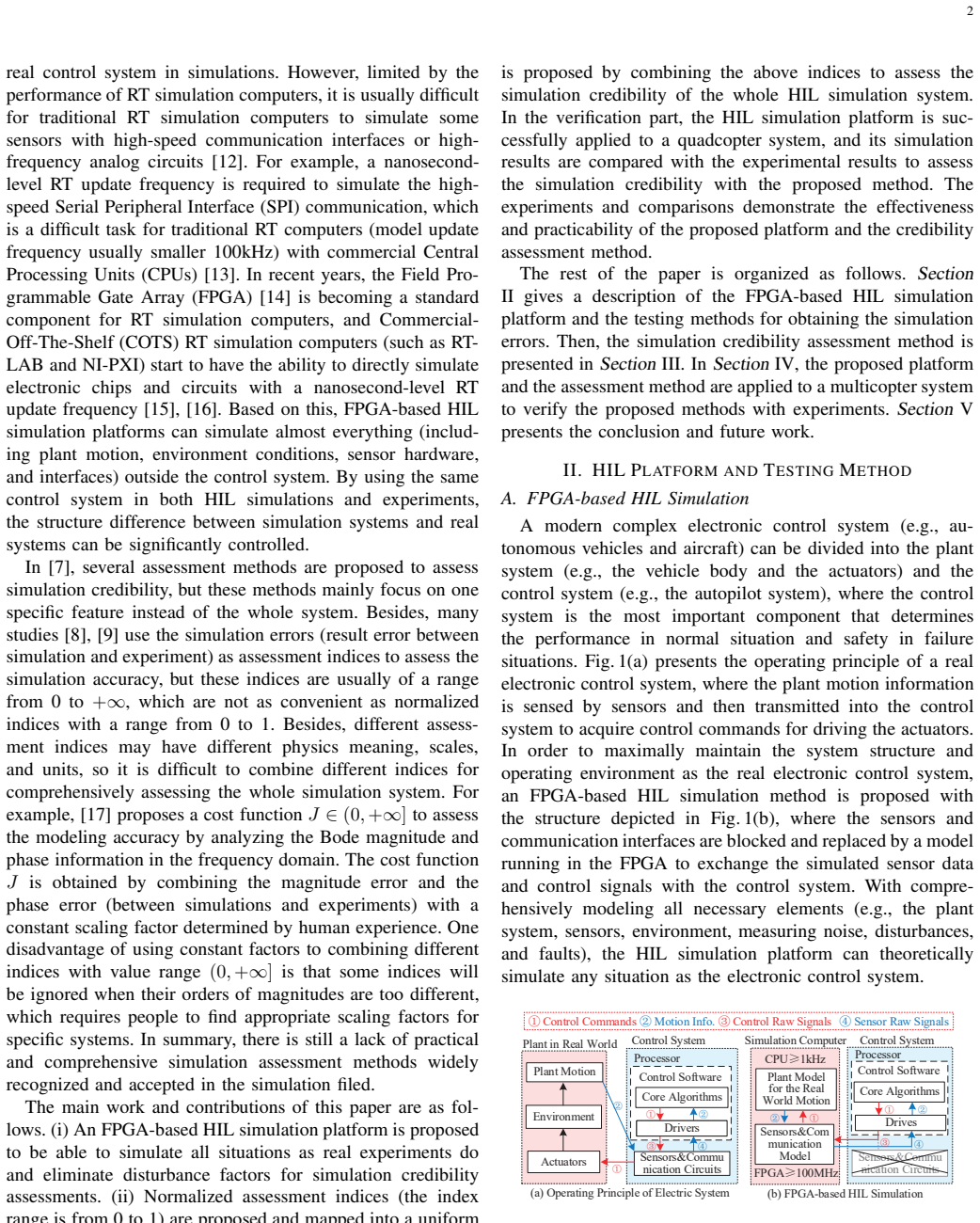
By using the FPGA to simulate all sensor chips, the simulation platform can ensure that the tested electronic system maintains the same hardware and software operating environment in both simulations and experiments, which makes it possible to perform the same tests in the simulation platform and the real experiment to compare and analyze the simulation errors. Testing methods and normalized assessment indices from performance, time-domain, and frequency-domain perspectives are then combined into an overall credibility index for the platform.
What carries the argument
FPGA emulation of all sensor chips so that the controller hardware and software see identical interfaces and timing in simulation and experiment.
If this is right
- Identical test sequences become feasible in simulation and experiment, allowing direct subtraction of results to isolate simulation error.
- Normalized indices from different domains can be compared and summed without unit conversion.
- An overall credibility score is produced that reflects the platform's fidelity across all tested aspects.
- The same platform and indices can be reused on any electronic control system whose sensors can be emulated on FPGA.
Where Pith is reading between the lines
- The approach could be used to decide when a simulation model is accurate enough to replace some physical tests during development.
- Discrepancies found by the method could guide targeted improvements to sensor models rather than wholesale model replacement.
- The normalized 0-1 scale might serve as a common currency for comparing credibility across simulation platforms built by different teams.
Load-bearing premise
Accurately emulating each sensor chip individually on the FPGA is sufficient to reproduce the complete system-level interactions and timing present in the physical hardware.
What would settle it
A measurable difference in timing or closed-loop behavior between the FPGA-simulated sensors and the physical sensors when the identical controller software runs the same command sequence on both.
Figures


read the original abstract
Electronic control systems are becoming more and more complicated, which makes it difficult to test them sufficiently only through experiments. Simulation is an efficient way in the development and testing of complex electronic systems, but the simulation results are always doubtful by people due to the lack of credible simulation platforms and assessment methods. This paper proposes a credible simulation platform based on real-time FPGA-based hardware-in-the-loop (HIL) simulation, and then an assessment method is proposed to quantitatively assess its simulation credibility. By using the FPGA to simulate all sensor chips, the simulation platform can ensure that the tested electronic system maintains the same hardware and software operating environment in both simulations and experiments, which makes it possible to perform the same tests in the simulation platform and the real experiment to compare and analyze the simulation errors. Then, the testing methods and assessment indices are proposed to assess the simulation platform from various perspectives, such as performance, time-domain response, and frequency-domain response. These indices are all normalized to the same scale (from 0 to 1) and mapped to a uniform assessment criterion, which makes it convenient to compare and synthesize different assessment indices. Finally, an overall assessment index is proposed by combining all assessment indices obtained from different tests to assess the simulation credibility of the whole simulation platform. The simulation platform and the proposed assessment method are applied to a multicopter system, where the effectiveness and practicability are verified by simulations and experiments.
Editorial analysis
A structured set of objections, weighed in public.
Referee Report
Summary. The paper proposes an FPGA-based real-time hardware-in-the-loop (HIL) simulation platform that emulates all sensor chips to maintain identical hardware and software operating environments between simulation and physical experiments on electronic control systems. It defines a set of normalized assessment indices (scaled 0-1) covering performance, time-domain response, and frequency-domain response, combines them into an overall credibility index, and demonstrates the platform and method on a multicopter system via simulations and experiments.
Significance. If the environment-equivalence claim holds and the indices prove robust under validation, the work could supply a concrete, comparable framework for quantifying HIL simulation credibility—an area where current practice often relies on ad-hoc checks. The explicit normalization to a common scale and the multicopter case study are practical strengths that would aid adoption if the core assumptions are substantiated.
major comments (1)
- [Section 3 and multicopter case study] Section 3 and multicopter case study: the central claim that the FPGA platform enables direct, apples-to-apples simulation-vs-experiment error comparison rests on the assertion that emulating individual sensor chips produces an operating environment identical to physical hardware. No explicit validation (e.g., timing diagrams, protocol traces, or electrical-characteristic measurements) is supplied showing that FPGA models reproduce bus timing, noise, power, or interface behavior without introducing new artifacts; any systematic mismatch would invalidate the error-comparison premise and the resulting credibility indices.
minor comments (2)
- [Abstract] The abstract states that indices are 'normalized to the same scale (from 0 to 1)' and mapped to a uniform criterion, yet the manuscript should supply the explicit normalization formulas and the weighting/synthesis rule for the overall index in the main text rather than deferring all detail to later sections.
- [Figures and tables] Figure captions and table headings should explicitly state the number of experimental runs and the statistical treatment (e.g., mean ± std) used to compute each index so that reproducibility is immediate.
Simulated Author's Rebuttal
We thank the referee for the constructive feedback. We address the single major comment below.
read point-by-point responses
-
Referee: [Section 3 and multicopter case study] Section 3 and multicopter case study: the central claim that the FPGA platform enables direct, apples-to-apples simulation-vs-experiment error comparison rests on the assertion that emulating individual sensor chips produces an operating environment identical to physical hardware. No explicit validation (e.g., timing diagrams, protocol traces, or electrical-characteristic measurements) is supplied showing that FPGA models reproduce bus timing, noise, power, or interface behavior without introducing new artifacts; any systematic mismatch would invalidate the error-comparison premise and the resulting credibility indices.
Authors: We agree that the manuscript's central claim would be strengthened by explicit validation of the FPGA sensor emulation. The submission describes emulation of individual sensor chips to maintain identical hardware-software environments but does not include supporting measurements such as timing diagrams, protocol traces, or electrical-characteristic comparisons. In the revised version we will add these data in Section 3 to demonstrate that bus timing, interface behavior, and other relevant characteristics are reproduced without introducing new systematic artifacts. This addition will directly support the premise underlying the normalized assessment indices and the multicopter demonstration. revision: yes
Circularity Check
No circularity; assessment indices are independent comparisons
full rationale
The paper defines a simulation platform by FPGA sensor emulation and then proposes normalized indices (performance, time/frequency domain) computed directly from paired simulation-vs-experiment runs on the same tests. These indices are combined into an overall score by explicit averaging or mapping; none is defined in terms of itself or obtained by fitting parameters to the target credibility quantity. No self-citations are invoked as uniqueness theorems or load-bearing premises. The derivation chain is therefore self-contained against external benchmarks.
Axiom & Free-Parameter Ledger
axioms (1)
- domain assumption FPGA simulation of individual sensor chips produces system-level timing and interaction behavior equivalent to physical hardware
Reference graph
Works this paper leans on
-
[1]
A 400-V/50-kV A digital-physical hybrid real-time simulation platform for power systems,
C. Mao, F. Leng, J. Li, S. Zhang, L. Zhang, R. Mo, D. Wang, J. Zeng, X. Chen, R. An, and Y . Zhao, “A 400-V/50-kV A digital-physical hybrid real-time simulation platform for power systems,” IEEE Transactions on Industrial Electronics, vol. 65, no. 5, pp. 3666–3676, 2018
work page 2018
-
[2]
A m atrix- inversion technique for FPGA-based real-time emt simulati on of power converters,
A. Hadizadeh, M. Hashemi, M. Labbaf, and M. Parniani, “A m atrix- inversion technique for FPGA-based real-time emt simulati on of power converters,” IEEE Transactions on Industrial Electronics , vol. 66, no. 2, pp. 1224–1234, 2019
work page 2019
-
[3]
C. Qi, F. Gao, X. Zhao, A. Ren, and Q. Wang, “A force compens ation approach toward divergence of hardware-in-the-loop conta ct simulation system for damped elastic contact,” IEEE Transactions on Industrial Electronics, vol. 64, no. 4, pp. 2933–2943, 2017
work page 2017
-
[4]
Y . Chen, S. Chen, T. Zhang, S. Zhang, and N. Zheng, “Autono mous vehicle testing and validation platform: Integrated simul ation system with hardware in the loop,” in 2018 IEEE Intelligent V ehicles Symposium (IV), 2018, pp. 949–956
work page 2018
-
[5]
I. Tejado, J. Serrano, E. P´ erez, D. Torres, and B. M. Vina gre, “Low-cost hardware-in-the-loop testbed of a mobile robot to support l earning in automatic control and robotics,” IF AC-PapersOnLine, vol. 49, no. 6, pp. 242–247, 2016
work page 2016
-
[6]
A practical perform ance evaluation method for electric multicopters,
D. Shi, X. Dai, X. Zhang, and Q. Quan, “A practical perform ance evaluation method for electric multicopters,” IEEE/ASME Transactions on Mechatronics, vol. 22, no. 3, pp. 1337–1348, 2017
work page 2017
-
[7]
Simulation credibility: Advances in verification, v alidation, and uncertainty quantification,
U. B. Mehta, D. R. Eklund, V . J. Romero, J. A. Pearce, and N. S. Keim, “Simulation credibility: Advances in verification, v alidation, and uncertainty quantification,” NASA Ames Research Center, Mo ffett Field, CA United States, Tech. Rep. JANNAF/GL-2016-0001, Nov. 01, 2016
work page 2016
-
[8]
X. H. Mai, S. K. Kwak, J. H. Jung, and K. A. Kim, “Comprehens ive electric-thermal photovoltaic modeling for power-hardwa re-in-the-loop simulation (PHILS) applications,” IEEE Transactions on Industrial Electronics, vol. 64, no. 8, pp. 6255–6264, 2017
work page 2017
-
[9]
T. Roinila, T. Messo, R. Luhtala, R. Scharrenberg, E. C. D e Jong, A. Fabian, and Y . Sun, “Hardware-in-the-loop methods for re al-time frequency-response measurements of on-board power distri bution sys- tems,” IEEE Transactions on Industrial Electronics , vol. 66, no. 7, pp. 5769–5777, 2019
work page 2019
-
[10]
History of verification and v alidation of simulation models,
R. G. Sargent and O. Balci, “History of verification and v alidation of simulation models,” in Proceedings of the 2017 Winter Simulation Conference, ser. WSC ’17. Piscataway, NJ, USA: IEEE Press, 2017, pp. 1–16
work page 2017
-
[11]
Assessing computational model credibility using a risk- based framework,
T. M. Morrison, P . Hariharan, C. M. Funkhouser, P . Afsha ri, M. Goodin, and M. Horner, “Assessing computational model credibility using a risk- based framework,” ASAIO Journal , no. 4, pp. 349–360
-
[12]
O. Lucia, I. Urriza, L. A. Barragan, D. Navarro, O. Jimen ez, and J. M. Burdio, “Real-time FPGA-based hardware-in-the-loop simu lation test bench applied to multiple-output power converters,” IEEE Transactions on Industry Applications , vol. 47, no. 2, pp. 853–860, 2010
work page 2010
-
[13]
Real-time simulation of MMCs using CPU and FPGA ,
H. Saad, T. Ould-Bachir, J. Mahseredjian, C. Dufour, S. Dennetiere, and S. Nguefeu, “Real-time simulation of MMCs using CPU and FPGA ,” IEEE Transactions on Power Electronics , vol. 30, no. 1, pp. 259–267, 2015
work page 2015
-
[14]
M. Matar and R. Iravani, “FPGA implementation of the pow er electronic converter model for real-time simulation of electromagnet ic transients,” IEEE Transactions on Power Delivery, vol. 25, no. 2, pp. 852–860, 2010
work page 2010
-
[15]
S. Mikkili, A. K. Panda, and J. Prattipati, “Review of re al-time simulator and the steps involved for implementation of a model from MA T - LAB/SIMULINK to real-time,” Journal of The Institution of Engineers (India): Series B , vol. 96, no. 2, pp. 179–196, 2015
work page 2015
-
[16]
S. S. Noureen, V . Roy, and S. B. Bayne, “An overall study o f a real- time simulator and application of RT-LAB using MA TLAB simpo wer- systems,” in 2017 IEEE Green Energy and Smart Systems Conference , 2018, pp. 1–5
work page 2017
-
[17]
R. K. Remple and M. B. Tischler, Aircraft and rotorcraft system identification: engineering methods with flight-test examp les. American Institute of Aeronautics and Astronautics, 2006
work page 2006
-
[18]
Quan, Introduction to Multicopter Design and Control
Q. Quan, Introduction to Multicopter Design and Control . Springer, Singapore, 2017
work page 2017
-
[19]
B. L. Stevens and F. L. Lewis, Aircraft Control and Simulation 2nd Edition. Wiley, New Jersey, 2004
work page 2004
-
[20]
Quadcopter flight simulation model - mam bo,
I. MathWorks, “Quadcopter flight simulation model - mam bo,” https://ww2.mathworks.cn/help/aeroblks/quadcopter-project.html, Accessed April 17, 2019
work page 2019
-
[21]
X. Dai, Q. Quan, J. Ren, and K.-Y . Cai, “An analytical des ign optimization method for electric propulsion systems of mul ticopter UA Vs with desired hovering endurance,” IEEE/ASME Transactions on Mechatronics, vol. 24, no. 1, pp. 228–239, 2019
work page 2019
-
[22]
Efficiency opti mization and component selection for propulsion systems of electric mul ticopters,
X. Dai, Q. Quan, J. Ren, and C. Kai-Y uan, “Efficiency opti mization and component selection for propulsion systems of electric mul ticopters,” IEEE Transactions on Industrial Electronics , vol. 66, no. 10, pp. 7800– 7809, 2019
work page 2019
discussion (0)
Sign in with ORCID, Apple, or X to comment. Anyone can read and Pith papers without signing in.