REVIEW 3 major objections 4 minor 31 references
Directional Measurements in Urban Street Canyons from Macro Rooftop Sites at 28 GHz for 90% Outdoor Coverage
T0 review · 3 major / 4 minor · reviewed 2026-08-14 · deepseek-v4-flash
Pith's one-line read This paper establishes an empirical 28 GHz path-gain law for rooftop base stations serving street-level terminals, including a 15 dB penalty when the antenna is set back from the roof edge, and shows that high-gain antennas retain nearly…
desk verdict Large, careful 28 GHz street-canyon measurement campaign with useful empirical models; the absolute values lean on a lightly documented antenna-calibration assumption that the authors should pin down before it is cited as gospel. read the letter →
The pith
A machine-rendered reading of the paper's core claim, the machinery that carries it, and where it could break.
The reading
What carries the argument
The measurement core is a rotating 10-degree receive horn (24 dBi) at rooftop height that takes full 360-degree azimuth power scans while a street-level transmitter emits a 28 GHz continuous wave. The load-bearing identity is that the azimuthal average of received power equals the average omnidirectional power, a derivation taken from the authors' earlier corridor work; subtracting transmit power and nominal gains converts that average into an omnidirectional path gain. The modeling core is a slope-intercept path-gain fit in log-distance, plus a diffraction-inspired around-corner formula in which the corner acts as a re-radiating source with an empirical corner-loss term. Directional effectiveness is captured by azimuth gain, defined as the ratio of peak received power to the full-azimuth average.
What would settle it
Place a calibrated omnidirectional receiver at the same rooftop locations as the spinning horn and compare its average power with the azimuthal average $P_{\mathrm{all}}$; a discrepancy larger than about 1 dB would break the equivalence and shift every path-gain and excess-loss number.
Extended reading notes
Core claim
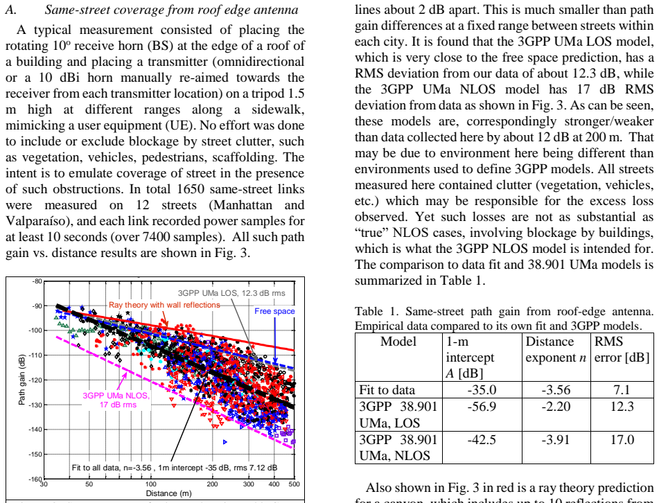
On the paper's own terms, the central discovery is a set of empirical propagation laws for 28 GHz urban street canyons measured from real rooftop heights. For roof-edge base antennas with a street directly in view, path gain follows Eq. (1): $PG = -35.0 + 10(-3.56)\log_{10}(d) + N(0, 7.1\ \text{dB})$ over 35 to 500 meters, equivalent to 11 dB excess loss at 200 meters and 20 dB at 500 meters relative to free space. Offsetting the antenna 5 meters from the roof edge causes 15 dB additional loss at 100 meters, a penalty that shrinks as range grows. Around a corner, a single-slope diffraction-inspired model with a 2.2 dB empirical corner loss fits the data with 3.4 dB RMS error. Finally, 90% of measured effective azimuth gains at the roof edge lie within 2 dB of the antenna's nominal gain, so scatter does not destroy the value of high-gain base antennas in street canyons.
Load-bearing premise
The absolute path-gain numbers rest on the assumption that averaging power over the rotating horn's full 360-degree sweep equals what an omnidirectional antenna would receive; if power arrives outside the scanned horizontal plane, every reported gain shifts.
Editorial extensions
If this is right
- Network planners can use the roof-edge path-gain law directly for same-street coverage: at 200 meters the budget must include 11 dB beyond free space plus a 7.1 dB shadow margin.
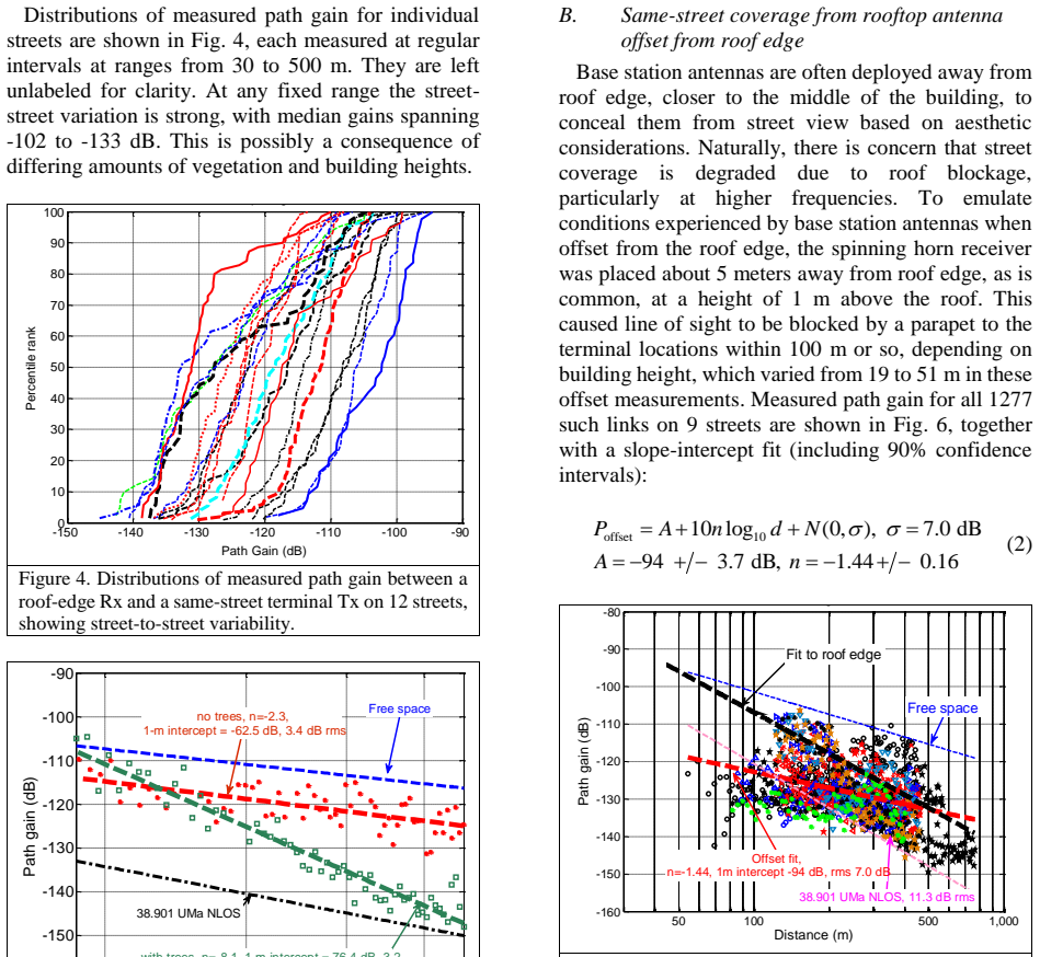
- Roof-edge placement is worth about 15 dB at 100 meters; offset deployments trade concealment for a distance-dependent range penalty that largely disappears at long range.
- Around-corner coverage follows a single-slope diffraction model with only about 2 dB corner loss, so street-canyon coverage extends around corners with predictable, modest drops.
- High-gain base antennas are effective: 90% of locations lose less than 2 dB of nominal azimuth gain, supporting 24 dBi-class arrays for 28 GHz.
- At 400-meter inter-site distance, about 12 sites per square kilometer, 90% of outdoor users can get theoretical rate limits above 350 Mbps with 800 MHz of bandwidth.
Reading between the lines
- A seasonal repeat of the tree-lined street, measured here without leaves, would separate canopy attenuation from trunk-and-branch scatter; the steep $-8.1$ distance exponent likely sets a lower bound on foliage loss.
- The small angular spread behind the 2 dB gain degradation suggests that even narrower-beam antennas than the tested 10-degree horn could retain most of their gain, but this campaign did not test them.
- The near-zero corner loss compared with theoretical deep-shadow diffraction implies that street furniture acts as secondary scatterers, which would push ray tracing toward diffuse-scattering terms rather than specular reflections alone.
- Because the setback penalty shrinks with distance, system-level link budgets should apply the offset fit as a distance-dependent model rather than a constant loss.
Signed reviews
Editorial analysis
A structured set of objections, weighed in public.
Referee Report
Summary. This paper reports an extensive 28 GHz measurement campaign in urban street canyons, using a rotating 10-degree horn receiver at rooftop macro sites and a low-height terminal on the street. Over 3000 links and 21 million CW power samples were collected across 12 streets in Manhattan and Valparaíso. The paper presents empirical slope-intercept path gain models for same-street roof-edge (Eq. (1), A=-35.0, n=-3.56, σ=7.1 dB), offset-from-roof-edge (Eq. (2)), and lamppost deployments, plus an around-corner diffraction-inspired model with an empirical corner loss of about 2 dB. It also quantifies effective azimuthal gain degradation, finding that 90% of roof-edge azimuth gains are within 2 dB of the nominal antenna gain, and uses the models in a system-level simulation to show that 90% of outdoor users can achieve 350 Mbps or higher at 400 m ISD.
Significance. The dataset is exceptionally large for mmWave street-canyon measurements, and the system calibration (0.15 dB absolute accuracy) is a strength. If the models are validated, they provide a useful empirical basis for 28 GHz coverage planning and for assessing the value of high-gain antennas in urban canyons. The finding that standard ray tracing overpredicts path gain by about 13 dB at 200 m is an important caution for simulation-based planning. The around-corner diffraction model with only two fitted parameters and 3.4 dB RMSE is a compact, useful result. However, the absolute path gain values rest on an azimuth-averaging equivalence that is not independently validated in this geometry, and one headline excess-loss number appears to be inconsistent with the fitted equation.
major comments (3)
- [II.C, Eq. (1)] The derivation of PG from P_all relies on the equivalence between the azimuthal average of the spinning-horn received power and the omnidirectional average power, citing equations (1)-(6) of [23], and on subtracting a nominal elevation gain Gelev. In the rooftop-to-street geometry, the elevation angle of the direct path to the 1.5 m-high terminal varies from about 2 degrees at 500 m to more than 20 degrees at 35 m (for roof heights of 15-51 m). Because the receive horn has a 10-degree elevation beamwidth, the assumption that the effective elevation gain equals the nominal Gelev at all ranges is not substantiated. A distance-dependent elevation bias would shift both the intercept A and the exponent n in Eq. (1), and thus the headline 11 dB excess loss at 200 m. The paper's justification, citing 3GPP 38.901 elevation-spread values, is a model assumption rather than a measurement in this environment. Please validate the equivalence (e.g., with a subset of links measured using an omnidirectional receive antenna) or quantify the elevation gain error; at minimum, state the horn's elevation pointing direction and the gain variation over the relevant elevation angles.
- [III.A] The claim that Eq. (1) implies an 11 dB excess loss at 200 m and 20 dB at 500 m relative to free space is inconsistent with the fitted parameters. Using A=-35.0, n=-3.56, and λ=10.7 mm, the excess loss is approximately 9.5 dB at 200 m and 15.7 dB at 500 m. Since these numbers appear in the abstract and conclusions, please recalculate and correct them, or clarify the reference used for the free-space baseline.
- [III.D, Eq. (3)] The second line of the diffraction model formula is dimensionally inconsistent as printed (the logarithm's argument has units of m^3). Because the fitted parameters in Table 2 and the conclusion that the diffraction model is best depend on this equation, please restate the equation cleanly and ensure it matches the model actually used for fitting.
minor comments (4)
- [I] The Introduction states that the models predict rates exceeding 300 Mbps for 90% of outdoor locations, while Section V reports 350 Mbps; please standardize the cited number.
- [II.A] The paper does not describe the elevation orientation (tilt) of the rotating receive horn; adding this detail would make the measurement setup reproducible and would help readers assess the elevation-gain assumption.
- [III.D] The text says the scattering model with Friis intercept has a corner loss of 0 dB; this means the model simply reduces to a single-slope model. It may help to state this explicitly when comparing models.
- [I] The claim that the data set allows 90% confidence intervals of under 1 dB for path gain and under 0.5 dB for effective directional gain is not directly tied to the reported ±2.7 dB intercept and ±0.12 slope intervals in Eq. (1); please clarify what quantity each confidence interval refers to.
Circularity Check
No significant circularity: the path-gain models are empirical fits to thousands of measured links, and the cited P_all-to-omnidirectional equivalence is a measurement-calibration input, not a predicted result.
full rationale
The paper's central claims are empirical fits, not derivations. Eq. (1) is explicitly a slope-intercept fit to 1650 measured same-street roof-edge links with 7.1 dB RMS error, and the 11 dB excess loss at 200 m is read off that fitted line. The offset and lamppost models are likewise fits, and the around-corner models in Eqs. (3)-(5) are candidate functional forms compared by RMS error, so model selection is data-driven. The only load-bearing self-citation is Section II.C, where the paper says 'The azimuthal average of received power over all angular directions, denoted as P_all, has been shown to be equivalent to the average omnidirectional power (see detailed derivation given by equation (1)--(6) in [23]).' This is a measurement-calibration equivalence used to convert raw power samples into path-gain values, not a prediction of Eq. (1); even if the equivalence were biased, it would be a calibration or modeling-risk issue rather than a circular derivation. The paper also benchmarks against external references (3GPP 38.901 models and ray theory), and the system-rate simulation transparently reuses the fitted propagation models, so it is extrapolation rather than a hidden prediction. No circular step is exhibited.
Assumptions & free parameters
free parameters (10)
- Roof-edge same-street path gain intercept A =
-35.0 dB
- Roof-edge same-street path gain exponent n =
-3.56
- Roof-edge same-street shadow fading sigma =
7.1 dB
- Offset same-street path gain intercept A =
-94 dB
- Offset same-street path gain exponent n =
-1.44
- Offset same-street shadow fading sigma =
7.0 dB
- Lamppost same-street path gain exponent n (fixed intercept) =
-2.37
- Around-corner diffraction model exponent n =
-2.27 (with Friis intercept); -2.63 (floating intercept)
- Around-corner empirical corner loss Delta =
2.2 dB (with Friis intercept); 0 dB (floating intercept)
- Rate simulation system parameters =
28 dBm Tx power, 23 dBi BS antenna, 6 dBi UE, 9 dB noise figure, 800 MHz bandwidth, 400 m ISD
assumptions (4)
- domain assumption Azimuthal average of received power over a full scan equals omnidirectional average power
- domain assumption Transmit antenna gain and receive elevation gain are undegraded by scattering
- domain assumption The two measured cities (Manhattan and Valparaíso) represent a useful class of dense urban street canyons
- domain assumption The rate simulation assumptions for network geometry (400 m ISD, 12 sites/sq km, cells at corners) are representative of future 5G deployments
Cite this review
Pith. "Pith review of Directional Measurements in Urban Street Canyons from Macro Rooftop Sites at 28 GHz for 90% Outdoor Coverage." pith.science (2026). https://pith.science/paper/YCYUIZVE
@misc{pith2026190800512,
  author       = {Pith},
  title        = {Pith review of: Directional Measurements in Urban Street Canyons from Macro Rooftop Sites at 28 GHz for 90% Outdoor Coverage},
  year         = {2026},
  howpublished = {\url{https://pith.science/paper/YCYUIZVE}},
  note         = {Machine review of arXiv:1908.00512}
}
read the original abstract
Path gain and effective directional gain in azimuth in urban canyons from actual rooftop base station sites are characterized based on a massive data set of 3000 links on 12 streets in two cities, with over 21 million individual continuous wave power measurements at 28 GHz using vertically polarized antennas. Large street-to-street path gain variation is found, with median street path gain varying over 30 dB at similar distances. Coverage in the street directly illuminated by a roof edge antenna is found to suffer an average excess loss of 11 dB relative to free space at 200 m, with empirical slope-intercept fit model representing the data with 7.1 dB standard deviation. Offsetting the base antenna 5 m away from roof edge, as is common in macro cellular deployments, introduces an additional average loss of 15 dB at 100 m, but this additional loss reduces with distance. Around the corner loss is well modeled by a diffraction formula with an empirically obtained diffraction coefficient. Effective azimuthal gain degradation due to scatter is limited to 2 dB for 90% of data, supporting effective use of high gain antennas in urban street canyons.
Figures
Figures from the paper (2 more)


Reference graph
Works this paper leans on
-
[23]
D. Chizhik, J. Du, R. Feick, G. Castro, M. Rodriguez and R. A. Valenzuela, “Path Loss and Directional Gain Measurements at 28 GHz for non -line-of-sight coverage of indoors with corridors ,” IEEE Transactions on Antennas and Propagation, vol. 68, pp. 4820- 4830, Jun. 2020
work page 2020
-
[1]
Experimental Propagation Channel Characterization of mm-Wave Radio Links in Urban Scenarios,
M. Kyro, V. Kolmonen and P. Vainikainen, "Experimental Propagation Channel Characterization of mm-Wave Radio Links in Urban Scenarios," IEEE Antennas and Wireless Propagation Letters, vol. 11, pp. 865-868, Aug. 2012
work page 2012
-
[2]
T. S. Rappaport, F. Gutierrez, E. Ben-Dor, J. N. Murdock, Y. Qiao and J. I. Tamir, "Broadband Millimeter -Wave Propagation Measurements and Models Using Adaptive -Beam Antennas for Outdoor Urban Cellular Communications," IEEE Transactions on Antennas and Propagation, vol. 61, pp. 1850-1859, Apr. 2013
work page 2013
-
[3]
H. J. Thomas, R. S. Cole and G. L. Siqueira, "An experimental study of the propagation of 55 GHz millimeter waves in an urban mobile radio environment," IEEE Transactions on Vehicular Technology, vol. 43, pp. 140-146, Feb. 1994
work page 1994
-
[4]
E-band propagation channel measurements in an urban street canyon,
V. Semkin, U. Virk, A. Karttunen, K. Haneda and A. V. Räisänen, "E-band propagation channel measurements in an urban street canyon," 2015 9th European Conference on Antennas and Propagation (EuCAP), Lisbon, Portugal, Apr. 2015
work page 2015
-
[5]
Microwave path-loss modeling in urban line -of-sight environments,
H. Masui, T. Kobayashi and M. Akaike, "Microwave path-loss modeling in urban line -of-sight environments," IEEE Journal on Selected Areas in Communications, vol. 20, pp. 1151 -1155, Aug. 2002
work page 2002
-
[6]
Simultaneous millimeter-wave multi-band channel sounding in an urban access scenario,
R. J. Weiler, M. Peter, T. Kühne, M. Wisotzki and W. Keusgen, "Simultaneous millimeter-wave multi-band channel sounding in an urban access scenario," 2015 9th European Conference on Antennas and Propagation (EuCAP), Lisbon, Portugal, Apr. 2015
work page 2015
-
[7]
Millimeter -wave channels in urban environments,
A. F. Molisch et al., "Millimeter -wave channels in urban environments," 2016 10th European Conference on Antennas and Propagation (EuCAP), Davos, Switzerland, Apr. 2016
work page 2016
Show all 31 references
-
[8]
Propagation measurements and simulations for millimeter -wave mobile access in a busy urban environment,
W. Keusgen, R. J. Weiler, M. Peter, M. Wisotzki and B. Göktepe, "Propagation measurements and simulations for millimeter -wave mobile access in a busy urban environment," 2014 39th International Conference on Inf rared, Millimeter, and Terahertz waves (IRMMW-THz), Tucson, AZ, ...
2014
-
[9]
Karttunen, A
A. Karttunen, A. F. Molisch, S. Hur, J. Park, C. J. Zhang, ”Spatially Consistent Street-by-Street Path Loss Model for 28 -GHz Channels in Micro Cell Urban Environments”, IEEE Transactions on Wireless Communications, vol.16, pp. 7538-7550, Nov. 2017
2017
-
[10]
Frequency -agile pathloss models for urban street canyons,
K. Haneda, N. Omaki, T. Imai, L. Raschkowski, M. Peter and A. Roivainen, “Frequency -agile pathloss models for urban street canyons,” IEEE Transactions on Antennas and Propagation, vol. 64, pp. 1941-1951, May 2016
1941
-
[11]
5G 3GPP-like channel models for outdoor urban microcellular and macrocellular environments,
K. Haneda et al., “5G 3GPP-like channel models for outdoor urban microcellular and macrocellular environments,” IEEE Vehicular Technology Conference (VTC Spring), Nanjing, China, May 2016
2016
-
[12]
Overview of millimeter wave communications for fifth-generation (5G) wireless networks-with a focus on propagation models,
T. S. Rappaport, Y. Xing, G. R. MacCa rtney, A. F. Molisch, E. Mellios and J. Zhang, “Overview of millimeter wave communications for fifth-generation (5G) wireless networks-with a focus on propagation models,” IEEE Transactions on Antennas and Propagation, vol. 65, pp. 6213-62...
2017
-
[13]
Millimeter -Wave Channel Measurements and Analysis for Statistical Spatial Channel Model in In -Building and Urban Environments at 28 GHz
J. Ko, Y.-J. Cho, S. Hur, T. Kim, J. Park, A. F. Molisch, K. Haneda, M. Peter, D. Park, D. -H. Cho, “Millimeter -Wave Channel Measurements and Analysis for Statistical Spatial Channel Model in In -Building and Urban Environments at 28 GHz”, IEEE Transactions on Wireless Commun...
2017
-
[14]
Millimeter wave channel measurement and implications for PHY layer design
V. Raghavan, A. Partyka, L. Akhoondzadeh -Asl, M. A. Tassoudji, O. H. Koymen and J. Sanelli “Millimeter wave channel measurement and implications for PHY layer design”, IEEE Transactions on Antennas and Propagation, vol. 65, pp. 6521-6533, Dec. 2017
2017
-
[15]
28 GHz millimeter wave cellular communication measurements for reflection and penetration loss in and around buildings in New York city,
H. Zhao, R. Mayzus, S. Sun, M. Samimi, J. K. Schulz; Y. Azar, K. Wang, G. N. Wong, F. Gutierrez, T. S. Rappaport, “28 GHz millimeter wave cellular communication measurements for reflection and penetration loss in and around buildings in New York city,” IEEE International Confer...
2013
-
[16]
Stationarity region of Mm-Wave channel based on outdoor microcellular measurements at 28 GHz,
R. Wang, C. U. Bas, S. Sangodoyin, S. Hur, J. Park, J. Zhang and A. F. Molisch, “Stationarity region of Mm-Wave channel based on outdoor microcellular measurements at 28 GHz,” IEEE Military Communications Conference (MILCOM), Baltimore, MD, Oct. 2017
2017
-
[17]
Frequency range extension of the ITU-R NLOS path loss models applicable for urban street environments with 28 GHz measurements,
J. Lee, M. Kim, J. Liang, J. Park and B. Park, "Frequency range extension of the ITU-R NLOS path loss models applicable for urban street environments with 28 GHz measurements," 2016 10th European Conference on Antennas and Propagation (EuCAP), Davos, Switzerland, Apr. 2016
2016
-
[18]
Angular Resolved Pathloss Measurements in Urban Macrocell Sce narios at 28 GHz,
C. Larsson, B. Olsson and J. Medbo, "Angular Resolved Pathloss Measurements in Urban Macrocell Sce narios at 28 GHz," 2016 IEEE 84th Vehicular Technology Conference (VTC -Fall), Montreal, Canada, Sept. 2016
2016
-
[19]
Proposal on Millimeter-Wave Channel Modeling for 5G Cellular System,
S. Hur et al., "Proposal on Millimeter-Wave Channel Modeling for 5G Cellular System," IEEE Journal of Selected Topics in Signal Processing, vol. 10, pp. 454-469, Apr. 2016
2016
-
[20]
Study on channel model for frequencies from 0.5 to 100 GHz,
“Study on channel model for frequencies from 0.5 to 100 GHz,” 3GPP Technical Report TR 38.901 v14.1.1, Jul. 2017. http://www.3gpp.org/ftp/specs/archive/38_series/38.901/38901- e11.zip
2017
-
[21]
Further advancements for E-UTRA physical layer aspects (Release 9)
“Further advancements for E-UTRA physical layer aspects (Release 9)”, 3GPP Technical Report TR 36.814, V9.2.0, Mar. 2017
2017
-
[22]
Guidelines for evaluation of radio interface technologies for IMT- Advanced,
“Guidelines for evaluation of radio interface technologies for IMT- Advanced,” ITU-R Report M.2135-1, Dec. 2009
2009
-
[24]
Suburban Fixed Wireless Access Channel Measurements and Models at 28 GHz for 90% Outdoor Coverage,
J. Du, D. Chizhik, R. Feick, M. Rodríguez, G. Castro and R. A. Valenzuela, "Suburban Fixed Wireless Access Channel Measurements and Models at 28 GHz for 90% Outdoor Coverage," IEEE Transactions on Antennas and Propagation, vol. 68, pp. 411 - 420, Jan. 2020
2020
-
[25]
“Propagation data and prediction methods for the planning of short- range outdoor radio communication systems and radio local area networks in the frequency range 300 MHz to 100 GHz,” Recommendation ITU-R P.1441-9, Jun. 2017
2017
-
[26]
Path loss chara cteristics at 800 MHz to 37 GHz in urban street microcell environment,
M. Sasaki, W. Yamada, T. Sugiyama, M. Mizoguchi and T. Imai, "Path loss chara cteristics at 800 MHz to 37 GHz in urban street microcell environment," 2015 9th European Conference on Antennas and Propagation (EuCAP), Lisbon, Portugal, Apr. 2015
2015
-
[27]
Asymptotic minimax character of the sampl e distribution function and of the classical multinomial estimator,
A. Dvoretzky; J. Kiefer, J. Wolfowitz, (1956). "Asymptotic minimax character of the sampl e distribution function and of the classical multinomial estimator," Annals of Mathematical Statistics, vol. 27, pp. 642-669, Sept. 1956
1956
-
[28]
H. L. Bertoni, Radio Propagation for Modern Wireless Systems, Prentice Hall, 2000
2000
-
[29]
Site-Specific Models of the Received Power for Radio Communication in Urban Street Canyons,
J. S. Lu, H. L. Bertoni, K. A. Remley, W. F. Young and J. Ladbury, "Site-Specific Models of the Received Power for Radio Communication in Urban Street Canyons," IEEE Transactions on Antennas and Propagation, vol. 62, pp. 2192-2200, Apr. 2014
2014
-
[30]
Multi -band Double -directional 5G Street Canyon Measurements in Germany,
D. Dupleich, R. Müller, S. Skoblikov, J. Luo, G. Del Galdo and R. S. Thomä, "Multi -band Double -directional 5G Street Canyon Measurements in Germany," 2019 European Conference on Networks and Communications (EuCNC), Valencia, Spain, Jun. 2019
2019
-
[31]
Multi -band Propagation and Radio Channel Characterization in Street Canyon Scenarios for 5G and Beyond,
D. Dupleich et al., "Multi -band Propagation and Radio Channel Characterization in Street Canyon Scenarios for 5G and Beyond," IEEE Access, vol. 7, pp. 160385-160396, Oct. 2019
2019
Reviewed August 14, 2026 · model on record in the stance chip above.
Discussion (0). Continue with ORCID to comment.