REVIEW 3 major objections 5 minor 9 references
Pointing System for the Large Size Telescopes Prototype of the Cherenkov Telescope Array
T0 review · 3 major / 5 minor · reviewed 2026-08-14 · deepseek-v4-flash
Pith's one-line read This paper reports a multi-sensor pointing system designed to give the LST-1 Cherenkov telescope a post-calibration pointing precision better than 14 arcseconds, with laboratory tests showing each key device meets its target.
desk verdict A solid engineering design note for the LST-1 pointing system, useful as a status report, but the abstract's 14-arcsecond claim is not backed by quantitative results in the paper. read the letter →
The pith
A machine-rendered reading of the paper's core claim, the machinery that carries it, and where it could break.
The reading
What carries the argument
The load-bearing mechanism is a two-camera reference chain plus a laser-defined axis. The Starguider anchors the camera to the sky; the Camera Displacement Monitor anchors the optical axis to the camera through the OARL laser spots and the ring of reference LEDs; inclinometers and distance meters tie the dish to the drive system. The OARL is a laser that defines the telescope's optical axis during observations, and a stiff unit in which two such lasers sandwich an inclinometer lets the dish-center inclination stand for the whole dish. The final link is the inter-calibration that registers the Starguider and Camera Displacement Monitor frames, computed from six shared LEDs seen by both cameras, without which the two camera measurements cannot be combined.
What would settle it
Point the fully assembled telescope at a bright star, take simultaneous Starguider and Camera Displacement Monitor data while wind gusts are present, reconstruct the source position from the Cherenkov images, and compare with the star's known astrometric position; if the RMS space-angle deviation exceeds 14 arcseconds, the central claim fails.
Extended reading notes
Core claim
The central claim is that the assembled pointing system, rather than any single device, is what delivers the precision. The Starguider determines the camera center in sky coordinates with a precision of 5 arcseconds by matching recorded star fields to a catalogue and by locating reference LEDs around the photomultiplier-tube camera. The Camera Displacement Monitor, operating at 10 Hz, observes two laser spots that define the telescope's optical axis together with the same LEDs, so it can measure the deviation of the optical axis from the camera center to better than 5 arcseconds. Inclinometers and distance meters measure dish tilt and camera-plane distance and tilt, feeding a bending model used for online corrections, while the two camera systems are combined offline after an inter-calibration based on six LEDs seen by both. The paper's result is that each component meets its precision target on the test bench, and the design is expected to deliver the required <14 arcsecond post-calibration pointing precision on the telescope.
Load-bearing premise
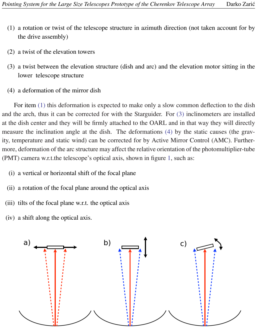
The load-bearing premise is that the precision measured for each component alone on a test bench carries over to the fully assembled 28-meter telescope under gravity, temperature changes, and wind, and that the two cameras can be inter-calibrated on the sky with the same accuracy as in the laboratory.
Editorial extensions
If this is right
- If the system performs on the telescope as it did on the test benches, LST-1 will localize gamma-ray sources to better than 14 arcseconds RMS after calibration, meeting the observatory's science requirement.
- The online bending model can keep the telescope pointed during slow gravitational sag, while the 10 Hz Camera Displacement Monitor can catch wind-gust oscillations around 2 Hz that a once-per-second Starguider would miss.
- Separating deformations into categories lets each contributor be corrected by the device best suited to measure it: inclinometers for dish tilt, distance meters for camera-plane movement, the Starguider for slow overall offsets, and the Camera Displacement Monitor for fast camera-dish relative motion.
- The offline correction method of combining a star-tracker position with a camera-displacement measurement directly addresses the known limitation that elastic bending models cannot correct for temperature or wind deformations.
Reading between the lines
- A natural extension the paper leaves implicit: if the 5 arcsecond Starguider error and the better-than-5 arcsecond Camera Displacement Monitor error are independent, the combined offline correction should land near $\sqrt{5^2+5^2}\approx7$ arcseconds, leaving comfortable margin under the 14 arcsecond requirement.
- The decisive unproven step is the on-sky inter-calibration of the two cameras through six shared LEDs at the 3-degree tilt expected on the telescope; a future end-to-end test against a bright star would settle whether the lab-measured component precision actually compounds as designed.
- The same architecture of a sky-pointing camera, a structure-pointing camera, shared LED fiducials, and a laser-defined axis could be transferred to other ground-based gamma-ray or optical telescopes whose structures deform faster than a star tracker can sample.
Signed reviews
Editorial analysis
A structured set of objections, weighed in public.
Referee Report
Summary. This proceedings paper describes the design of the pointing system for the prototype Large Size Telescope (LST-1) of CTA. The system combines a Starguider camera (SG), a Camera Displacement Monitor (CDM), two inclinometers, four distance meters, an Optical Axis Reference Laser (OARL), and reference LEDs to correct telescope deformations and achieve a post-calibration pointing precision better than 14 arcseconds. The authors classify deformation sources, assign monitoring devices to each class, and outline online correction via a bending model and offline correction via SG and CDM measurements. They report that laboratory measurements on test benches showed the required precision can be achieved for SG, CDM, and inclinometers, while the SG–CDM inter-calibration procedure is described as planned and expected to be installed by the end of August 2019.
Significance. The paper's value is conceptual: it gives a clear decomposition of the deformation sources affecting an IACT pointing system and maps each source to a specific monitoring device. This architecture—notably the rigid OARL-inclinometer unit, the high-rate CDM to handle wind-gust oscillations, and the offline use of a star camera together with a camera displacement monitor—is a sensible engineering design and is presented in a reasonably coherent way. The use of established tools (WCSTools, SExtractor, SciPy kd-tree) and the explicit separation of static and dynamic deformations are strengths. However, the headline claim that the required pointing precision can be achieved is currently supported only by unquantified references to laboratory measurements and by planned procedures; no integrated end-to-end validation is presented. If the authors supply the missing quantitative test data and clearly delimit the claim to component-level readiness, the paper would be a useful status report for the IACT community.
major comments (3)
- [Abstract; §3.4 and §3.5] The abstract states: 'Laboratory measurements on dedicated test benches showed that the required pointing precision can be achieved for SG, CDM and inclinometer.' Yet no quantitative results, uncertainties, or test conditions are reported for any of these devices. The precision numbers that do appear (§3.4: 14 arcsec and 1 arcsec for the two inclinometers; §3.5: 7 arcsec/pixel sampling for CDM) are specifications or design parameters, not measured performance. As written, the abstract's feasibility claim outruns the evidence presented in the paper. This is load-bearing because the 14 arcsecond requirement applies to the integrated post-calibration pointing precision, not to individual components. The authors should either report the laboratory measurements in quantitative detail or explicitly rephrase the claim as component-level test-bench readiness.
- [§4] Section 4 identifies a drawback of the two-camera solution: a careful inter-calibration between the SG and CDM frames is needed, using six shared LEDs with a 3-degree tilt, followed by 'several thousand images' once the system is mounted on the telescope. The text says the software tool 'will be tested in the laboratory first' and that installation is 'expected... by the end of August 2019.' This is explicitly a planned procedure, not a demonstrated one. The transformation between the SG camera frame and the CDM frame is central to converting camera-pixel coordinates to sky coordinates, so the absence of any inter-calibration result means the central precision claim is not yet supported for the integrated system. The authors should either present the planned calibration method with an error budget or clearly state that the 14 arcsecond claim awaits on-telescope validation.
- [§3.5.1; §2] The bending model is described as the basis for online pointing corrections, with parameters including axis offsets, non-perpendicularities, non-centricity, and a zenith-dependent optical-axis deflection. However, the paper does not provide the model equations, the method by which the parameters are constrained, or any validation (e.g., against the finite-element analysis cited in §2 or against test-bench data). Section 3.5.1 says the 'same camera will be used for generating the bending models' and describes the observation procedure, but no result or expected accuracy is given. Since the online correction depends on this model, the paper's claim about achieving the required pointing precision cannot be assessed without at least a statement of the model's expected residual error or a reference to a validation study.
minor comments (5)
- [Abstract; §1] Minor language issues: 'precision system consist of' should be 'consists of', and the abstract's long first sentence could be split for clarity. These do not affect the technical content.
- [§3.2.1] The utility name is spelled 'immach' in two places; the correct name of the WCSTools routine is 'immatch'. Please correct the typo.
- [§3.6] The distance meters are said to have '±15mm of accuracy'. This is ambiguous: is this the per-measurement accuracy, the systematic offset, or the resolution? Please specify the uncertainty convention and, ideally, whether it refers to the 28 m measurement range.
- [§3.4] The inclinometer precisions are quoted as 14 arcsec and 1 arcsec, but it is not stated whether these are RMS, peak-to-peak, or systematic errors. Clarifying this would help the reader compare them with the 14 arcsecond overall requirement.
- [§4] The paper refers to reference [9] for the transformation-matrix calculation but does not give the expected numerical precision of that method or its sensitivity to the 3-degree tilt. A sentence quantifying the expected contribution of the inter-calibration to the error budget would strengthen the outlook.
Circularity Check
No circularity: the paper reports an engineering design and component test-bench results; the 14 arcsecond claim is an extrapolation to the integrated telescope, not a derivation from fitted inputs.
full rationale
The paper contains no fitted parameter that is renamed as a prediction, no equation whose output is identical to its input by construction, and no load-bearing argument that reduces to a self-citation. The central claim, 'Laboratory measurements on dedicated test benches showed that the required pointing precision can be achieved for SG, CDM and inclinometer', is a statement about individual component test benches; it does not derive the end-to-end post-calibration pointing precision. The bending model parameters listed in Section 3.5.1 are not fitted or evaluated here, so there is no statistical circularity. The SG-CDM inter-calibration, which the paper itself calls a 'drawback' requiring 'careful inter-calibration between the cameras', is explicitly described in Section 4 as a planned procedure to be tested in the laboratory and later on the telescope, with installation expected at the end of August 2019. The paper is therefore self-consistent: the only weakness is an extrapolation from component-level laboratory tests to integrated system performance, which is an evidentiary gap, not a circularity. Self-citations such as references [5] and [6] are supporting design inputs, not uniqueness theorems or unverified premises that force the paper's conclusions. Accordingly, the correct circularity score is 0.
Assumptions & free parameters
assumptions (3)
- domain assumption Finite element analysis of the LST structure correctly models the deformation of the dish and arch.
- domain assumption The six reference LEDs shared between SG and CDM provide sufficient constraints for the inter-camera transformation matrix at the expected 3 degree mounting tilt.
- domain assumption Laboratory test bench measurements are representative of on-telescope performance.
Cite this review
Pith. "Pith review of Pointing System for the Large Size Telescopes Prototype of the Cherenkov Telescope Array." pith.science (2026). https://pith.science/paper/Q4KS3UWS
@misc{pith2026190801269,
  author       = {Pith},
  title        = {Pith review of: Pointing System for the Large Size Telescopes Prototype of the Cherenkov Telescope Array},
  year         = {2026},
  howpublished = {\url{https://pith.science/paper/Q4KS3UWS}},
  note         = {Machine review of arXiv:1908.01269}
}
read the original abstract
The pointing system of the prototype of the Large Size Telescope (LST-1) for the Cherenkov Telescope Array observatory, should ensure mapping of the gamma-ray image of a point-like source in the Cherenkov camera to the sky coordinates with a precision better than 14 arcseconds. Detailed studies of the telescope deformations are performed in order to disentangle different deformations and quantify their contributions to the miss-pointing, to learn how to correct for them, and finally how to design the system for offline and online pointing corrections. The LST-1 pointing precision system consist of several devices mounted at the center of the dish: Starguider Camera (SG), Camera Displacement Monitor (CDM), two inclinometers, four distance meters, and an Optical Axis Reference Laser (OARL), working together with the LEDs mounted in a circle around the Cherenkov camera. The online pointing corrections are based on a bending model as currently done by existing IACTs. The offline corrections will be performed combining measurements done by the SG and CDM cameras. SG will provide the position of the Cherenkov camera center with respect to the sky coordinates with a precision of 5 arcseconds, while CDM will provide the deviation of the telescope optical axis defined by the OARL spots with respect to the Cherenkov camera center with a precision better than 5 arcseconds. Laboratory measurements on dedicated test benches showed that the required pointing precision can be achieved for SG, CDM and inclinometer.
Figures


Reference graph
Works this paper leans on
-
[1]
J. Cortina for the CTA consortium, Status of the Large Size Telescope of the Cherenkov Telescope Array, in proceedings of 36th International Cosmic Ray Conference, PoS(ICRC2019) (2019)
work page 2019
-
[2]
www.cta-observatory.org/project/technology
- [3]
-
[4]
Wallace, TPOINT–Telescope Pointing Analysis System, Starlink User Note 100, 1994
P.T. Wallace, TPOINT–Telescope Pointing Analysis System, Starlink User Note 100, 1994
work page 1994
-
[5]
Noda, Alignment and pointing corrections and procedures, CTA LST/140721 (internal publication)
K. Noda, Alignment and pointing corrections and procedures, CTA LST/140721 (internal publication)
-
[6]
K. Noda, LST pointing and alignment performance with the finite element analysis , CTA LST/20140729 (internal publication)
-
[7]
D. J. Mink, WCSTools: Image World Coordinate System Utilities, In Astronomical Data Analysis Software and Systems VI (V ol. 125, p. 249). (1997)
work page 1997
-
[8]
D. J. Mink, Browsing Images in World Coordinate Space with SAOimage, In Astronomical Data Analysis Software and Systems V (V ol. 101, p. 96). (1996)
work page 1996
Show all 9 references
-
[9]
Cashbaugh, C
J. Cashbaugh, C. Kitts: Automatic Calculation of a Transformation Matrix Between Two Frames, IEEE Access 6 9614-9622. (2018) [10.1109/ACCESS.2018.2799173] 7
2018
Reviewed August 14, 2026 · model on record in the stance chip above.
Discussion (0). Continue with ORCID to comment.