REVIEW 4 major objections 6 minor 18 references
Deformation of flexible ferromagnetic filaments under a rotating magnetic field
T0 review · 4 major / 6 minor · reviewed 2026-08-14 · deepseek-v4-flash
Pith's one-line read Low-frequency deformation of DNA-linked ferromagnetic filaments in a rotating field follows a linear law, θ ∝ f/H, whose slope yields the particle magnetic moment and whose relaxation yields the bending modulus.
desk verdict Solid experimental characterization with a clean scaling law and an interesting out-of-plane observation, but the reported material parameters are more loosely pinned than the text suggests. read the letter →
The pith
A machine-rendered reading of the paper's core claim, the machinery that carries it, and where it could break.
The reading
What carries the argument
The central comparison is between magnetic torque and viscous drag, expressed through the magnetoelastic number Cm = M H L²/A_b and the elastic relaxation time τ = ζ L⁴/A_b with drag coefficient ζ = 4πη. The load-bearing relation is Eq. (1), θ = 0.086 ωτ/Cm, taken from numerical simulations of ferromagnetic filament dynamics; inserting the measured dθ/df versus 1/H slope solves for the magnetic moment. For the relaxation measurement, the load-bearing element is the fundamental relaxation rate 3.934 L⁻⁴ A_b/ζ of a free elastic rod, which converts the measured relaxation decrements into A_b.
What would settle it
Measure dθ/df versus 1/H for the same filament while independently determining its magnetic moment (for example, with vibrating-sample magnetometry of the beads) and check whether the inferred m = 9.01×10⁻¹¹ emu is reproduced; also repeat the relaxation measurement at different distances between the filament and the glass wall to see whether the decrement, and thus A_b, changes with wall proximity.
Extended reading notes
Core claim
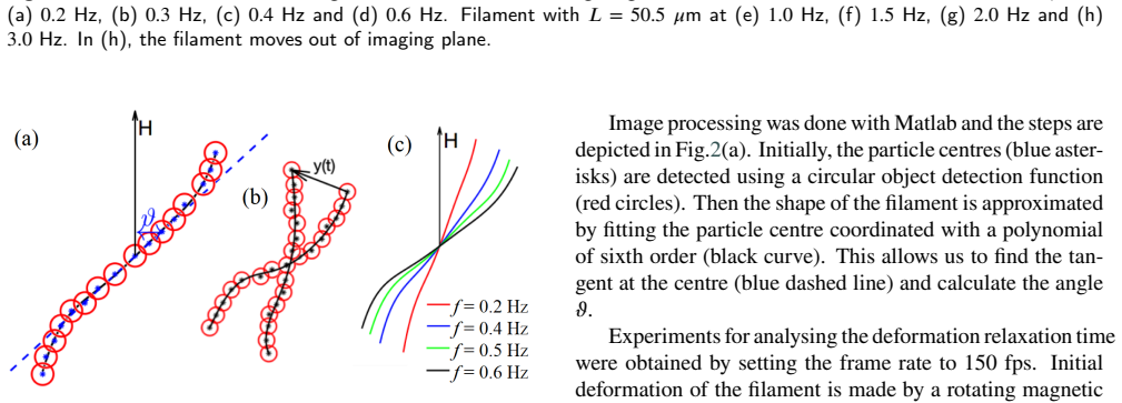
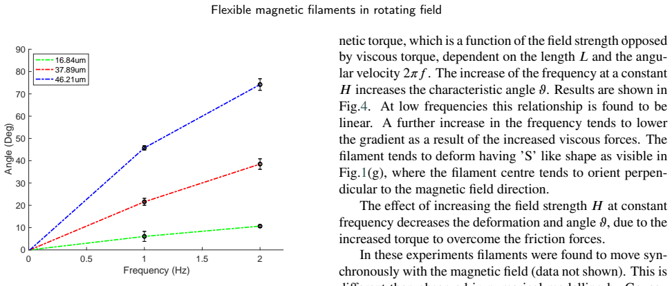
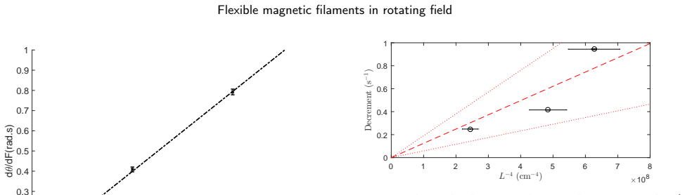
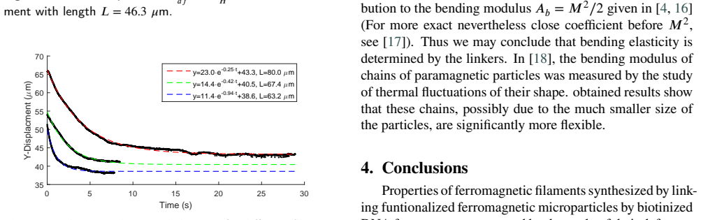
On the paper's own terms, a ferromagnetic filament sedimented on a glass surface and driven by a field rotating in-plane develops a characteristic S-shaped deformation that can be quantified by the tangent angle θ at the filament center. In the low-frequency regime θ is proportional to the rotation frequency f and inversely proportional to field strength H, i.e. dθ/df = a/H, with a = 6.8 Oe·s for a filament of length L = 46.3 μm. Combining that measured slope with the numerical relation θ = 0.086 ωτ/Cm (Eq. 1) yields a magnetization per unit length M = 2.14×10⁻⁷ emu and a per-particle magnetic moment m = 9.01×10⁻¹¹ emu. Separately, the exponential relaxation of the filament tip after the field is switched off, with decrements scaling as L⁻⁴, gives an average bending modulus A_b = (6.5 ± 3.4)×10⁻¹³ erg·cm, which is almost two orders of magnitude larger than the dipolar contribution M²/2, indicating that the DNA linkers determine the bending stiffness.
Load-bearing premise
The quantitative particle moment rests on the numerical constant 0.086 in Eq. (1), assumed transferable from earlier simulations to these DNA-linked ferromagnetic filaments, and on the drag coefficient being the free-space value ζ = 4πη with no wall correction.
Editorial extensions
If this is right
- Longer filaments deform more at fixed frequency and field because the magnetic torque scales with L² while the viscous resistance grows with L⁴, so bending is easier for longer chains.
- The measured slope a = 6.8 Oe·s provides a route to estimate particle magnetic moment from video microscopy alone, without separate magnetization equipment.
- The bending modulus obtained by relaxation is about two orders of magnitude above the dipolar estimate M²/2, so the DNA linkers, not magnetic interactions, set the elasticity.
- As frequency increases, filaments leave the plane of rotation once the center angle nears 90 degrees, before any asynchronous back-and-forth regime is reached, in contrast to the asynchronous dynamics predicted numerically for similar filaments.
- The implied persistence length is on the order of several tenths of centimeters, so these synthesized ferromagnetic filaments are quite stiff.
Reading between the lines
- The same protocol could be applied to filaments of other compositions, but the coefficient 0.086 in Eq. (1) should first be re-derived for each new geometry because it may depend on the numerical model's resolution and on details of the magnetic particle arrangement.
- Because the filaments sediment and slide on a glass wall, setting ζ = 4πη neglects wall drag; correcting for wall proximity would shift both reported quantities, likely lowering the inferred magnetic moment and increasing the bending modulus.
- The out-of-plane transition near θ = 90 degrees suggests a bifurcation that could be tested by tracking the filament's axial coordinate; if confirmed, it offers a way to measure the same elastic constants from full three-dimensional dynamics.
- The relaxation decrement's dependence on L⁻⁴ could be checked with filaments of controlled length distribution to separate linker elasticity from wall-friction effects.
Signed reviews
Editorial analysis
A structured set of objections, weighed in public.
Referee Report
Summary. The paper reports an experimental study of DNA-linked ferromagnetic microparticle filaments in a rotating magnetic field. Using video microscopy with a synchronized trigger, the authors measure the tangent angle at the filament center as a function of field frequency and strength. They observe that the angle increases linearly with frequency in the low-frequency regime, that longer filaments deform more, and that stronger fields reduce the deformation; at sufficiently high frequency the filament leaves the imaging plane. The linear slopes are fitted as dθ/df = a/H with a = 6.8 Oe·s and combined with the numerical relation θ = 0.086 ωτ/Cm from Ref. [7] to estimate a magnetization per unit length M = 2.14×10⁻⁷ emu and a particle magnetic moment m = 9.01×10⁻¹¹ emu. Relaxation experiments on three filaments give exponential decrements, and a fit against L⁻⁴ yields a bending modulus A_b = (6.5±3.4)×10⁻¹³ erg·cm. The authors conclude that the filaments are stiff, with a persistence length on the order of tens of centimeters.
Significance. The qualitative phenomenology reported here—larger deformation at higher frequency and longer length, smaller deformation at higher field, and a linear low-frequency regime—is internally consistent and useful for applications such as microfluidic mixing and biosensing. The experimental protocol, including synchronized imaging and direct measurement of the center tangent angle, is straightforward, and the relaxation data provide an independent cross-check on elasticity. If the quantitative extraction is accepted, the paper offers a simple route to estimate magnetic moment and bending modulus of ferromagnetic microfilaments. However, the central quantitative claims depend on an imported numerical coefficient and on an unbounded-fluid drag model that are not validated for the wall-adjacent filaments used here, and the main slope fit has no reported uncertainty. These issues place the quantitative conclusions on less secure footing than the qualitative trends.
major comments (4)
- [Section 3, Eq. (1)] The quantitative extraction of the magnetic moment is not self-contained: Eq. (1) imports the numerical coefficient 0.086 from the authors' earlier paper [7], but the present manuscript gives no derivation, no stated range of validity in H, L, or frequency, and no error estimate for that coefficient. Because Eq. (1) makes m linearly proportional to 0.086, any error in this calibration factor enters the reported m=9.01×10⁻¹¹ emu directly, and the comparison with [7] is not an independent validation since it uses the same coefficient from the same group. The authors should either derive the prefactor for the present geometry or provide a sensitivity analysis of m to this coefficient.
- [Section 3, hydrodynamic drag coefficient] The manuscript states that the filaments sediment to the bottom of the fluidic cell, yet it uses ζ=4πη for the hydrodynamic drag coefficient, which is the unbounded-fluid value for a rod. For a filament resting on a glass surface, the wall increases the drag (often by a factor of order 2 or more for close contact), and both headline material parameters inherit this error: the slope fit gives M ∝ ζ and the relaxation decrement fit gives A_b ∝ ζ. No wall correction or bound on its magnitude is provided, so the reported magnetic moment and bending modulus have an unquantified systematic uncertainty. This is a load-bearing assumption and should be addressed, for example by including a wall-correction estimate or by repeating the analysis with bracketing drag values.
- [Section 3, Figs. 4 and 5] The slope a=6.8 Oe·s is obtained from measurements on a single filament at three field strengths, and the paper does not show error bars on the θ(f) data or on the dθ/df versus 1/H plot, report repeated measurements, or give a goodness-of-fit statistic for the forced-origin linear fit. As a result, the extracted magnetic moment has no stated statistical uncertainty. At minimum, the authors should report the number of independent trials, per-point standard deviations, and the fit uncertainty on a before propagating it to M and m.
- [Section 3, Fig. 3 and Eq. (1)] Eq. (1) implies that the low-frequency slope dθ/df at fixed H should scale as L², but the three filament lengths shown in Fig. 3 are not used to test this prediction. Adding this check would provide a direct, internally consistent validation of Eq. (1) for the present system, rather than relying solely on the coefficient imported from [7]. If the L² scaling is not satisfied, the quantitative interpretation in terms of m and A_b would need to be revised.
minor comments (6)
- [Conclusions] The statement that the persistence length has the order of magnitude of 'several tenths of centimeters' appears inconsistent with the reported A_b=6.5×10⁻¹³ erg·cm, which gives A_b/(k_B T) ≈ 16 cm at room temperature; please correct this to 'tens of centimeters' or show the calculation.
- [Section 2.1] The text says '4.26 μm large' where '4.26 μm diameter' would be more precise, and the viscosity of the TE buffer used in ζ=4πη is not specified.
- [Section 3, paragraph after Fig. 4] The text says the field strength is between 6 Oe and 25 Oe, whereas Fig. 4 uses 25.8 Oe; please reconcile the numbers.
- [Fig. 5] The y-axis label 'd /dF(rad.s)' should be typeset as dθ/df (rad s⁻¹) and the x-axis label as 1/H (Oe⁻¹) for clarity.
- [Fig. 7 caption] The statement that the red dotted lines are 'confidence intervals for 3σ' is ambiguous; specify whether these are a 99.7% confidence band on the fit, a prediction band, or something else, and state how many measurements contribute to the fit.
- [Section 3, relaxation paragraph] The text notes that the filament does not return to its original shape and attributes this to damaged bonds or wall surface drag; please clarify whether the offset term in the exponential fits is included in the reported decrements and whether the physical origin of the offset was accounted for.
Circularity Check
No significant circularity: the fitted slope and the imported numerical coefficient 0.086 are distinct inputs, and the relaxation modulus uses an independent external eigenvalue.
full rationale
The derivation chain is self-contained in the required sense. The experimental slope a=6.8 Oe·s in Fig. 5 is an independent fit to the measured dθ/df versus 1/H data. The magnetic moment follows by algebra from the fixed numerical relation θ=0.086ωτ/Cm (Eq. 1) imported from [7], and that coefficient is not re-fitted to the present data. Substituting τ=ζL⁴/A_b and Cm=MHL²/A_b cancels A_b and leaves M=0.086·2π·ζL²/a, so the fitted slope and the coefficient are distinct inputs; the output m is not the fit renamed. The bending modulus A_b is obtained independently from measured relaxation decrements converted with the external eigenvalue 3.934 from Wiggins et al. [15]; fitting decrements versus L⁻⁴ is a standard model inversion, not a tautology. Although Eq. (1) comes from the same laboratory, it is a fixed, parameter-free numerical benchmark whose stated assumptions do not include the present fitted values, so under the review rules it counts as independent support rather than load-bearing self-citation. Concerns about ζ=4πη neglecting wall effects and the small number of relaxation lengths are correctness or uncertainty risks, not circularity.
Assumptions & free parameters
free parameters (2)
- slope a in dtheta/df = a/H =
6.8 Oe s
- relaxation decrements =
0.25, 0.42, 0.94 s^-1
assumptions (4)
- domain assumption The numerical relation theta = 0.086 omega tau / Cm from [7] describes the low-frequency deformation of ferromagnetic filaments in a rotating field.
- domain assumption Hydrodynamic drag per unit length is zeta = 4 pi eta, an unbounded-fluid slender-body estimate.
- standard math The relaxation of a free, unclamped elastic rod is governed by the smallest bending mode with decrement 3.934 L^-4 Ab / zeta.
- domain assumption The viscosity of the TE buffer is approximately that of water at room temperature.
Cite this review
Pith. "Pith review of Deformation of flexible ferromagnetic filaments under a rotating magnetic field." pith.science (2026). https://pith.science/paper/3RQUVSQR
@misc{pith2026190802604,
  author       = {Pith},
  title        = {Pith review of: Deformation of flexible ferromagnetic filaments under a rotating magnetic field},
  year         = {2026},
  howpublished = {\url{https://pith.science/paper/3RQUVSQR}},
  note         = {Machine review of arXiv:1908.02604}
}
read the original abstract
Research on magnetic particles dispersed in a fluid medium, actuated by a rotating magnetic field, is becoming increasingly active for both lab-on-chip and bio-sensing applications. In this study, we experimentally investigate the behaviour of ferromagnetic filaments in a rotating field. Filaments are synthesized by linking micron-sized ferromagnetic particles with DNA strands. The experiments were conducted under different magnetic field strengths, frequencies and filament sizes, and deformation of the filaments was registered via microscope and camera. The results obtained showed that the body deformation is larger for longer filaments and higher frequencies and lower for larger magnetic field. The angle between the filament tangent at the centre and the magnetic field direction increases linearly with frequency at low-frequency regime. A further increase in the frequency will result in filament movement out of plane when the angle approaches 90 degrees. The experimental results were used to estimate magnetic moment and the bending elasticity of the filament.
Figures

Figures from the paper (3 more)

Reference graph
Works this paper leans on
-
[7]
K. ¯Erglis, R. Livanovi/uni010Ds, A. C¯ebers, Three dimensional instability of flexible ferromagnetic filament loop, Magnetohydrodynamics 46 (2010) 245–256
work page 2010
-
[1]
S. L. Biswal, A. P. Gast, Micromixing with linked chains of param- agnetic particles, Analytical Chemistry 76 (2004) 6448–6455
work page 2004
-
[2]
S. Hanasoge, P. J. Hesketh, A. Alexeev, Metachronal motion of arti- ficial magnetic cilia, Soft Matter 14 (2018) 3689–3693
work page 2018
-
[3]
C. P. Moerland, L. J. van IJzendoorn, M. W. J. Prins, Rotating mag- netic particlesfor lab-on-chipapplications - acomprehensive review, Lab Chip 19 (2019) 919–933
work page 2019
-
[4]
A. C¯ebers, K.¯Erglis, Flexible magnetic filaments and their applica- tions, Advanced Functional Materials 26 (2016) 3783–3795
work page 2016
-
[5]
K. ¯Erglis, M. Belovs, A. C¯ebers, Flexible ferromagnetic filaments and the interface with biology, Journal of Magnetism and Magnetic Materials 321 (2009) 650 – 654
work page 2009
-
[6]
J. Townsend, R. Burtovyy, Y. Galabura, I. Luzinov, Flexible chains of ferromagnetic nanoparticles, ACS Nano 8 (2014) 6970–6978
work page 2014
- [8]
Show all 18 references
-
[9]
J.Cerdà, P
J. J.Cerdà, P. A.Sánchez, D. Lüsebrink, Flexiblemagnetic filaments under the influence of external magnetic fields in the limit of infinite dilution, Phys. Chem. Chem. Phys. 18 (2016) 12616–12625
2016
-
[10]
D.Lüsebrink,J.J.Cerdà,P.A.Sánchez,S.S.Kantorovich,T.Sintes, Thebehaviorofamagneticfilamentinflowundertheinfluenceofan externalmagneticfield, TheJournalofChemicalPhysics145(2016) 234902
2016
-
[11]
Goyeau, R
L. Goyeau, R. Livanovi/uni010Ds, A. C¯ebers, Dynamics of a flexible ferro- magneticfilamentinarotatingmagneticfield, Phys.Rev.E96(2017) 062612
2017
-
[12]
¯Erglis, Experimental study of properties and motion of flexible magnetic microfilaments, PhD Thesis, University of Latvia (2010)
K. ¯Erglis, Experimental study of properties and motion of flexible magnetic microfilaments, PhD Thesis, University of Latvia (2010)
2010
-
[13]
S. L. Biswal, A. P. Gast, Rotational dynamics of semiflexible param- agnetic particle chains, Phys. Rev. E 69 (2004) 041406
2004
-
[14]
S. Kuei, B. Garza, S. L. Biswal, From strings to coils: Rotational dynamicsofDNA-linkedcolloidalchains, Phys.Rev.Fluids2(2017) 104102
2017
-
[15]
C. H. Wiggins, D. Riveline, A. Ott, R. E. Goldstein, Trapping and wiggling: Elastohydrodynamics of driven microfilaments, Biophysi- cal Journal 74 (1998) 1043 – 1060
1998
-
[16]
Kiani, D
B. Kiani, D. Faivre, S. Klumpp, Elastic properties of magnetosome chains, New Journal of Physics 17 (2015) 043007
2015
-
[17]
Vella, E
D. Vella, E. D. Pontavice, C. L. Hall, A. Goriely, The magneto- elastica : from self-buckling to self-assembly, Proceedings of the Royal Society A: Mathematical, Physical and Engineering Sciences 470 (2014) 20130609
2014
-
[18]
Byrom, P
J. Byrom, P. Han, M. Savory, S. L. Biswal, Directing assembly of dna-coated colloids with magnetic fields to generate rigid, semiflex- ible, and flexible chains, Langmuir 30 (2014) 9045–9052. PMID: 25052952. A.Zaben et al.: Preprint submitted to Elsevier Page 5 of 5
2014
Reviewed August 14, 2026 · model on record in the stance chip above.
Discussion (0). Continue with ORCID to comment.