REVIEW 3 major objections 4 minor 37 references
Safe physical HRI: Toward a unified treatment of speed and separation monitoring together with power and force limiting
T0 review · 3 major / 4 minor · reviewed 2026-08-14 · deepseek-v4-flash
Pith's one-line read Fusing two robot-safety regimes into one controller lets the robot stop only for the head and cuts task time from 267 to 228 seconds.
desk verdict A genuinely integrated SSM+PFL demo with a useful head-specific stopping rule; the efficiency gain is real, but the stopping-distance calculation relies on an average-speed shortcut that understates the safety distances. read the letter →
The pith
A machine-rendered reading of the paper's core claim, the machinery that carries it, and where it could break.
The reading
What carries the argument
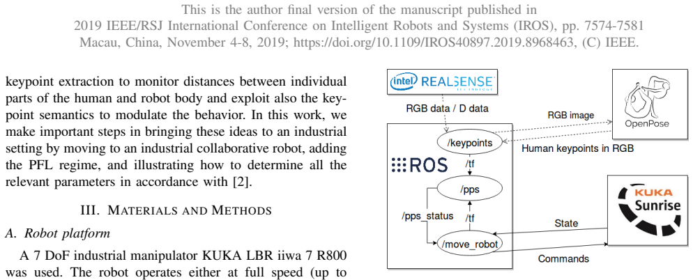
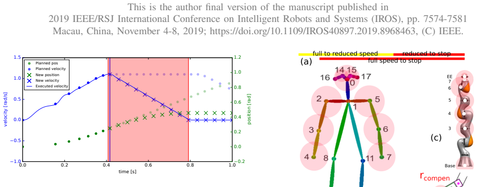
The load-bearing device is the keypoint-pair separation distance matrix, $S^{ij}_{kp} = h^{i}_{\mathrm{compen}} + S^{ij}_p + r^{j}_{\mathrm{compen}}$, in which every human and robot skeleton keypoint is inflated by a compensation sphere ("bounding sphere") so that the discrete tracked points conservatively cover the full body. On top of this sits the protective separation distance $S_p(t_0) = S_h + S_r + S_s + C + Z_d + Z_r$ from the standard, evaluated with fixed worst-case values, and a PFL-derived reduced speed of 0.42 m/s computed from the standard's transient-contact pressure formula $v_{\mathrm{rel,max}} = p_{\mathrm{max}} A / \sqrt{\mu K}$. A trajectory controller stitches a full-speed path to a deceleration-to-reduced-speed path and then to a stop, using maximal joint deceleration and a worst-case reaction time of 0.02 s for the safety decision.
What would settle it
Measure the actual stopping distance of the robot from full speed (1 m/s end-effector) using the controller's claimed deceleration of 1.5 rad/s² and 0.1 s reaction time; if the measured stopping distance exceeds the 0.22 m used in $S_s$, the separation distances in Table II are too small to guarantee no contact.
Extended reading notes
Core claim
The paper claims that the two collaborative regimes prescribed by ISO/TS 15066 — SSM, which keeps a protective separation distance before contact, and PFL, which bounds energy during a contact — can be unified in one application and that this unification outperforms either regime used alone. The best-performing configuration, Scenario 5, lets the robot operate at full speed until any human-robot keypoint pair crosses a reduced-speed threshold (about 1.33 m computed per the standard), then commands the PFL-compliant speed of 0.42 m/s, and issues a full stop only when a head keypoint of the operator crosses a 0.60 m distance from any monitored robot keypoint. With this schedule the mock task took 228 s, compared with 256 s for operating the entire task at the reduced speed and 267 s for a standard zone stop from the robot base. The authors present this as evidence that keypoint-pair distances with body-part-specific thresholds can carry the safety constraints of both regimes while imposing less downtime on the shared task.
Load-bearing premise
The protective separation distance is computed using the robot's average speed during stopping ($v_r = v_{\max}/2$) in the stopping-distance term $S_s = t_s v_r$, an intentional relaxation of the standard's conservative demand; if the robot's deceleration is not uniform or the stopping time is optimistic, the separation distance could be underestimated and contact could occur before the robot stops.
Editorial extensions
If this is right
- A single controller can enforce both SSM and PFL constraints simultaneously, so collaborative cells do not have to sacrifice one regime for the other.
- Keypoint-pair distance monitoring with bounding spheres can replace zone-based light curtains with smaller effective safety footprints.
- Body-part-specific thresholds, especially a stop rule reserved for the head, reduce unnecessary full stops and shorten cycle times.
- The same construction can convert PFL contact limits for any body part into SSM separation distances, so the standard's body-part table can be translated directly into thresholds.
- If RGB-D perception becomes safety-rated, this controller structure can be ported to industrial deployments without further algorithmic changes.
Reading between the lines
- The speed advantage of the head-only stop rule depends on the operator's head being the critical body part; in tasks where hands or torso approach more often, per-part thresholds would need to be tuned from the standard's biomechanical tables to preserve the benefit.
- If a certifier rejects the average-speed approximation and insists on worst-case maximum speed in $S_s$, the computed separation distances grow and the measured time advantage of the combined regimes will shrink; this is a direct, testable consequence of the paper's most relaxed assumption.
- The same bounding-sphere and keypoint-pair machinery could be applied with dynamically computed $S_p$ from instantaneous relative velocity, which the paper identifies as future work; the present measurements of reaction time (0.1 s) and stopping time (0.43 s) provide the inputs such a dynamic controller would need.
Signed reviews
Editorial analysis
A structured set of objections, weighed in public.
Referee Report
Summary. The paper proposes an integrated use of the two ISO/TS 15066 collaborative regimes—speed and separation monitoring (SSM) and power and force limiting (PFL)—in a single mock pick-and-place task. A KUKA LBR iiwa robot is monitored by an Intel RealSense RGB-D camera and OpenPose skeleton extraction; the system computes pairwise distances between robot keypoints and human keypoints and triggers either a reduced-speed state (PFL-compliant) or a full stop. Five scenarios are compared against full-speed and reduced-speed baselines: robot-base zone monitoring (Sc. 1-2), keypoint-pair monitoring with SSM stop (Sc. 3), PFL reduced speed plus SSM stop (Sc. 4), and an additional head-specific stop criterion (Sc. 5). The reported task durations are 154 s (full speed), 256 s (reduced speed), 267 s, 254 s, 257 s, 231 s, and 228 s for Sc. 1-5, respectively; the paper concludes that Sc. 5, which stops only for head keypoints, gives the best collaborative performance. The central safety distances are derived from Eq. (6)-(7) using a non-conservative average-speed stopping distance, and the paper explicitly labels this as a modification of the conservative standard procedure.
Significance. If the safety-related parameter choices can be made rigorous, the paper makes a useful demonstration-level contribution: it shows how the two normative regimes can be embedded in one controller and how keypoint semantics (head versus other body parts) can modulate the response. Strengths include the explicit use of ISO/TS 15066 formulas to derive Sp and the PFL reduced speed (0.42 m/s chosen below the computed 0.50 m/s limit), the concrete robot implementation, and honest acknowledgment that the perception chain is not safety-rated. The performance comparison across seven scenarios is clear and the integrated approach is shown to outperform simple zone monitoring. The main significance is therefore as an experimental proof-of-concept toward a unified SSM+PFL control framework; it does not, as written, deliver a certified-safe system, and the central performance claim depends on fixing the stopping-distance calculation.
major comments (3)
- [Sec. III-G, Eq. (6)-(7)] The stopping-distance term Ss is computed as ts*vr with vr = vmax/2 = 0.5 m/s, yielding Ss = 0.22 m. This is an explicit departure from the conservative worst-case use of the full speed, and the manuscript itself calls it 'a slight alteration of the very conservative demands of [2]'. Because Sp = 1.17 m is then used to set every robot-stop and speed-reduction threshold in Scenarios 3-5, this choice is load-bearing for the paper's safety claim. The average-speed simplification is only valid if the Cartesian speed decreases exactly linearly to zero during ts, which is not established: the controller decelerates joint velocities linearly (Eq. (5)), but the Jacobian makes the Cartesian speed trajectory configuration-dependent, and ts = 0.43 s is inferred from a joint-deceleration setting and a computation-time measurement rather than from a measured end-effector stopping distance. If the true stopping distance from 1 m/s exceeds 0.22 m, all derived thresholds are understated and Scenario 5's time advantage (228 s) is partly a safety shortcut. The authors should either use vmax in Ss (giving Ss = 0.43 m and Sp = 1.38 m) or provide a measured worst-case stopping distance for the actual robot trajectories, and they should recalculate the scenario thresholds and performance numbers under the corrected value.
- [Sec. IV-D, Table III] The performance comparison rests on single reported task-duration values with no variance, confidence intervals, or significance test. The difference between Sc. 4 (231 s) and Sc. 5 (228 s) is only 3 s, and Sc. 2 (254 s) versus Sc. 3 (257 s) also differs by 3 s; without repeated-run statistics it is not possible to conclude that Sc. 5 is reliably the best. The text states that the task was performed 20 times, so reporting means and standard deviations (or per-run scatter) would directly strengthen the central efficiency claim.
- [Sec. III-F, Table I] The human compensation coefficients hcompen are described as 'assigned empirically', but the procedure by which the sphere radii were obtained is not documented. Since the bounding spheres are part of the distance computation that ensures Sp is respected, an underestimation of these radii would reduce the effective protective separation below the standard's requirement. The authors should specify the anthropometric data or body-part assignment used to obtain the listed values, or conservatively inflate them.
minor comments (4)
- [Sec. III-D] The text contains 'breaking behavior' and 'full breaking potential'; these should read 'braking'.
- [Sec. III-G] The entry for Zd is justified with 'see the hcompen values from Subsection III-F: 0 m'; Zd is the sensing-system position uncertainty, not a human-body compensation coefficient, so this justification should be clarified or moved.
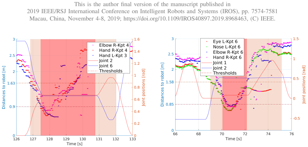
- [Figs. 5 and 6] The threshold values quoted in the captions (reduced speed at 1.63 m, stop at 0.90 m) differ numerically from the Table II entries (1.44/1.49 m and 0.71/0.76 m) for the same scenario family; the relation between these numbers, which include compensation terms, should be stated explicitly in the text.
- [Sec. III-H, Eq. (10)] The numerical substitution for the reduced mass mu would be easier to follow if written out in full before the final vrel,max value is presented.
Circularity Check
No significant circularity: safety thresholds are composed from ISO/TS 15066 parameters and measured robot data; the performance ranking is an experimental outcome, not a fitted prediction.
full rationale
The derivation chain is self-contained. The protective separation distance Sp in Eq. 6 is the ISO/TS 15066 formula, and each term is filled with an externally specified or measured value: Sh uses the standard walking speed and the stated 0.1 s reaction and 0.43 s stopping times; Sr uses vmax = 1 m/s; Ss uses the paper's explicitly labeled average-speed simplification; and C, Zd, Zr are set with stated justifications. The compensation spheres in Table I are derived from the robot model and OpenPose keypoint distribution, not from the outcome variable. The PFL reduced speed of 0.42 m/s is chosen conservatively below the 0.50 m/s limit computed from Eq. A.6 of the standard. The keypoint-pair thresholds in Table II and Eq. 12 are arithmetic sums of these standard-derived distances and compensation coefficients; they are not fitted to the task-duration data. The scenario durations in Table III are measured, so the claim that Scenario 5 performs best is an experimental comparison, not a model prediction forced by construction. The only self-citation is the statement that the SSM part follows up on [18, 30], and that citation is not load-bearing: the safety numbers come from ISO/TS 15066 and measured robot properties, not from those prior papers. The paper itself flags two limitations that bear on validity rather than circularity: the average-speed stopping-distance choice is "a slight alteration of the very conservative demands of [2]", and the pipeline "is not safety-rated" and is "capable of performing a Stop Category 2 only". These are legitimate caveats about whether the thresholds are conservative enough, not evidence that an input has been renamed as an output.
Assumptions & free parameters
free parameters (2)
- Reduced speed (PFL) =
0.42 m/s
- Human compensation coefficients hcompen =
Nose 0.10 m, Neck 0.25 m, Eye 0.10 m, Ear 0.10 m, Arm 0.15 m, Elbow 0.15 m, Wrist 0.15 m (Table I)
assumptions (5)
- domain assumption ISO/TS 15066 formulas for protective separation distance (Eq. 6) and PFL speed limit (Eq. A.6) are valid and applicable to this setup.
- domain assumption Human operator walking speed vh = 1.6 m/s.
- domain assumption OpenPose keypoint detections with confidence >= 0.6 deprojected through depth are accurate enough for distance monitoring.
- ad hoc to paper Using average robot speed vr = vmax/2 in the stopping-distance term Ss is safe.
- ad hoc to paper Bounding spheres with the assigned compensation coefficients cover the human body.
Cite this review
Pith. "Pith review of Safe physical HRI: Toward a unified treatment of speed and separation monitoring together with power and force limiting." pith.science (2026). https://pith.science/paper/G7UYVO4T
@misc{pith2026190803046,
  author       = {Pith},
  title        = {Pith review of: Safe physical HRI: Toward a unified treatment of speed and separation monitoring together with power and force limiting},
  year         = {2026},
  howpublished = {\url{https://pith.science/paper/G7UYVO4T}},
  note         = {Machine review of arXiv:1908.03046}
}
read the original abstract
So-called collaborative robots are a current trend in industrial robotics. However, they still face many problems in practical application such as reduced speed to ascertain their collaborativeness. The standards prescribe two regimes: (i) speed and separation monitoring and (ii) power and force limiting, where the former requires reliable estimation of distances between the robot and human body parts and the latter imposes constraints on the energy absorbed during collisions prior to robot stopping. Following the standards, we deploy the two collaborative regimes in a single application and study the performance in a mock collaborative task under the individual regimes, including transitions between them. Additionally, we compare the performance under "safety zone monitoring" with keypoint pair-wise separation distance assessment relying on an RGB-D sensor and skeleton extraction algorithm to track human body parts in the workspace. Best performance has been achieved in the following setting: robot operates at full speed until a distance threshold between any robot and human body part is crossed; then, reduced robot speed per power and force limiting is triggered. Robot is halted only when the operator's head crosses a predefined distance from selected robot parts. We demonstrate our methodology on a setup combining a KUKA LBR iiwa robot, Intel RealSense RGB-D sensor and OpenPose for human pose estimation.
Figures

Figures from the paper (1 more)
Reference graph
Works this paper leans on
-
[2]
ISO/TS 15066 Robots and robotic devices – Collaborative robots,
“ISO/TS 15066 Robots and robotic devices – Collaborative robots,” International Organization for Standardization, Geneva, CH, Standard, 2016
work page 2016
-
[1]
ISO 10218 Robots and robotic devices – Safety requirements for industrial robots,
“ISO 10218 Robots and robotic devices – Safety requirements for industrial robots,” International Organization for Standardization, Geneva, CH, Standard, 2011
work page 2011
-
[3]
J. Bessler, L. Schaake, C. Bidard, J. H. Buurke, A. E. B. Lassen, K. Nielsen, J. Saenz, and F. Vicentini, “Covr – towards simplified evaluation and validation of collaborative robotics applications across a wide range of domains based on robot safety skills,” in Wearable Robotics: Challenges and Trends , M. C. Carrozza, S. Micera, and J. L. Pons, Eds. Cham...
work page 2019
-
[4]
Physical human-robot interaction,
S. Haddadin and E. Croft, “Physical human-robot interaction,” in Springer Handbook of Robotics , 2nd ed., B. Siciliano and O. Khatib, Eds. Springer, 2016, pp. 1835–1874
work page 2016
-
[5]
Robot collisions: A survey on detection, isolation, and identification,
S. Haddadin, A. De Luca, and A. Albu-Sch ¨affer, “Robot collisions: A survey on detection, isolation, and identification,” IEEE Transactions on Robotics , vol. 33, no. 6, pp. 1292–1312, 2017
work page 2017
-
[6]
Realtime multi-person 2d pose estimation using part affinity fields,
Z. Cao, T. Simon, S.-E. Wei, and Y . Sheikh, “Realtime multi-person 2d pose estimation using part affinity fields,” in CVPR, vol. 1, no. 2, 2017, p. 7
work page 2017
-
[7]
Deepercut: A deeper, stronger, and faster multi-person pose estimation model,
E. Insafutdinov, L. Pishchulin, B. Andres, M. Andriluka, and B. Schiele, “Deepercut: A deeper, stronger, and faster multi-person pose estimation model,” in European Conference on Computer Vision . Springer, 2016, pp. 34–50
work page 2016
-
[8]
DensePose: Dense Human Pose Estimation In The Wild
R. A. G ¨uler, N. Neverova, and I. Kokkinos, “Densepose: Dense human pose estimation in the wild,” arXiv preprint arXiv:1802.00434 , 2018
work page Pith review arXiv 2018
Show all 37 references
-
[9]
Device- free human sensing and localization in collaborative human–robot workspaces: A case study,
S. Savazzi, V . Rampa, F. Vicentini, and M. Giussani, “Device- free human sensing and localization in collaborative human–robot workspaces: A case study,” IEEE Sensors Journal , vol. 16, no. 5, pp. 1253–1264, 2016
2016
-
[10]
A depth space approach to human-robot collision avoidance,
F. Flacco, T. Kr ¨oger, A. De Luca, and O. Khatib, “A depth space approach to human-robot collision avoidance,” in Robotics and Au- tomation (ICRA), 2012 IEEE International Conference on . IEEE, 2012, pp. 338–345
2012
-
[11]
A depth space approach for evaluating distance to objects,
F. Flacco, T. Kroeger, A. De Luca, and O. Khatib, “A depth space approach for evaluating distance to objects,” Journal of Intelligent & Robotic Systems , vol. 80, p. 7, 2015
2015
-
[12]
3d collision detection: a survey,
P. Jim ´enez, F. Thomas, and C. Torras, “3d collision detection: a survey,” Computers & Graphics , vol. 25, no. 2, pp. 269–285, 2001
2001
-
[13]
A computationally efficient safety assessment for collaborative robotics applications,
M. P. Polverini, A. M. Zanchettin, and P. Rocco, “A computationally efficient safety assessment for collaborative robotics applications,” Robotics and Computer-Integrated Manufacturing , vol. 46, pp. 25– 37, 2017
2017
-
[14]
Safety in human-robot collaborative manufacturing environments: Metrics and control,
A. M. Zanchettin, N. M. Ceriani, P. Rocco, H. Ding, and B. Matthias, “Safety in human-robot collaborative manufacturing environments: Metrics and control,” IEEE Transactions on Automation Science and Engineering, vol. 13, no. 2, pp. 882–893, 2016
2016
-
[15]
Kinetostatic danger field-a novel safety assessment for human-robot interaction,
B. Lacevic and P. Rocco, “Kinetostatic danger field-a novel safety assessment for human-robot interaction,” in Intelligent Robots and Systems (IROS), 2010 IEEE/RSJ International Conference on . IEEE, 2010, pp. 2169–2174
2010
-
[16]
Safeguarding a mobile manipulator using dynamic safety fields,
V . Magnanimo, S. Walther, L. Tecchia, C. Natale, and T. Guhl, “Safeguarding a mobile manipulator using dynamic safety fields,” in Intelligent Robots and Systems (IROS), 2016 IEEE/RSJ International Conference on. IEEE, 2016, pp. 2972–2977
2016
-
[17]
Peripersonal space and margin of safety around the body: learning tactile-visual associations in a humanoid robot with artificial skin,
A. Roncone, M. Hoffmann, U. Pattacini, L. Fadiga, and G. Metta, “Peripersonal space and margin of safety around the body: learning tactile-visual associations in a humanoid robot with artificial skin,” PLoS ONE , vol. 11, no. 10, p. e0163713, 2016
2016
-
[18]
Compact real-time avoidance on a humanoid robot for human-robot interaction,
D. H. P. Nguyen, M. Hoffmann, A. Roncone, U. Pattacini, and G. Metta, “Compact real-time avoidance on a humanoid robot for human-robot interaction,” in Proceedings of the 2018 ACM/IEEE International Conference on Human-Robot Interaction . ACM, 2018, pp. 416–424
2018
-
[19]
Randomized kinodynamic planning,
S. LaValle and J. Kuffner, “Randomized kinodynamic planning,” Int. Journal of Robotics Research , vol. 20, no. 5, pp. 378–400, 2001
2001
-
[20]
Real-time obstacle avoidance for manipulators and mobile robots,
O. Khatib, “Real-time obstacle avoidance for manipulators and mobile robots,” The international journal of robotics research , vol. 5, no. 1, pp. 90–98, 1986
1986
-
[21]
Elastic strips: A framework for motion generation in human environments,
O. Brock and O. Khatib, “Elastic strips: A framework for motion generation in human environments,” The International Journal of Robotics Research, vol. 21, no. 12, pp. 1031–1052, 2002
2002
-
[22]
Motion planning in dynamic environments using velocity obstacles,
P. Fiorini and Z. Shiller, “Motion planning in dynamic environments using velocity obstacles,” The International Journal of Robotics Re- search, vol. 17, no. 7, pp. 760–772, 1998
1998
-
[23]
Perceiving guaranteed continuously collision- free robot trajectories in an unknown and unpredictable environment,
R. Vatcha and J. Xiao, “Perceiving guaranteed continuously collision- free robot trajectories in an unknown and unpredictable environment,” in Intelligent Robots and Systems, 2009. IROS 2009. IEEE/RSJ Inter- national Conference on . IEEE, 2009, pp. 1433–1438
2009
-
[24]
Integrated control for phri: Collision avoid- ance, detection, reaction and collaboration,
A. De Luca and F. Flacco, “Integrated control for phri: Collision avoid- ance, detection, reaction and collaboration,” in Biomedical Robotics and Biomechatronics (BioRob), 2012 4th IEEE RAS & EMBS Inter- national Conference on . IEEE, 2012, pp. 288–295
2012
-
[25]
Performance metrics of speed and separation monitoring in shared workspaces,
J. A. Marvel, “Performance metrics of speed and separation monitoring in shared workspaces,” IEEE Transactions on Automation Science and Engineering, vol. 10, no. 2, pp. 405–414, 2013
2013
-
[26]
Computation of safe path velocity for collaborative robots,
C. Sloth and H. G. Petersen, “Computation of safe path velocity for collaborative robots,” in 2018 IEEE/RSJ International Conference on Intelligent Robots and Systems (IROS) . IEEE, 2018, pp. 6142–6148
2018
-
[27]
Safety map: A unified representation for biomechanics impact data and robot instantaneous dynamic properties,
M. Nico, M. Hamad, M. Becker, A. G. Marin, and S. Haddadin, “Safety map: A unified representation for biomechanics impact data and robot instantaneous dynamic properties,” IEEE Robotics and Automation Letters, vol. 3, no. 3, pp. 1880–1887, 2018
2018
-
[28]
Control of robots sharing their workspace with humans: an energetic approach to safety,
A. Meguenani, V . Padois, and P. Bidaud, “Control of robots sharing their workspace with humans: an energetic approach to safety,” in2015 IEEE/RSJ International Conference on Intelligent Robots and Systems (IROS). IEEE, 2015, pp. 4678–4684
2015
-
[29]
A pre-collision control strategy for human-robot interaction based on dissipated energy in potential inelastic impacts,
R. Rossi, M. P. Polverini, A. M. Zanchettin, and P. Rocco, “A pre-collision control strategy for human-robot interaction based on dissipated energy in potential inelastic impacts,” in 2015 IEEE/RSJ International Conference on Intelligent Robots and Systems (IROS) . IEEE, 2015,...
2015
-
[30]
Toward safe separation distance monitoring from RGB-D sensors in human-robot interaction,
P. Svarny, Z. Straka, and M. Hoffmann, “Toward safe separation distance monitoring from RGB-D sensors in human-robot interaction,” in International PhD Conference on Safe and Social Robotics (SSR- 2018), 2018, pp. 11–14
2018
-
[31]
librealsense,
Intel, “librealsense,” https://github.com/IntelRealSense/librealsense, 2018, version 2.17.1; Accessed: 2019-02-24
2018
-
[32]
Reducing the barrier to entry of complex robotic software: a MoveIt! case study,
D. Coleman, I. Sucan, S. Chitta, and N. Correll, “Reducing the barrier to entry of complex robotic software: a MoveIt! case study,” arXiv preprint arXiv:1404.3785, 2014
2014 arXiv
-
[33]
Naive control of the double integrator,
V . G. Rao and D. S. Bernstein, “Naive control of the double integrator,” IEEE Control Systems Magazine , vol. 21, no. 5, pp. 86–97, Oct. 2001
2001
-
[34]
The OpenCV Library,
G. Bradski, “The OpenCV Library,” Dr . Dobb’s Journal of Software Tools, 2000
2000
-
[35]
OpenPose: realtime multi-person 2D pose estimation using Part Affinity Fields,
Z. Cao, G. Hidalgo, T. Simon, S.-E. Wei, and Y . Sheikh, “OpenPose: realtime multi-person 2D pose estimation using Part Affinity Fields,” in arXiv preprint arXiv:1812.08008 , 2018
2018 arXiv
-
[36]
Real-time computation of distance to dynamic obstacles with multiple depth sensors,
F. Fabrizio and A. De Luca, “Real-time computation of distance to dynamic obstacles with multiple depth sensors,” IEEE Robotics and Automation Letters, vol. 2, no. 1, pp. 56–63, 2017
2017
-
[37]
Trajectory generation algorithm for safe human-robot collaboration based on multiple depth sensor measurements,
M. Ragaglia, A. M. Zanchettin, and P. Rocco, “Trajectory generation algorithm for safe human-robot collaboration based on multiple depth sensor measurements,” Mechatronics, 2018
2018
Reviewed August 14, 2026 · model on record in the stance chip above.
Discussion (0). Continue with ORCID to comment.