REVIEW 4 major objections 6 minor 27 references
Robust Translational Force Control of Multi-Rotor UAV for Precise Acceleration Tracking
T0 review · 4 major / 6 minor · reviewed 2026-08-14 · deepseek-v4-flash
Pith's one-line read Computing thrust from measured current roll and pitch, rather than desired attitude, keeps a multirotor's vertical acceleration accurate even when its moment of inertia is large.
desk verdict A genuinely useful converter fix (thrust from measured attitude) wrapped in a standard DOB package, but the key comparison is only a simulation that shares the model's own delay assumptions. read the letter →
The pith
A machine-rendered reading of the paper's core claim, the machinery that carries it, and where it could break.
The reading
What carries the argument
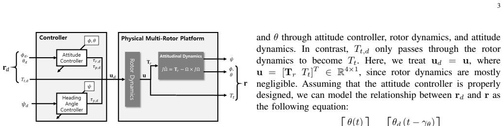
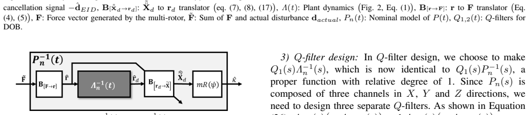
The load-bearing object is the command converter formed by Equations (7), (8), and (17): desired roll and pitch come from the usual kinematic inversion, but the total thrust is $T_{t,d}=-m\tilde{\ddot{z}}_d(t)/(\cos\varphi(t)\cos\theta(t))$, with $\varphi(t)$ and $\theta(t)$ measured from the IMU rather than taken from the delayed attitude command. That replacement is what aligns the vertical component of thrust with the current tilt, so the vertical channel no longer waits for the attitude delay. The second load-bearing mechanism is the disturbance observer—a loop that estimates the equivalent input disturbance from measured acceleration and cancels it—whose nominal model $P_n=\Lambda_n(s)$ is built from the attitude-loop transfer functions and the instantaneous thrust transfer function, with Q-filters chosen by structured singular value analysis.
What would settle it
Command a vertical acceleration step, or a sinusoid with period comparable to the attitude delay, while the multirotor is tilted by a lateral acceleration command on a platform whose moment of inertia has been increased by an added mass. If the $z$-axis tracking error grows as the vertical command gets faster or as the added mass increases, the ratio assumption $\tilde{\ddot{z}}_d(t)/\tilde{\ddot{z}}_d(t-\gamma_h)\approx1$ is the failing premise; if it stays flat, the pure-delay model of the attitude loop is the premise to test.
Extended reading notes
Core claim
On the paper's own terms, the central discovery is that replacing the desired roll and pitch in the thrust command by the measured current roll and pitch turns the multirotor's translational input–output relation into $\tilde{\ddot{X}}(t)\approx[\tilde{\ddot{x}}_d(t-\gamma_h),\,\tilde{\ddot{y}}_d(t-\gamma_h),\,\tilde{\ddot{z}}_d(t)]$ (Equation (18)): the vertical channel tracks its command without delay, while the horizontal channels carry only the common attitude delay $\gamma_h$. With the standard inversion of Equation (9), the thrust is computed from the desired attitude, so the actual attitude delay makes the vertical thrust compensation wrong and degrades the $z$-channel; the contamination then hurts the $x,y$ channels when an outer position loop keeps correcting. The paper further claims that the nominal model $\Lambda_n(s)$ needed for the new converter can serve as the DOB plant, and that $\mu$-analysis gives a less conservative stability margin ($\tau_1>0.12$, $\tau_2>0.09$) than a lumped small-gain bound. Flight experiments are reported to show the claimed vertical-channel accuracy and reduction of wind-induced position error from about 1 m to about 0.3 m.
Load-bearing premise
The analysis assumes the actual roll and pitch are just the desired roll and pitch delayed by the same time-varying lag $\gamma_h$, and that the desired vertical acceleration barely changes during that lag; if the attitude response is not a pure delay or the vertical command changes abruptly, the claimed separation between vertical and horizontal tracking breaks down.
Editorial extensions
If this is right
- For a symmetric multirotor whose roll and pitch delays are equal, the vertical acceleration channel becomes independent of the attitude delay, so increasing the moment of inertia no longer degrades $z$-axis acceleration tracking.
- The horizontal channels still lag by $\gamma_h$, so lateral acceleration commands are not tracked without delay; the converter's benefit is preventing vertical error from coupling back into them through the outer position loop.
- Because the disturbance observer estimates the equivalent input force, external translational disturbances such as wind, tether pulls, or added payload weight can be cancelled without changing the position controller.
- The $\mu$-analysis stability condition permits faster Q-filters than a small-gain analysis would, allowing the DOB to reject disturbances at higher frequencies than the earlier preliminary design.
- In the reported tests, actual three-dimensional acceleration follows operator commands, and wind-disturbance position error drops from about 1 m to about 0.3 m when the DOB is on.
Reading between the lines
- A direct test of the ratio assumption in Equation (18) would be to command fast vertical oscillations; if $z$-tracking degrades with frequency, that assumption, not the converter structure, is the limit.
- For an asymmetric airframe the equal-delay assumption $\gamma_\phi=\gamma_\theta=\gamma_h$ may fail; using separately measured roll and pitch in Equation (17) is still meaningful, but the clean decoupling of Equation (18) would no longer follow.
- The equivalent-input-disturbance formulation suggests the same loop can absorb slowly varying payload weight as a disturbance, which would let a delivery platform keep its tuned position gains when cargo mass changes.
Signed reviews
Editorial analysis
A structured set of objections, weighed in public.
Referee Report
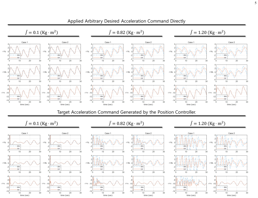
Summary. The paper proposes a translational force control method for multi-rotor UAVs that combines a new acceleration-to-attitude/thrust converter with a disturbance observer (DOB). The converter, defined by Eqs. (7), (8) and (17), uses measured current roll and pitch in the thrust command. Under the assumption that actual attitude equals the desired attitude delayed by a time-varying factor (Eq. (10)), the paper derives the approximate input-output relation (Eq. (18)): horizontal acceleration channels are delayed by gamma_h while the vertical channel is undelayed, supposedly eliminating the vertical-channel degradation seen with the standard converter (Eq. (9)). A DOB is then designed, with the nominal model P_n(s) built from the attitude closed-loop transfer functions and a unity thrust channel, and its Q-filters are tuned via mu-analysis. Stability analysis models uncertainties in gain, moment of inertia, and time delay. Validation is reported through simulation (Fig. 3) comparing the proposed and standard converters under varying MOI, flight tests of acceleration tracking (Fig. 10), and DOB simulations and experiments including a tether disturbance and a wind fan.
Significance. If the central claims are correct, the converter would be a practically useful improvement for multi-rotors with slow attitude dynamics (large moment of inertia), and the systematic mu-analysis-based DOB design would strengthen confidence in the closed-loop system. The paper contains a clear first-principles derivation of the converter, explicitly identifies the assumptions it uses, and provides reproducible-looking simulation and experimental demonstrations. The use of measured current attitude in the thrust command is a clever and simple fix for the asynchronous realization of attitude and thrust. However, the claimed advantage over the standard converter rests on a simulation that may share the same model assumptions as the derivation, and the flight experiments do not include the large-MOI condition or a baseline comparison. The DOB nominal model appears inconsistent with the pure-delay model used to derive the converter, which undermines the robustness analysis. These issues must be resolved before the main contribution can be accepted.
major comments (4)
- [Section III-B, Eqs. (26)-(29)] The nominal model P_n(s)=Λ_n(s) is not consistent with the model used to derive the converter. Equation (10) models the attitude channels as pure time delays, and Equation (18) is derived from that delay model; however, Λ_n(s) in Equation (26) is a second-order rational transfer function. The claim that Equation (28) is 'a detailed representation' of Equation (10) is therefore unsupported, and the DOB design uses a nominal model that does not match the plant model on which the converter's performance claim rests. The μ-analysis in Equation (34), with uncertainties on K_j, J_j, and δ_j, does not cover this structural mismatch.
- [Section V, Fig. 3 and Fig. 10] The only direct comparison of the proposed converter (Eq. (17)) with the standard converter (Eq. (9)) is the simulation in Fig. 3, whose plant model is not described in the manuscript. If the simulation uses the same pure-delay model as the derivation, it cannot independently validate the decoupling claim. The flight experiment in Fig. 10 demonstrates acceleration tracking on one platform but includes no Case-1 baseline, no added-inertia condition, and no repeated trials, so the large-MOI advantage claimed in the abstract is not empirically supported.
- [Section II, Eq. (18)] The approximation tilde_z_d(t)/tilde_z_d(t-γ_h)≈1 is not quantified. The paper states it is valid 'except in situations where the change in target vertical acceleration is abnormally large and rapid,' but does not provide a bound on the resulting tracking error or a characterization of the region of validity. This approximation is central to the claimed decoupling in Eq. (18); without a quantitative bound, the guaranteed performance of the converter is unclear.
- [Section IV, Eqs. (33)-(47)] The μ-analysis is performed on a diagonal model P_j(s) with independent uncertainties in each channel. The actual plant, as described by Eq. (12) and Eq. (18), contains coupling between channels and a ratio term that is nonlinear and time-varying; these are not represented in the uncertainty set Δ_j. Consequently, the robust stability condition in Eq. (46) does not necessarily guarantee stability for the full nonlinear system, and the stated stability margins may be optimistic.
minor comments (6)
- [Introduction, Section numbering] The organizational statements in the introduction are off by one: the text says 'In Section II, we discuss the mathematical model' but the model appears in Section I, and 'Section III deals with the force control' but that material is in Section II.
- [Abstract / Note to Practitioners] The 'Note to Practitioners' block immediately repeats the word 'Abstract' after the heading; this should be removed or reformatted.
- [Section II, solution candidate 2] The sentence 'From the flight results using Equation (17) in Fig. 3' refers to a simulation figure, not flight results; the wording should be corrected to avoid confusion.
- [Section IV, Eq. (41)] The procedure for determining Wδ,j(s) from 'a large amount of actual experimental data' is not described; please provide the data, a reference, or a more detailed explanation of how the bound in Eq. (41) was obtained.
- [Section V, Fig. 12] The comparison between estimated and measured disturbance in Fig. 12 is only qualitative; adding a quantitative metric such as RMS error would strengthen the validation of the DOB estimator.
- [Section V, wind experiment] The wind disturbance experiment reports only single position-error values (about 1 m DOB-off versus about 0.3 m DOB-on); providing time-series plots or repeated trials would clarify trial-to-trial variability and support the claimed improvement.
Circularity Check
No significant circularity: the converter result is an algebraic consequence of an explicit delay model, and the DOB nominal model is constructed from the same model rather than fitted to the claimed response.
full rationale
The central derivation (Eqs. (7), (8) and (17) leading to Eq. (18)) does not reduce to its inputs by construction. The paper first states the delay model Eq. (10): r(t)≈[θd(t−γθ), φd(t−γφ), Tt,d(t)]^T, and derives from the plant equation (5) the delayed response Eq. (12) when using the naive thrust command Eq. (9). The proposed thrust command Eq. (17) substitutes the measured attitude for the desired attitude in the denominator of Tt,d. Substituting Eq. (17) into Eq. (11) gives exactly m˜¨X = m[tanθ(t), −tanφ(t)/cosθ(t), 1]^T ˜¨zd(t), and using Eq. (15) together with γφ=γθ=γh produces Eq. (18). This is an algebraic consequence of the stated assumptions, not a fitted quantity or a self-citation; the z-channel result ˜¨z(t)=˜¨zd(t) is a deliberate feedback-linearizing choice rather than a prediction asserted independently of the model. The DOB nominal model Pn=Λn is likewise constructed from the same attitude-loop transfer function used in the model (Eqs. (26)-(29)), which is standard DOB practice. The µ-analysis uses explicit uncertainty bounds (K, J, δ) and computes τ thresholds; no parameter is fitted to reproduce a claimed output. The only self-citation [18] is used for the preliminary DOB structure and an SGT comparison, not as load-bearing evidence for the new converter. The Fig. 3 simulation is model-consistent rather than an independent falsification of the pure-delay premise, and the flight test lacks a baseline with Eq. (9); these are validation-strength limitations, but they are not circularity because the derivation is self-contained and does not assume Eq. (18) as an input.
Assumptions & free parameters
free parameters (5)
- Wδ,j(s) envelope coefficients =
(2.015 s^3 + 52.88 s^2 + 431.6 s + 0.415)/(s^3 + 36.7 s^2 + 606.8 s + 3521)
- Uncertainty bounds (max|δj|, max|JΔ,j|, max|KΔ,j|) =
0.12, 0.3, 0.1
- Q-filter time constants τ1, τ2 =
0.15, 0.12
- Attitude PD gains Pφ,θ, Dφ,θ =
3, 1
- Q-filter damping ζ =
0.707
assumptions (8)
- standard math Rigid body dynamics of the multi-rotor (Eq. 1) with mass m, rotation matrix R(q), thrust vector Tt, and gravity.
- domain assumption Simplified attitude dynamics J q_ddot = Tr (Eq. 2), neglecting Coriolis terms and assuming small roll/pitch.
- domain assumption Yaw angle is held at zero by an independent controller.
- domain assumption Rotor dynamics are negligible, so Λn,t(s) = 1 (Eq. 27).
- ad hoc to paper Actual attitude tracks desired attitude with pure time-varying delays γφ and γθ, and γφ = γθ = γh (Eq. 10 and following text).
- ad hoc to paper Ratio approximation ~zd(t)/~zd(t-γh) ≈ 1.
- domain assumption Uncertainty structure P_j(s) = K_j Λn,j(s) e^{-δ_j s} with real parametric and complex time-delay uncertainties (Eq. 34).
- domain assumption Equivalent-input-disturbance concept for the DOB (Section IV.B).
Cite this review
Pith. "Pith review of Robust Translational Force Control of Multi-Rotor UAV for Precise Acceleration Tracking." pith.science (2026). https://pith.science/paper/77JXT4RR
@misc{pith2026190805007,
  author       = {Pith},
  title        = {Pith review of: Robust Translational Force Control of Multi-Rotor UAV for Precise Acceleration Tracking},
  year         = {2026},
  howpublished = {\url{https://pith.science/paper/77JXT4RR}},
  note         = {Machine review of arXiv:1908.05007}
}
read the original abstract
In this paper, we introduce a translational force control method with disturbance observer (DOB)-based force disturbance cancellation for precise three-dimensional acceleration control of a multi-rotor UAV. The acceleration control of the multi-rotor requires conversion of the desired acceleration signal to the desired roll, pitch, and total thrust. But because the attitude dynamics and the thrust dynamics are different, simple kinematic signal conversion without consideration of those difference can cause serious performance degradation in acceleration tracking. Unlike most existing translational force control techniques that are based on such simple inversion, our new method allows controlling the acceleration of the multi-rotor more precisely by considering the dynamics of the multi-rotor during the kinematic inversion. By combining the DOB with the translational force system that includes the improved conversion technique, we achieve robustness with respect to the external force disturbances that hinders the accurate acceleration control. mu-analysis is performed to ensure the robust stability of the overall closed-loop system, considering the combined effect of various possible model uncertainties. Both simulation and experiment are conducted to validate the proposed technique, which confirms the satisfactory performance to track the desired acceleration of the multi-rotor.
Figures

Figures from the paper (8 more)



Reference graph
Works this paper leans on
-
[1]
Quadrotor dynamics and control rev 0.1,
R. Beard, “Quadrotor dynamics and control rev 0.1,” 2008
work page 2008
-
[2]
O. Mofid and S. Mobayen, “Adaptive sliding mode control for finite- time stability of quad-rotor uavs with parametric uncertainties,” ISA transactions, vol. 72, pp. 1–14, 2018
work page 2018
-
[3]
Trajectory tracking control design with command-filtered compensation for a quadrotor,
Z. Zuo, “Trajectory tracking control design with command-filtered compensation for a quadrotor,”IET control theory & applications, vol. 4, no. 11, pp. 2343–2355, 2010
work page 2010
-
[4]
B. Zhao, B. Xian, Y . Zhang, and X. Zhang, “Nonlinear robust adaptive tracking control of a quadrotor uav via immersion and invariance methodology,” IEEE Transactions on Industrial Electronics, vol. 62, no. 5, pp. 2891–2902, 2015
work page 2015
-
[5]
S. Mobayen and F. Tchier, “An lmi approach to adaptive robust tracker design for uncertain nonlinear systems with time-delays and input nonlinearities,” Nonlinear Dynamics, vol. 85, no. 3, pp. 1965–1978, 2016
work page 1965
-
[6]
——, “Composite nonlinear feedback integral sliding mode tracker design for uncertain switched systems with input saturation,” Communications in Nonlinear Science and Numerical Simulation, vol. 65, pp. 173–184, 2018
work page 2018
-
[7]
Motion control for advanced mechatronics,
K. Ohnishi, M. Shibata, and T. Murakami, “Motion control for advanced mechatronics,” IEEE/ASME transactions on mechatronics, vol. 1, no. 1, pp. 56–67, 1996
work page 1996
-
[8]
Backstepping- based attitude control for a quadrotor uav using nonlinear disturbance observer,
W. Qingtong, W. Honglin, W. Qingxian, and C. Mou, “Backstepping- based attitude control for a quadrotor uav using nonlinear disturbance observer,” in 34th Chinese Control Conference (CCC). IEEE, 2015, pp. 771–776
work page 2015
Show all 27 references
-
[9]
Disturbance observer and nonlinear damping control for fast track- ing quadrotor vehicles,
A. T. Salton, D. Eckhard, J. V . Flores, G. Fernandes, and G. Azevedo, “Disturbance observer and nonlinear damping control for fast track- ing quadrotor vehicles,” in IEEE Conference on Control Applications (CCA). IEEE, 2016, pp. 705–710
2016
-
[10]
Evaluation of acceleration-based disturbance observation for multicopter control,
T. Tomic, “Evaluation of acceleration-based disturbance observation for multicopter control,” in European Control Conference (ECC). IEEE, 2014, pp. 2937–2944
2014
-
[11]
Nonlinear disturbance observer based robust attitude tracking controller for quadrotor uavs,
K. Lee, J. Back, and I. Choy, “Nonlinear disturbance observer based robust attitude tracking controller for quadrotor uavs,” International Journal of Control, Automation and Systems, vol. 12, no. 6, pp. 1266– 1275, 2014
2014
-
[12]
Trajectory tracking control for an indoor quadrotor uav based on the disturbance observer,
H. Wang and M. Chen, “Trajectory tracking control for an indoor quadrotor uav based on the disturbance observer,” Transactions of the Institute of Measurement and Control, vol. 38, no. 6, pp. 675–692, 2016
2016
-
[13]
Time domain disturbance observer based control of a quadrotor unmanned aerial vehicle,
A. Aboudonia, R. Rashad, and A. El-Badawy, “Time domain disturbance observer based control of a quadrotor unmanned aerial vehicle,” in XXV International Conference on Information, Communication and Automation Technologies (ICAT). IEEE, 2015, pp. 1–6
2015
-
[14]
Robust trajectory tracking for underactuated vtol aerial vehicles: Extended for adaptive disturbance compensation,
P. Castaldi, N. Mimmo, R. Naldi, and L. Marconi, “Robust trajectory tracking for underactuated vtol aerial vehicles: Extended for adaptive disturbance compensation,” IFAC Proceedings V olumes, vol. 47, no. 3, pp. 3184–3189, 2014
2014
-
[15]
Robust control of an equipment-added multirotor using disturbance observer,
S. Kim, S. Choi, H. Kim, J. Shin, H. Shim, and H. J. Kim, “Robust control of an equipment-added multirotor using disturbance observer,” IEEE Transactions on Control Systems Technology, vol. 26, no. 4, 2018
2018
-
[16]
Comparison of various quaternion-based control methods applied to quadrotor with disturbance observer and position estimator,
A. Chovancov ´a, T. Fico, P. Hubinsk `y, and F. Ducho ˇn, “Comparison of various quaternion-based control methods applied to quadrotor with disturbance observer and position estimator,” Robotics and Autonomous Systems, vol. 79, pp. 87–98, 2016
2016
-
[17]
High-performance trajectory tracking control of a quadrotor with disturbance observer,
W. Dong, G.-Y . Gu, X. Zhu, and H. Ding, “High-performance trajectory tracking control of a quadrotor with disturbance observer,” Sensors and Actuators A: Physical, vol. 211, pp. 67–77, 2014
2014
-
[18]
Robust acceleration control of a hexarotor uav with a disturbance observer,
S. J. Lee, S. Kim, K. H. Johansson, and H. J. Kim, “Robust acceleration control of a hexarotor uav with a disturbance observer,” in IEEE 55th Conference on Decision and Control (CDC). IEEE, 2016, pp. 4166– 4171
2016
-
[19]
Trajectory tracking control of multirotors from modelling to experiments: A survey,
H. Lee and H. J. Kim, “Trajectory tracking control of multirotors from modelling to experiments: A survey,” International Journal of Control, Automation and Systems, vol. 15, no. 1, pp. 281–292, 2017
2017
-
[20]
Im- proving disturbance-rejection performance based on an equivalent-input- disturbance approach,
J.-H. She, M. Fang, Y . Ohyama, H. Hashimoto, and M. Wu, “Im- proving disturbance-rejection performance based on an equivalent-input- disturbance approach,” IEEE Transactions on Industrial Electronics, vol. 55, no. 1, pp. 380–389, 2008
2008
-
[21]
Disturbance observer and feedfor- ward design for a high-speed direct-drive positioning table,
C. J. Kempf and S. Kobayashi, “Disturbance observer and feedfor- ward design for a high-speed direct-drive positioning table,” IEEE Transactions on control systems Technology, vol. 7, no. 5, pp. 513–526, 1999
1999
-
[22]
Fielding, A
C. Fielding, A. Varga, S. Bennani, and M. Selier, Advanced techniques for clearance of flight control laws. Springer Science & Business Media, 2002, vol. 283
2002
-
[23]
Analysis the robustness of control systems based on disturbance observer,
E. Sariyildiz and K. Ohnishi, “Analysis the robustness of control systems based on disturbance observer,”International Journal of Control, vol. 86, no. 10, pp. 1733–1743, 2013
2013
-
[24]
A robust con- trol approach for hydraulic excavators using µ-synthesis,
S. Kim, J. Park, S. Kang, P. Y . Kim, and H. J. Kim, “A robust con- trol approach for hydraulic excavators using µ-synthesis,” International Journal of Control, Automation and Systems, vol. 16, no. 4, pp. 1615– 1628, 2018
2018
-
[25]
Analysis of feedback systems with structured uncertainties,
J. Doyle, “Analysis of feedback systems with structured uncertainties,” in IEE Proceedings D-Control Theory and Applications, vol. 129, no. 6. IET, 1982, pp. 242–250
1982
-
[26]
Zhou and J
K. Zhou and J. C. Doyle, Essentials of robust control. Prentice hall Upper Saddle River, NJ, 1998, vol. 104
1998
-
[27]
Skogestad and I
S. Skogestad and I. Postlethwaite, Multivariable feedback control: analysis and design. Wiley New York, 2007, vol. 2. Seung Jae Lee (S’17) received the B.S. degree in mechanical engineering from Hanyang University, Seoul, Korea in 2014, and the M.S. degree in mechanical and ae...
2007
Reviewed August 14, 2026 · model on record in the stance chip above.
Discussion (0). Continue with ORCID to comment.