REVIEW 2 major objections 5 minor 15 references
Matching-based Depth Camera and Mirrors for 3D Reconstruction
T0 review · 2 major / 5 minor · reviewed 2026-08-14 · deepseek-v4-flash
Pith's one-line read A single matching-based depth camera with two or more mirrors can reconstruct a 3D object point cloud with fitting errors below one centimeter.
desk verdict A plausible low-cost mirror rig for 3D reconstruction whose central depth-in-mirror assumption is still only indirectly supported; worth a referee, but the evaluation overreaches. read the letter →
The pith
A machine-rendered reading of the paper's core claim, the machinery that carries it, and where it could break.
The reading
What carries the argument
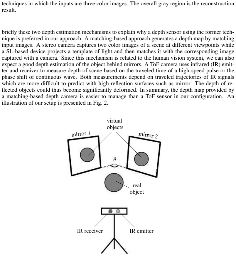
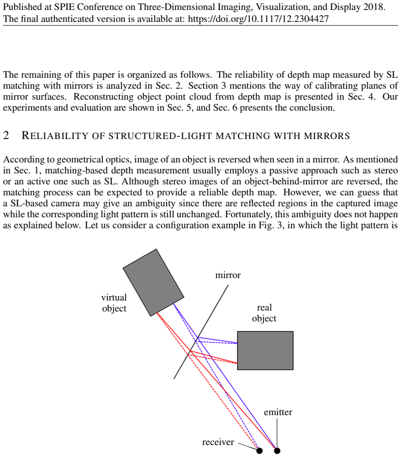
The load-bearing object is the mirror-as-virtual-depth-camera mapping. Each mirror plane is estimated from 3D coordinates of markers placed on it, using RANSAC combined with an SVD fit, so the only calibration needed is the depth camera's internal matrix. For every depth pixel assigned to a reflected part of the object, the pixel is reprojected by $[X,Y,Z]^\top = Z\,\mathrm{diag}(f_x^{-1}, f_y^{-1}, 1)[x-c_x, y-c_y, 1]^\top$ and then reflected through the plane, which is equivalent to viewing the object from a virtual camera behind the mirror. The mirror's viability for matching-based depth is carried by the double-reflection symmetry: the structured-light pattern is flipped once by the mirror and flipped back on the return path, so matching is unaffected. Algorithm 2 inverts the same logic, carving voxels whose projected depth disagrees with measured depth in any real or reflected view.
What would settle it
Place a known flat target in front of a mirror and read the depth values on its reflected region: if the reported depth follows the mirror plane rather than the virtual target, the reflection step in Algorithm 1 is invalid. A direct accuracy check is to reconstruct a sphere from mirror-only pixels with the mirrors near the reported optimum of $120^\circ$ and compare the fitted radius to the manually measured radius; a deviation above one centimeter would contradict the sub-centimeter error claim.
Extended reading notes
Core claim
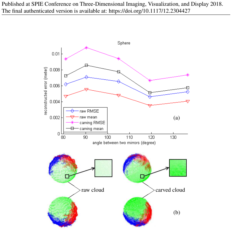
The central claim is that a structured-light depth camera can be used as several synchronized depth cameras at once by placing mirrors around the object: each mirror defines a virtual viewpoint, and the depth value at a pixel showing a reflection is interpreted as the distance to the virtual object behind the mirror. The key reason this works is that the projected light pattern is reflected twice on its path from emitter to receiver, so the pattern's order is restored and matching-based depth estimation remains reliable. Reconstruction then becomes a simple geometric operation: reproject each object pixel into 3D and, when the point lies in a mirror region behind the mirror plane, reflect it across that plane using $P_r = P - 2\|\hat n\|^{-1}(P^\top \hat n + d)\hat n$. The paper reports that a sphere reconstructed in this way had fitted errors below 1 centimeter, with the lowest errors near a $120^\circ$ angle between mirrors, and demonstrates the same pipeline on a cylinder and a human body. For static scenes, a space-carving algorithm keeps or removes voxels by comparing projected depth in real and reflected views, yielding a denser cloud at the cost of larger errors.
Load-bearing premise
The whole reconstruction rests on the assumption that when a depth pixel shows an object reflected in a mirror, the reported depth is the distance to the virtual object behind the mirror, not the distance to the mirror surface itself.
Editorial extensions
If this is right
- Moving objects can be reconstructed without a multi-camera synchronization protocol, since every view comes from the same sensor at the same time.
- The hardware cost of a multi-view 3D reconstruction system is reduced to one consumer depth camera plus two mirrors.
- The raw point-cloud algorithm processes a frame in about 0.2 seconds in non-optimized code, making real-time dynamic capture feasible.
- The angle between mirrors changes accuracy, with the lowest sphere-fitting errors near $120^\circ$ in these experiments, so the angle can be tuned for a given setup.
- For static objects, the space-carving variant produces a denser cloud, but with larger fitting errors than the direct reflection approach, especially when mirror views are sparse.
Reading between the lines
- The double-reflection symmetry suggests any matching-based depth technology, including passive stereo, should tolerate mirrors as well as structured light; a direct stereo-versus-ToF comparison would test whether the limitation is specific to time-of-flight.
- With three or more mirrors, additional virtual views could cover more of the object and fill occlusion holes, but overlapping reflections may create ambiguous pattern matches; whether errors stay below one centimeter at higher mirror counts is an open question.
- The marker-based mirror calibration could be replaced by fitting the plane directly from depth points on a large mirror frame, removing the need for manual markers and making the setup fully automatic.
- If reflected depth values carry a systematic bias, a per-pixel correction learned from a calibration object could push reconstruction error further below the reported centimeter level.
Signed reviews
Editorial analysis
A structured set of objections, weighed in public.
Referee Report
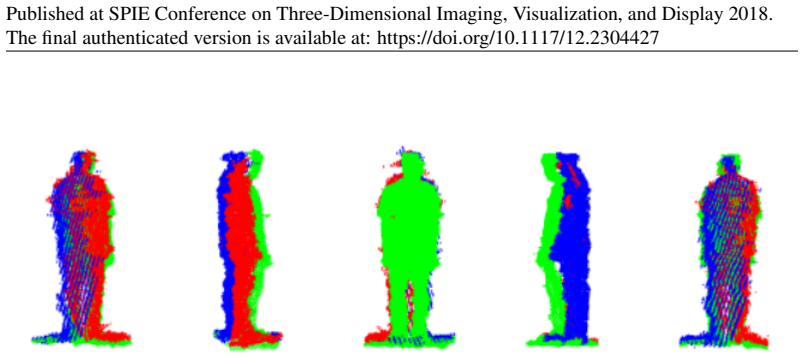
Summary. The paper proposes a 3D reconstruction system consisting of one structured-light (SL) depth camera and two or more mirrors. Each mirror is treated as a virtual depth camera, so the object is observed both directly and via virtual images, avoiding the synchronization and cost problems of multi-camera systems. The manuscript presents two reconstruction algorithms: Algorithm 1, which reprojects depth pixels and reflects those lying behind a mirror plane, and Algorithm 2, a voxel-carving variant that also checks virtual reflections. Mirror planes are calibrated from 3D marker positions using RANSAC and SVD. Experiments with a Kinect v1 reconstruct a sphere and a cylinder and report root-mean-square fitting errors below one centimeter, together with a qualitative human-body point cloud. The central accuracy claim, stated in Sec. 5.2, is that 'both measured errors were less than 1 centimeter.'
Significance. If the proposed method works as claimed, it is an attractive low-cost alternative to synchronized multi-camera rigs: a single matching-based depth camera with passive mirrors requires no synchronization and can in principle handle moving objects. The paper is clearly written and the algorithms are simple enough to reproduce. The experiments on simple geometric primitives are a reasonable first check, and the authors are honest about the qualitative nature of the human-body demonstration. However, the significance is bounded by two gaps: the load-bearing assumption about structured-light depth in mirror regions is only indirectly validated, and the main error metric measures how well the point cloud matches a fitted primitive rather than how accurately it matches the physical object. A direct test of the mirror-depth assumption and an absolute ground-truth comparison are needed before the sub-centimeter claim is fully established.
major comments (2)
- [Sec. 5.2, Eq. (4); Sec. 5.3, Eq. (5)] The quantitative accuracy claim is based on the RMSE of reconstructed points relative to a sphere or cylinder fitted to the same point cloud. This metric measures how sphere-like or cylinder-like the cloud is, not how accurately its absolute position, orientation, or scale matches the real object. A point cloud that is correctly shaped but globally translated or slightly rotated would receive the same reported error. The comparisons of the fitted sphere radius (117 mm vs. the manually measured 115 mm) and cylinder radius are helpful, but no absolute comparison of fitted center or cylinder axis with ground truth is provided. Please report errors against independently known geometry, including object position and dimensions, and, ideally, over multiple independent captures with statistics such as mean and standard deviation.
- [Sec. 5] The experimental evaluation appears to be based on single captures for each configuration: sphere at different mirror angles and cylinder at different distances. Without repeated trials, systematic bias cannot be separated from sensor noise, and the conclusion that the errors are lowest near a 120-degree mirror angle rests on a small number of unlabeled data points. Please provide per-trial measurements, error bars, or at least repeated acquisitions for at least one configuration, so the reader can judge the stability of the reported sub-centimeter errors.
minor comments (5)
- [Algorithm 2 and Sec. 5] The threshold t0 used in Algorithm 2 is never given a numerical value or a selection rule in Sec. 5, so the space-carving results cannot be reproduced from the manuscript alone.
- [Sec. 5.4] The statement that the non-optimized code processing one frame in about 0.2 seconds means the system 'could be expected' to run in real time is imprecise; 0.2 seconds per frame corresponds to 5 fps, which is better described as near-real-time or interactive rate.
- [Fig. 4 and Fig. 5] The captions of Figs. 4 and 5 do not define the labels used in the plots, such as 'raw', 'carved', or the axis units; making the plots self-contained would improve readability.
- [Sec. 5] The paper mentions that additional constraints such as background subtraction and color filtering were used, but their details and parameter values are not described, which limits reproducibility.
- [Sec. 1 and Related Work] The prior mirror-based RGB-D reconstruction work of Ref. [1] (Akay and Akgul) is cited but never compared quantitatively or qualitatively; a brief comparison would help position the novelty of the proposed system.
Circularity Check
The reconstruction derivation is not circular, but the headline sub-centimeter accuracy claim is a fit residual computed from the same fitted primitive it is used to validate.
-
fitted input called prediction
[Section 5.1, Section 5.2 Eq. (4), Section 5.3 Eq. (5)]
"Reconstruction accuracy was estimated by fitting each resulting point cloud according to its true shape and then calculating an error based on the cloud and fitted geometric parameters. ... Root mean square error (RMSE) was determined according to fitted center and radius in the case of a sphere ... Both measured errors were less than 1 centimeter."
Eq. (4) defines epsilon_sphere as the root-mean-square of [dist(P_i, c_hat) - R_hat], where c_hat and R_hat are the RANSAC-fitted sphere parameters obtained from the same point cloud {P_i}. Thus the reported 'less than 1 centimeter' error is by construction the residual of the cloud to its own best-fitting sphere, not an independent measurement of absolute reconstruction error against the real object. A point cloud that is merely approximately spherical, even with systematic positional or scale errors, will produce a small residual. The only independent check is the fitted radius (117 mm) versus the manually measured true radius (115 mm), which provides some grounding but does not validate the sub-centimeter residual claim. The same construction appears in Eq.
full rationale
The core reconstruction pipeline is not circular: mirror planes are estimated from 3D markers on the mirror surface via SVD and RANSAC, the reflection step uses the standard plane-reflection formula of Eq. (3), and Algorithm 1 simply reprojects depth pixels and reflects those classified as being behind mirrors. Section 2's two-reflection argument is an assumption about structured-light matching reliability inside mirror regions, not a derivation from the claimed output; it may be insufficiently validated, but that is a correctness/robustness concern, not a circularity concern. The paper does not rely on load-bearing self-citation: Ref. [2] is cited for depth-camera calibration context, but the actual calibration here is marker-based and described in the paper. The one genuine circularity-like step is the evaluation metric: Eqs. (4) and (5) measure error relative to geometric primitives fitted from the same point cloud being evaluated, so the central 'less than 1 centimeter' statement largely reports the fitting residual. The independent radius comparison (117 mm vs 115 mm) provides partial external grounding, which is why the circularity is only partial.
Assumptions & free parameters
free parameters (1)
- Threshold t0 in Algorithm 2
assumptions (4)
- domain assumption The structured-light pattern is flipped twice when traveling from the projector to the receiver via the real and virtual objects, so the matching algorithm sees an unchanged pattern and produces reliable depth for mirror reflections.
- domain assumption Depth values of pixels behind a mirror represent the distance to the virtual object surface, not to the mirror plane.
- domain assumption Each mirror is planar and can be represented by a four-parameter plane equation estimated from a few markers.
- standard math Reflection across a plane (Eq. 3) correctly maps virtual camera points to the real object surface.
Cite this review
Pith. "Pith review of Matching-based Depth Camera and Mirrors for 3D Reconstruction." pith.science (2026). https://pith.science/paper/EU5IOLGP
@misc{pith2026190806342,
  author       = {Pith},
  title        = {Pith review of: Matching-based Depth Camera and Mirrors for 3D Reconstruction},
  year         = {2026},
  howpublished = {\url{https://pith.science/paper/EU5IOLGP}},
  note         = {Machine review of arXiv:1908.06342}
}
read the original abstract
Reconstructing 3D object models is playing an important role in many applications in the field of computer vision. Instead of employing a collection of cameras and/or sensors as in many studies, this paper proposes a simple way to build a cheaper system for 3D reconstruction using only one depth camera and 2 or more mirrors. Each mirror is equivalently considered as a depth camera at another viewpoint. Since all scene data are provided by only one depth sensor, our approach can be applied to moving objects and does not require any synchronization protocol as with a set of cameras. Some experiments were performed on easy-to-evaluate objects to confirm the reconstruction accuracy of our proposed system.
Figures

Figures from the paper (3 more)

Reference graph
Works this paper leans on
-
[1]
A. Akay and Y . S. Akgul. 3d reconstruction with mirrors and rgb-d cameras. In Computer Vision Theory and Applications (VISAPP), 2014 International Conference on , volume 3, pp. 325–334, Jan 2014
work page 2014
-
[2]
E. Auvinet, J. Meunier, and F. Multon. Multiple depth cameras calibration and body vol- ume reconstruction for gait analysis. In Information Science, Signal Processing and their Applications (ISSPA), 2012 11th International Conference on , pp. 478–483, July 2012. doi: 10.1109/ISSPA.2012.6310598. 9 Published at SPIE Conference on Three-Dimensional Imaging,...
-
[3]
Learning OpenCV: Computer Vision with the OpenCV Library
Gary Bradski and Adrian Kaehler. Learning OpenCV: Computer Vision with the OpenCV Library. O’Reilly, Cambridge, MA, 2008
work page 2008
-
[4]
Harold Scott Macdonald Coxeter and Samuel L Greitzer. Geometry revisited, volume 19. Maa, 1967
work page 1967
-
[5]
T. Duckworth and D. J. Roberts. Camera image synchronisation in multiple camera real-time 3d reconstruction of moving humans. In Distributed Simulation and Real Time Applications (DS-RT), 2011 IEEE/ACM 15th International Symposium on , pp. 138–144, Sept 2011. doi: 10.1109/DS-RT.2011.15
-
[6]
Random sample consensus: a paradigm for model fitting with applications to image analysis and automated cartography
Martin A Fischler and Robert C Bolles. Random sample consensus: a paradigm for model fitting with applications to image analysis and automated cartography. Communications of the ACM, 24(6):381–395, 1981
1981
-
[7]
Multiple view geometry in computer vision
Richard Hartley and Andrew Zisserman. Multiple view geometry in computer vision . Cam- bridge university press, 2003
work page 2003
-
[8]
S. M. Khan, P. Yan, and M. Shah. A homographic framework for the fusion of multi-view silhouettes. In 2007 IEEE 11th International Conference on Computer Vision , pp. 1–8, Oct
work page 2007
Show all 15 references
-
[9]
A theory of shape by space carving
Kiriakos N Kutulakos and Steven M Seitz. A theory of shape by space carving. International Journal of Computer Vision, 38(3):199–218, 2000
2000
-
[10]
Accurate procedure for the calibration of a structured light system
Ricardo Legarda-Sa, Thorsten Bothe, Werner P Ju, et al. Accurate procedure for the calibration of a structured light system. Optical Engineering, 43(2):464–471, 2004
2004
-
[11]
Automated recon- struction of 3d scenes from sequences of images
Marc Pollefeys, Reinhard Koch, Maarten Vergauwen, and Luc Van Gool. Automated recon- struction of 3d scenes from sequences of images. ISPRS Journal of Photogrammetry and Remote Sensing, 55(4):251–267, 2000
2000
-
[12]
3D is here: Point Cloud Library (PCL)
Radu Bogdan Rusu and Steve Cousins. 3D is here: Point Cloud Library (PCL). In IEEE International Conference on Robotics and Automation (ICRA) , Shanghai, China, May 9-13 2011
2011
-
[13]
Computer vision: algorithms and applications
Richard Szeliski. Computer vision: algorithms and applications . Springer Science & Business Media, 2010
2010
-
[14]
Beginning Kinect Programming with the Microsoft Kinect SDK
Jarrett Webb and James Ashley. Beginning Kinect Programming with the Microsoft Kinect SDK. Apress, 2012. 10
2012
-
[2007]
doi: 10.1109/ICCV .2007.4408897
2007
Reviewed August 14, 2026 · model on record in the stance chip above.
Discussion (0). Continue with ORCID to comment.