REVIEW 4 major objections 6 minor 18 references
A New Technique of Camera Calibration: A Geometric Approach Based on Principal Lines
T0 review · 4 major / 6 minor · reviewed 2026-08-14 · deepseek-v4-flash
Pith's one-line read The paper proposes a closed-form geometric camera calibration that locates the principal point as the intersection of principal lines derived from individual homographies, and recovers per-image focal lengths, so calibration remains valid…
desk verdict The closed-form principal line idea is genuinely new and useful, but the focal-length derivation in Section 2.2.2 has a real hole: unnormalized line coefficients are treated as rotations, so the claimed formulas are not established. read the letter →
The pith
A machine-rendered reading of the paper's core claim, the machinery that carries it, and where it could break.
The reading
What carries the argument
The principal line: given a homography from a planar calibration pattern to the image, it is the line through the vanishing point of directions perpendicular to the pattern that is also perpendicular to the image of the intersection line of the two planes. The paper derives its coefficients in closed form from the homography entries, then uses the property that all principal lines meet at the principal point. This reduces calibration to intersecting straight lines, with each line carrying the relative orientation and position of the pattern up to one degree of freedom.
What would settle it
Capture many checkerboard poses with a lens known to have substantial radial distortion or with a sensor whose pixels are not square, compute each principal line from the paper's closed-form expression and the least-squares principal point, and compare the line-intersection residuals to those from a distortion-free simulation at the same noise level; if the residuals grow with distortion or skew beyond the noise prediction, the assumed principal-line property does not hold for such cameras.
Extended reading notes
Core claim
The central claim is that full camera calibration can be obtained analytically from the principal lines of a few planar-pattern images. For each pose, a closed-form rotation aligns the pattern so that one edge direction is parallel to the image of the plane intersection; the line through the resulting vanishing point, perpendicular to that edge direction, is the principal line. By a geometric property adopted from earlier work, every principal line passes through the principal point, so the principal point is recovered as the least-squares intersection of these lines. After shifting and rotating the image and world coordinate systems so their origins lie on the optical axis, and assuming circular symmetry of the imaging system, the homography takes a sparse form from which the focal length and relative pose of each image can be read off directly. The paper further claims that the same construction gives simple outlier screening: patterns whose recovered elevation or azimuth falls outside recommended ranges can be discarded, and per-image focal-length recovery makes the method valid when the focal length varies between pictures.
Load-bearing premise
The derivation assumes, from earlier work, that every principal line passes through the principal point; if that geometric property fails for a real camera, for example under skew or lens distortion, the estimated principal point and the focal lengths built on it are wrong.
Editorial extensions
If this is right
- Calibration can be performed with fewer captured frames: one homography per pose yields one principal line, and the principal point is the least-squares intersection of these lines, with no iterative initialization.
- Focal lengths can be recovered per image, so cameras with zoom lenses, autofocus, or other mixed-focal-length sequences can be calibrated from a single session.
- Ill-posed calibration planes can be detected automatically from the recovered elevation and azimuth parameters and discarded before the final estimate is computed.
- Because each principal line is closed-form, the per-image computation cost is low enough to screen many candidate poses and keep only the well-conditioned ones.
Reading between the lines
- Beyond the paper, the per-image focal-length recovery suggests online or self-calibration of zoom and autofocus cameras, a use case the paper mentions but does not develop into a continuous runtime procedure.
- Beyond the paper, the closed-form principal-line coefficients could serve as a differentiable layer in learning-based calibration pipelines, since they map homography entries to geometric parameters without nonlinear optimization.
- Beyond the paper, the same line-intersection step could be used to reject transient checkerboard detections in simultaneous localization and mapping systems, where only a few frames of a planar pattern are available at a time.
Signed reviews
Editorial analysis
A structured set of objections, weighed in public.
Referee Report
Summary. The manuscript proposes a camera calibration method based on 'principal lines' computed in closed form from a single homography per calibration plane. The principal point is obtained as the least-squares intersection of principal lines from multiple poses, and the focal length is derived per image by transforming the image-plane and world coordinate systems so that the calibration-plane homography takes a sparse form. The method is claimed to be simpler, more robust to bad poses, and able to handle varying focal length, in contrast to Zhang's method. The paper includes synthetic and real experiments comparing the proposed approach with Zhang's method.
Significance. If the correctness issues are resolved, the paper would provide a genuinely analytic calibration pipeline with two practical advantages: per-image focal length recovery and principled outlier/pose screening. The closed-form principal-line construction is a useful addition to the calibration toolbox, and the experiments (modulo baseline details) suggest practical viability. However, the focal-length derivation as printed contains a serious gap that affects the central claim, so the current version's significance cannot be fully assessed.
major comments (4)
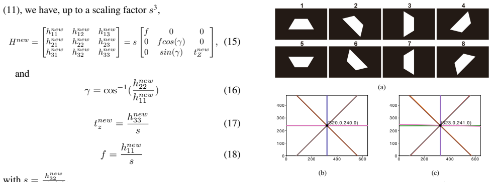
- [Section 2.2.2, Eq. (12)] The matrices H1r and H2r in Eq. (12) are constructed from the coefficients (a',b') and (a,b) of the principal line and its WCS counterpart, but these coefficients are defined only up to scale in Eq. (8) and the paper never normalizes them; as a result, H1r and H2r are not necessarily rotations, and the conjugation in (12) is not a similarity of the image/WCS planes, so the claimed form of Hnew in Eq. (15) does not follow. For instance, with H = [[1,0,0],[0,cosγ,-d sinγ],[0,sinγ,d cosγ]], the principal line has a'=-sinγ, b'=0, and substituting the unnormalized matrices into (12) yields an Hnew with a nonzero (2,3) entry and a sign discrepancy in (3,2), contrary to (15). Since Eqs. (18) and (19) derive the focal length and extrinsics from (15), the full-calibration claim rests on this gap. The authors should either explicitly normalize the line coefficients to unit length (and define the corresponding normalization of the WCS line, which must be consistent with the transformation [a,b,c]^T = H^T [a',b',c']^T) or re-derive the structure of Hnew with general scale factors.
- [Section 2.1.2] The principal line equation is not completely derived: the constant c' is deferred to the supplementary material ('The algebraic solution of c is listed in the supplementary material'), yet the principal-point estimate in Eq. (9) depends on c'_i for every image. The closed-form solution claimed in the abstract and Section 1 is therefore incomplete as presented. Please include the expression for c' in the main text or in an appendix within the paper.
- [Section 2.2.2, around Eq. (13)] The claim that the transformed IPCS/WCS pair satisfies Rnew = Rx(γ) (α=β=0) and Tnew = (0,0,tnew_z) is justified only by 'it is easy to see.' This relative orientation/translation is the geometric basis for the sparse matrix in Eq. (15), so the claim is load-bearing. A derivation (or a precise constructive definition of the two coordinate systems) is needed to show that after shifting the origins to the principal point and its pre-image and rotating about the principal-line direction, the remaining relative rotation is a single rotation about the X axis and the translation is purely along Z.
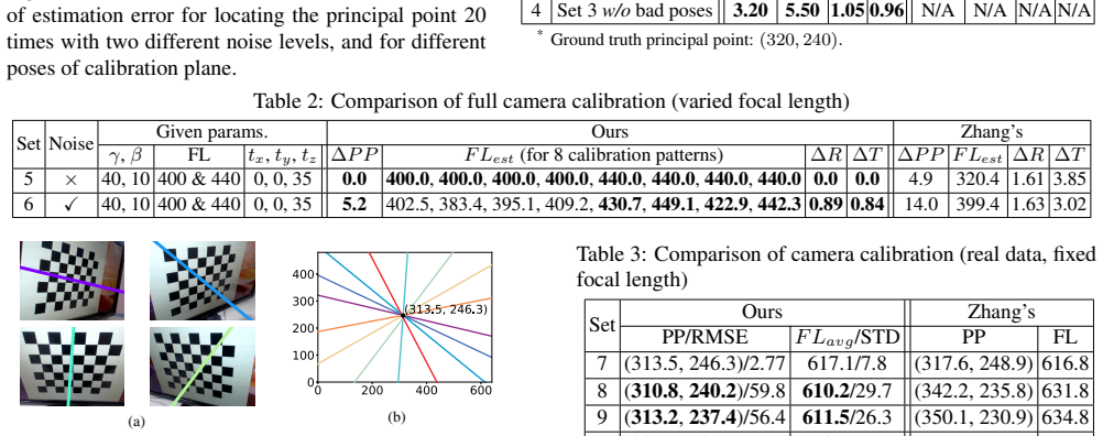
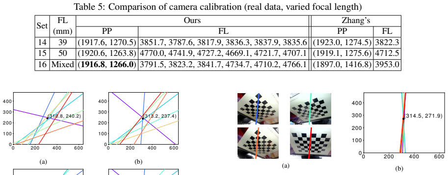
- [Section 3, Tables 1-3] The experiments compare against 'Zhang's method' but do not specify the baseline implementation, in particular whether the nonlinear maximum-likelihood refinement stage of Zhang's method is included. In the standard Zhang pipeline, the closed-form solution is followed by nonlinear refinement, which typically yields errors well below 10 pixels in the principal point for 1-pixel noise. Without this detail, the reported advantage (e.g., Set 1: ∆PP 4.4 vs 15.0 pixels) is not interpretable and the stated conclusion that the proposed approach 'compares favorably with Zhang's method' is not fully supported. Please describe the baseline algorithm precisely and, if refinement was omitted, include it for a fair comparison.
minor comments (6)
- [Section 2.2.2] The point p0=(u0,v0,1)^T in WCS that corresponds to the principal point is not defined explicitly; state that p0 = H^{-1} p'_0, and note that H^{-1} exists for a non-degenerate calibration plane.
- [Section 2.1.1] The replacement of k1 by 1/2 in Eq. (7) is a change of the scale of the vector A'B' and should be described as 'up to a scale factor' to avoid the impression that k1 is an independent free parameter.
- [Throughout] The name 'Zhangs method' should be 'Zhang's method' (e.g., in the abstract, introduction, and table captions).
- [Figure 3(b)] The caption 'Eight (but merged into four) principal lines' is confusing; rephrase to 'eight principal lines, which appear as four due to symmetry.'
- [Table 1] The caption does not define ∆R and ∆T; refer to Eqs. (20)-(23).
- [Section 3.2.1] The threshold of 15 used for RMSE-based outlier removal in Sets 11-13 is introduced without justification; briefly explain how this threshold was chosen.
Circularity Check
No significant circularity; derivation is self-contained up to an external geometric premise, with at most a redundant self-citation.
full rationale
The claimed derivation is not circular. Section 2.1 obtains each principal line in closed form from a single homography H (Eqs. 2-8), using only the parallelism condition and a vanishing point; no target camera parameter is used as an input. The principal point is then the least-squares intersection of these lines (Eq. 9), and the only external input is the geometric property, taken from [1] and [7], that the principal line passes through the principal point. Although [7] is a prior paper by one of the present authors, [1] is an independent source for that property, and the property is a verifiable geometric statement rather than a definition of the paper's output. The focal-length derivation (Eqs. 12-18) similarly constructs a transformed homography from known quantities—H, line coefficients, and the estimated principal point—and reads f from an entry of Hnew; it does not fit f to the data it later reports. The skeptical issue about unnormalized coefficients (a', b') in H1r and H2r is a rigor gap: if the coefficients are not unit vectors, the matrices are not rotations and the special form (15) is not established. That is a correctness concern, not circularity, because the output would not reduce to an input by construction. No load-bearing step is equivalent to its own inputs, so no circular step is exhibited; the redundant self-citation [7] is not load-bearing because the same premise is independently supported by [1].
Assumptions & free parameters
free parameters (1)
- outlier removal RMSE threshold =
15
assumptions (4)
- domain assumption Principal line passes through the principal point
- domain assumption Special geometry R1 and R2: image of iX is parallel to ix, and image of iY is perpendicular to ix
- domain assumption Camera has circular symmetry (zero skew, square pixels)
- domain assumption Homography H is known accurately from point correspondences
Cite this review
Pith. "Pith review of A New Technique of Camera Calibration: A Geometric Approach Based on Principal Lines." pith.science (2026). https://pith.science/paper/AZTNGWFG
@misc{pith2026190806539,
  author       = {Pith},
  title        = {Pith review of: A New Technique of Camera Calibration: A Geometric Approach Based on Principal Lines},
  year         = {2026},
  howpublished = {\url{https://pith.science/paper/AZTNGWFG}},
  note         = {Machine review of arXiv:1908.06539}
}
read the original abstract
Camera calibration is a crucial prerequisite in many applications of computer vision. In this paper, a new, geometry-based camera calibration technique is proposed, which resolves two main issues associated with the widely used Zhang's method: (i) the lack of guidelines to avoid outliers in the computation and (ii) the assumption of fixed camera focal length. The proposed approach is based on the closed-form solution of principal lines (PLs), with their intersection being the principal point while each PL can concisely represent relative orientation/position (up to one degree of freedom for both) between a special pair of coordinate systems of image plane and calibration pattern. With such analytically tractable image features, computations associated with the calibration are greatly simplified, while the guidelines in (i) can be established intuitively. Experimental results for synthetic and real data show that the proposed approach does compare favorably with Zhang's method, in terms of correctness, robustness, and flexibility, and addresses issues (i) and (ii) satisfactorily.
Figures


Figures from the paper (3 more)

Reference graph
Works this paper leans on
-
[1]
A. S. Alturki and J. S. Loomis. Camera principal point estimation from vanishing points. In 2016 IEEE National Aerospace and Electronics Conference (NAECON) and Ohio Innovation Summit (OIS), pages 307–313, July 2016
work page 2016
- [2]
-
[3]
B. Caprile and V . Torre. Using vanishing points for cam- era calibration. International Journal of Computer Vision , 4(2):127–139, Mar 1990
work page 1990
- [4]
- [5]
-
[6]
H. Hirschmuller. Accurate and efficient stereo processing by semi-global matching and mutual information. In 2005 IEEE Computer Society Conference on Computer Vision and Pattern Recognition (CVPR’05), volume 2, pages 807–814 vol. 2, June 2005
work page 2005
-
[7]
M.-T. Lu and J.-H. Chuang. Fully automatic camera cali- bration for principal point using flat monitors. pages 3154– 3158, 10 2018
work page 2018
-
[8]
S. J. Maybank and O. D. Faugeras. A theory of self- calibration of a moving camera. International Journal of Computer Vision, 8(2):123–151, Aug 1992
work page 1992
Show all 18 references
-
[9]
Mohedano and N
R. Mohedano and N. Garcła. Capabilities and limitations of mono-camera pedestrian-based autocalibration. In 2010 IEEE International Conference on Image Processing, pages 4705–4708, Sep. 2010
2010
-
[10]
Ricolfe-Viala and A
C. Ricolfe-Viala and A. Sanchez-Salmeron. Optimal condi- tions for camera calibration using a planar template. In 2011 18th IEEE International Conference on Image Processing , pages 853–856, Sep. 2011
2011
-
[11]
Rojtberg and A
P. Rojtberg and A. Kuijper. [poster] efficient pose selection for interactive camera calibration. In 2017 IEEE Interna- tional Symposium on Mixed and Augmented Reality (ISMAR- Adjunct), pages 182–183, Oct 2017
2017
-
[12]
Sangi and M
M. Sangi and M. Jahed. A fast 3d hand model reconstruction by stereo vision system. In 2010 The 2nd International Con- ference on Computer and Automation Engineering (ICCAE), volume 5, pages 545–549, Feb 2010
2010
-
[13]
L. Tan, Y . Wang, H. Yu, and J. Zhu. Automatic camera cali- bration using active displays of a virtual pattern. In Sensors, 2017
2017
-
[14]
Z. Tang, Y . Lin, K. Lee, J. Hwang, J. Chuang, and Z. Fang. Camera self-calibration from tracking of moving persons. In 2016 23rd International Conference on Pattern Recognition (ICPR), pages 265–270, Dec 2016
2016
-
[15]
R. Tsai. A versatile camera calibration technique for high- accuracy 3d machine vision metrology using off-the-shelf tv cameras and lenses. IEEE Journal on Robotics and Automa- tion, 3(4):323–344, August 1987
1987
-
[16]
Wang and W.-H
L.-L. Wang and W.-H. Tsai. Camera calibration by vanishing lines for 3-d computer vision. IEEE Trans. Pattern Anal. Mach. Intell., 13(4):370–376, Apr. 1991
1991
-
[17]
P. Woit. Quantum theory, groups and representations: An introduction. Columbia University. March, 13, 2016
2016
-
[18]
Z. Zhang. A flexible new technique for camera calibration. IEEE Transactions on Pattern Analysis and Machine Intelli- gence, 22(11):1330–1334, Nov 2000
2000
Reviewed August 14, 2026 · model on record in the stance chip above.
Discussion (0). Continue with ORCID to comment.