REVIEW 6 minor 11 references
The SPICEcore Hole Camera System
T0 review · 0 major / 6 minor · reviewed 2026-08-14 · deepseek-v4-flash
Pith's one-line read A borehole camera estimates the scattering length of Antarctic ice from the angular width of back-scattered LED light.
desk verdict Honest instrument paper: new hardware and a first 1.7 km deployment data set, with the authors openly labeling the physics extraction as work in progress; the main foregrounds (harness shadow, ESTISOL-140) are named but not yet modeled. read the letter →
The pith
A machine-rendered reading of the paper's core claim, the machinery that carries it, and where it could break.
The reading
What carries the argument
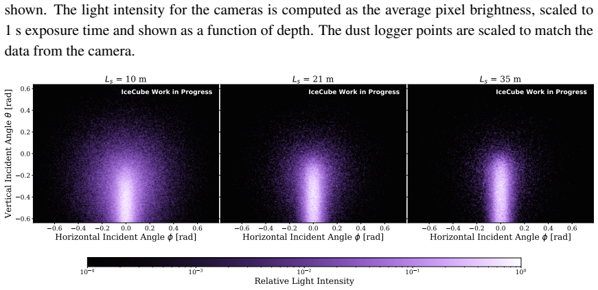
The load-bearing object is a set of three pairs of cameras and LEDs mounted inside a glass pressure vessel. The cameras use IMX219 CMOS image sensors with fish-eye lenses, spaced 120 degrees apart, and each is aligned with a 470 nm LED that emits a beam 7 degrees wide at half maximum with 170 mW output; the three pairs interleave exposures to raise the data rate. The measurement principle is shape-based: instead of absolute intensities, the images record the spread of the back-scattered light in horizontal and vertical incidence angles, and the metric $2.0\,\sigma_\phi+\sigma_\theta$ — twice the RMS width in horizontal angle plus the RMS width in vertical angle — is calibrated against scattering length in Monte Carlo simulations. A brush ring and tight flange structure suppress reflections from the hole surface and the glass, and a 3-axis magnetometer plus time-stamped depth logs give each image its orientation and depth.
What would settle it
Lower the same camera into a laboratory tank or ice block with a known, independently measured scattering length and compare the measured $2.0\,\sigma_\phi+\sigma_\theta$ against the simulated curve; a significant mismatch, or a change in the image when only the harness or vessel orientation is moved, would show that internal reflection or hardware geometry, not bulk ice scattering, controls the images.
Extended reading notes
Core claim
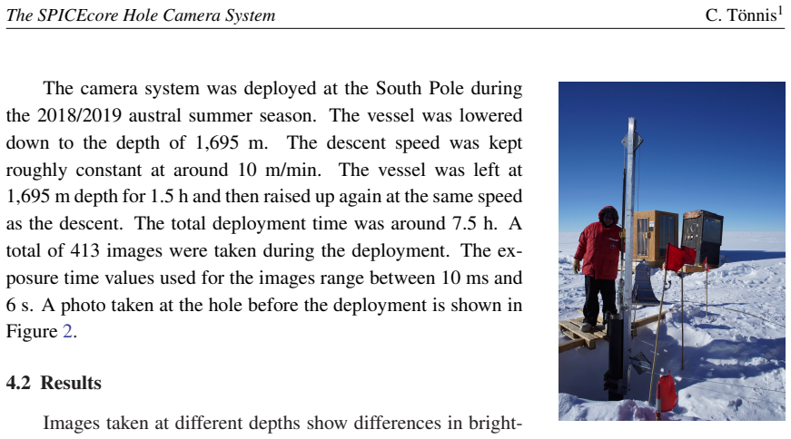
The central claim is that a compact borehole camera can serve as an ice-property probe: by imaging the light scattered back from a narrow, bright 470 nm LED beam, the angular width of the illuminated region maps to the effective scattering length of the surrounding ice. In the first SPICEcore deployment the device reached 1,695 m and took 413 images, and the depth dependence of the average back-scattered light intensity correlates with the independently measured laser dust-logger profile, with the transition from bubbly to clear ice visible around 1,000 m. Simulated images generated with photon-propagation software for effective scattering lengths of 10, 21, and 35 m reproduce the shrinking illuminated area seen in the data, and the paper defines a width parameter $2.0\,\sigma_\phi+\sigma_\theta$ that tracks the true scattering length in simulation. The paper presents this as validation of the camera concept and as groundwork for estimating scattering lengths after residual systematics, such as the harness shadow and the ESTISOL-140 borehole fluid, are modeled.
Load-bearing premise
The load-bearing premise is that the light seen by the cameras is dominated by photons scattered in the bulk ice, not by reflections off the borehole fluid, the glass pressure vessel, or the harness; if reflections dominate, the measured spot width tells you about hardware geometry, not ice scattering.
Editorial extensions
If this is right
- If the shape-based measurement is valid, the scattering length of ice can be estimated without radiometric calibration of the camera or the LED.
- The same hardware concept can serve as the calibration camera for IceCube Upgrade optical modules, as the paper explicitly proposes.
- Repeated deployments along the hole can map where ice clarity changes, complementing the dust logger and the existing flasher-based ice model.
- Because the system records orientation, future improved versions can search for direction-dependent light propagation in the ice, an anisotropy the IceCube collaboration has reported.
- The demonstrated combination of an intense narrow beam, short exposures, and autonomous operation defines the operating envelope for future down-hole camera probes.
Reading between the lines
- A natural extension would be to co-deploy the camera with a calibrated reference scatterer in the borehole fluid, which would isolate the fluid's contribution from the ice signal before the full systematic model is built.
- The same width-parameter analysis could be applied to the existing LED flasher data inside IceCube, giving a camera-style cross-check of the current ice model without new hardware.
- If the correlation with the dust logger holds at finer depth sampling, the camera could become a high-resolution dust-layer mapper; the reported analysis aggregates intensity over the full image and does not yet test that resolution.
- Seasonal redeployment in the same hole could track how ice clarity or the ESTISOL-140 column evolves, a measurement the paper leaves implicit.
Signed reviews
Editorial analysis
A structured set of objections, weighed in public.
Referee Report
Summary. This paper describes the design, construction, and first field deployment of the SPICEcore hole camera system, a pressure-vessel instrument with three CMOS cameras and three 470 nm LEDs intended to measure optical scattering in Antarctic ice. The prototype was lowered to 1,695 m in the SPICEcore hole, acquired 413 images, and the paper reports depth-dependent image brightness and angular width, compares the brightness profile to a scaled laser dust-logger profile, and shows Monte Carlo simulations relating a width parameter (2.0 σφ + σθ) to effective scattering length. The stated conclusion is that the deployment is a proof of concept for the camera concept and for IceCube Upgrade camera calibration.
Significance. If judged as an instrument-and-first-deployment report, this is a useful and credible contribution. The hardware description is specific, the deployment data are real (413 images over a 0-1,695 m depth range), and the simulations use a measured LED emission profile. The explicit acknowledgment that absolute calibration, harness shadow, and ESTISOL-140 effects must be studied before reliable scattering-length results are appropriate. The key limitation is that the paper does not yet demonstrate that the measured angular width is a valid estimator of ice scattering length; however, the text labels this analysis as work in progress, so that limitation does not undermine the instrument proof-of-concept claim.
minor comments (6)
- [§4.2, Fig. 4] The phrase 'independently measured with the laser-based dust logger' followed by 'the data were scaled to each other' is potentially misleading. Because the dust-logger points are scaled to match the camera brightness, the agreement in Fig. 4 is an illustration of common depth trends, not an independent validation. Please reword the caption and text to say this explicitly.
- [§4.2, Eqs. (4.1)-(4.2)] The width parameters σφ and σθ are defined for simulated photons, but the paper does not state how the same estimator is evaluated on a captured image (e.g., as an intensity-weighted RMS over pixels). Please add the data-side definition and ensure it is exactly the estimator used for the comparison with simulations.
- [§4.2, Figs. 3 and 5] The harness shadow is visible as a sharp cut in Fig. 3 and is later listed as a systematic effect that 'have to be studied', but no mask or correction is applied to the width parameters. Please state at the point where σφ and σθ are introduced that the application to data is preliminary and uncorrected for the shadow.
- [§4.2, Fig. 4] The brightness profile is obtained by averaging pixel brightness and scaling to 1 s exposure time, yet the exposure times span 10 ms to 6 s. The paper should state how frames with different exposures, cameras, and orientations were selected and whether pixel saturation or sensor nonlinearity was checked.
- [Fig. 6 caption] The caption refers to 'true geometric scattering lengths' while the axis label says 'true effective scattering length'; please reconcile these terms or define the relationship.
- [§2.2 and Eq. (4.1)] The sentence after Eq. (4.1) saying 'the average horizontal and vertical arrival angle' appears to contain a typo; it should say 'the average vertical arrival angle' for σθ. There is also a minor notation inconsistency between σθ and the subsequent text.
Circularity Check
No significant circularity: the paper reports a first instrument deployment and explicitly labels the scattering-length analysis as still under development.
full rationale
This is a hardware and first-deployment paper, not a derivation paper, so the standard circularity failure modes do not arise. The central claim is that a camera system was designed, deployed, and produced images whose depth-dependent brightness resembles the known dust-logger profile; the paper does not claim a completed scattering-length measurement. The Figure 4 comparison is explicitly described as illustrative: 'The data were scaled to each other in order to illustrate the correlation between these measurements' and 'The dust logger points are scaled to match the data from the camera.' Scaling both curves for visualization is not a fitted prediction, and the depth-dependent shape of the transition at around 1,000 m is not manufactured by a single normalization. The width parameters sigma_phi and sigma_theta are defined independently from the images, and the combination 2.0*sigma_phi + sigma_theta is chosen in Monte Carlo because it correlates with scattering length; the paper then states that an analysis method is 'being developed' and explicitly lists the harness shadow and ESTISOL-140 effects as systematics that 'have to be studied' before reliable results are possible. No load-bearing argument is reduced to a self-citation: references to IceCube ice models and photon-propagation software are standard supporting tools, not uniqueness theorems or fitted inputs. The proof-of-concept conclusion is honestly limited to demonstrating that the device operates and produces plausible images, rather than claiming a validated ice-property measurement.
Assumptions & free parameters
free parameters (2)
- dust logger scaling factor =
not quoted (matches camera intensity profile)
- weight 2.0 in 2.0σφ + σθ =
2.0
assumptions (4)
- domain assumption The back-scattered light recorded by the cameras originates from scattering in the bulk ice, with negligible contribution from reflections at the hole surface, glass, or internal structures.
- domain assumption Camera pixel brightness is proportional to exposure time and to incident light intensity over the 10 ms to 6 s range used.
- domain assumption Pixel angles θ and φ are correctly mapped from the camera field of view using refractive indices of air, glass, and ice.
- domain assumption Monte Carlo photon propagation software [10] accurately models LED emission, ice scattering, and camera optics for the simulated images.
Cite this review
Pith. "Pith review of The SPICEcore Hole Camera System." pith.science (2026). https://pith.science/paper/ZZWYTH64
@misc{pith2026190807733,
  author       = {Pith},
  title        = {Pith review of: The SPICEcore Hole Camera System},
  year         = {2026},
  howpublished = {\url{https://pith.science/paper/ZZWYTH64}},
  note         = {Machine review of arXiv:1908.07733}
}
read the original abstract
IceCube is a cubic-kilometer scale neutrino telescope located at the geographic South Pole. The detector utilizes the extremely transparent Antarctic ice as a medium for detecting Cherenkov radiation from neutrino interactions. As a result of extensive studies of the optical properties of ice, the light propagation in IceCube is well understood. The ice properties are, however, still dominant sources of detector systematic uncertainties in many IceCube analyses. We have designed a camera system to measure the optical properties of the Antarctic ice surrounding the SPICEcore hole that is an ice-core hole drilled down to 1.7~km near the IceCube detector. The device uses CMOS image sensors to measure the back-scattered light from bright LEDs pointing into the ice. Having a similar measurement principle, the device can also serve as a proof of concept of a camera system designed for the optical modules for IceCube Upgrade. During the 2018/2019 austral summer season, a prototype of the instrument was deployed in the ice-core hole. In this contribution, we present the hardware design of the camera system and the result of the first deployment at the South Pole.
Figures


Figures from the paper (3 more)


Reference graph
Works this paper leans on
-
[1]
IceCube Collaboration, M. G. Aartsen et al., JINST 12 (2017) P03012. 7 The SPICEcore Hole Camera System C. Tönnis1 101 True Effective Scattering Length [m] 0.5 0.6 0.7 0.8 0.9 2.0 + IceCube Work in Progress Figure 6: The spread of the parameter 2 .0σφ + σθ is shown for the nine Monte Carlo data sets corresponding to different true geometric scattering len...
work page 2017
-
[2]
IceCube Collaboration, M. G. Aartsen et al., Science 342 (2013) 1242856
2013
-
[3]
IceCube Collaboration, M. G. Aartsen et al., Science 361 (2018) 147-151
work page 2018
-
[4]
IceCube Collaboration, M. G. Aartsen et al., Nucl Instrum. & Meth. A711 (2013) 73
work page 2013
-
[5]
IceCube Collaboration, PoS(ICRC2019)928 (these proceedings)
-
[6]
K. A. Casey et al., Annals of Glaciology 55 (2014) 137-146
work page 2014
-
[7]
IceCube Collaboration, PoS(ICRC2019)847 (these proceedings)
-
[8]
IceCube Collaboration, PoS(ICRC2019)983 (these proceedings)
Show all 11 references
-
[9]
N. E. Bramall et al., Geophys. Res. Lett. 32 (2005) L21815
2005
-
[10]
IceCube Collaboration, M. G. Aartsen et al., Nucl Instrum. & Meth . A725 (2013) 141-143
2013
-
[11]
Chirkin in ICRC2013, p.580, 2013
IceCube Collaboration, D. Chirkin in ICRC2013, p.580, 2013. 8
2013
Reviewed August 14, 2026 · model on record in the stance chip above.
Discussion (0). Continue with ORCID to comment.