REVIEW 2 major objections 3 minor 13 references
Steady state cyclic behaviour of a half-plane contact in partial slip subject to varying normal load, moment, shear load, and moderate differential bulk tension
T0 review · 2 major / 3 minor · reviewed 2026-08-14 · deepseek-v4-flash
Pith's one-line read A half-plane contact's permanent stick zone is obtained from its normal-load solution through a simple mapping.
desk verdict Genuine extension to moment-loaded half-plane contact with a useful mapping, but the bulk-tension branch has a sign error that flips the predicted stick-zone shift; correctable, but not as printed. read the letter →
The pith
A machine-rendered reading of the paper's core claim, the machinery that carries it, and where it could break.
The reading
What carries the argument
The load-bearing object is the mapping between the normal contact problem and the tangential steady-state problem, displayed as equation (25). It is derived by comparing the locked-in surface strain over the permanent stick zone at the two load-reversal points; the inversion of the resulting integral equation is identical in form to the normal-contact inversion, which is exactly why the mapping works. Under the assumption that the bulk tension never reverses slip at a contact edge, this machinery converts a tangential problem into a normal problem with adjusted load and tilt, requiring no further algebra.
What would settle it
Compute the steady-state slip-stick boundary for a tilted wedge contact with $\Delta\sigma$ large enough that one contact edge reverses its slip direction; if the observed permanent stick zone still matches the mapped normal solution (31)-(32), the moderate-$\Delta\sigma$ restriction is unnecessary. More directly, a direct numerical simulation or experiment measuring $[-m,n]$ for a known $P_0$, $\Delta Q$, $\Delta\sigma$, and $\alpha_0$ would settle whether the mapping is correct.
Extended reading notes
Core claim
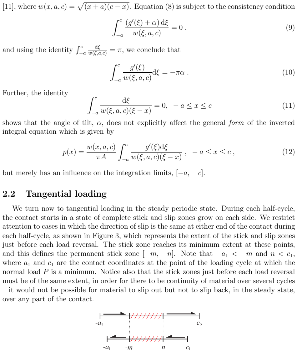
The central discovery is a formal correspondence between the normal contact problem and the steady-state tangential problem. When the oscillatory loads are synchronous, the corrective shear traction $q^*_2-q^*_1$ over the permanent stick zone is a scaled copy of the pressure distribution of a normal contact whose load and tilt are adjusted. Explicitly, the mapping sends $[-a,c]$ to $[-m,n]$, $p(x)$ to $-\frac{1}{2f}[q^*_2-q^*_1](x)$, $P$ to $P_0-\Delta Q/(2f)$, and $\alpha$ to $\alpha_0-A\Delta\sigma/(8f)$. Once this mapping is accepted, the permanent stick-zone boundaries $[-m,n]$ are found by solving the normal contact problem at the adjusted load and tilt, and the maximum slip extents follow by subtracting these boundaries from the contact coordinates at the two load extremes.
Load-bearing premise
The entire construction assumes the oscillatory bulk tension is moderate enough that, during each half-cycle, slip at both contact edges runs in the same direction and no edge reverses its slip sense; if that fails, the permanent stick zone as defined here no longer exists.
Editorial extensions
If this is right
- The permanent stick zone depends on $P_0$, $\Delta Q$, $\Delta\sigma$, and $\alpha_0$ only; the mean shear $Q_0$ and mean bulk tension $\sigma_0$ drop out of the steady-state result.
- For any incomplete half-plane contact with equal elastic constants, the permanent stick zone is obtained from the normal solution with no extra algebra.
- The maximum slip extents, $(a_i-m)$ and $(c_i-n)$, follow by computing the contact coordinates at the two load extremes, which requires $\Delta P$ and $\Delta M$ as additional inputs.
- The shear traction distribution in the permanent stick zone is a scaled copy of the mapped normal pressure, so quantities such as slip displacement can be evaluated after the mapping.
- Application to a flat-and-rounded contact is straightforward although algebraically heavier than the wedge example.
Reading between the lines
- A practical consequence the authors do not spell out: any existing normal-contact solver, analytical or numerical, can be reused as a fretting predictor by feeding it the adjusted load and tilt, with the only extra bookkeeping being the threshold at which the moderate-$\Delta\sigma$ assumption fails.
- A testable extension would be to derive the explicit reversed-slip boundary, where $m=a$ or $n=c$, as a function of $P_0$, $\Delta Q$, $\Delta\sigma$, and $\alpha_0$; the paper stops at noting that the solution limit is reached there.
- The mapping exploits synchronous oscillations; an extension to phase-shifted loads would have to revisit the locked-in strain equality that anchors the permanent stick zone.
Signed reviews
Editorial analysis
A structured set of objections, weighed in public.
Referee Report
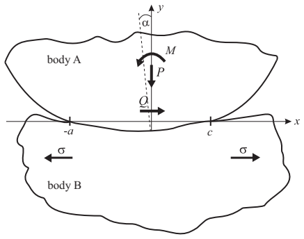
Summary. The paper presents an analytical solution for the steady-state partial-slip response of a two-dimensional half-plane contact under synchronously oscillating normal load P, shear force Q, moment M, and differential bulk tension σ. The authors write the tangential problem in terms of sliding shear tractions plus a corrective traction over the permanent stick zone, and by equating surface strains at the two load extremes they derive an integral equation for the corrective traction difference. This equation is mapped onto the corresponding normal contact problem, yielding a recipe in which the permanent stick zone [−m, n] is obtained from the normal solution with modified load and tilt parameters (Eq. (25)). The mapping is applied to a tilted wedge, giving closed-form expressions for the stick-zone boundaries (Eqs. (31)-(32)) and for the corrective shear traction (Eq. (33)). The paper emphasizes the restriction to 'moderate' bulk tension, meaning that the slip direction is never reversed at a contact edge.
Significance. If correct, the proposed mapping would be a valuable extension of the Ciavarella-J"ager and Barber-Davies-Hills ideas, converting a nontrivial steady-state partial-slip problem with normal, shear, moment, and bulk-tension variation into a known normal contact calculation. The derivation is systematic, uses no fitted parameters, and the wedge example provides closed-form, independently checkable predictions. The paper is also clearly written and the intended application to fretting problems is plausible. However, the significance is conditional: the bulk-tension branch of the central mapping is internally inconsistent, as detailed below, so the claimed recipe cannot be accepted as printed.
major comments (2)
- [Section 2.2, Eq. (16)-(17)] The derivation of Eq. (17) from Eq. (16) contains a sign error. Substituting the normal-contact identity (5) into each of the two sliding-traction integrals in Eq. (16) gives 2f(dg/dx+α0) for those two terms. The remaining bulk term is −A(σ2−σ1)/4, which, with the paper's definition Δσ=σ1−σ2, equals +AΔσ/4. After dividing by A, the constant term on the left of Eq. (17) must therefore be +Δσ/4, not −Δσ/4. This is not a convention-dependent sign: the error propagates into Eq. (23), Eq. (25), and Eq. (32). With the corrected sign, Eq. (23) should read ∫g'/w = −πα0 − AπΔσ/(8f), the mapping in Eq. (25) should read α → α0 + AΔσ/(8f), and Eq. (32) should contain +πAΔσ/(16fφ) in the argument of the sine.
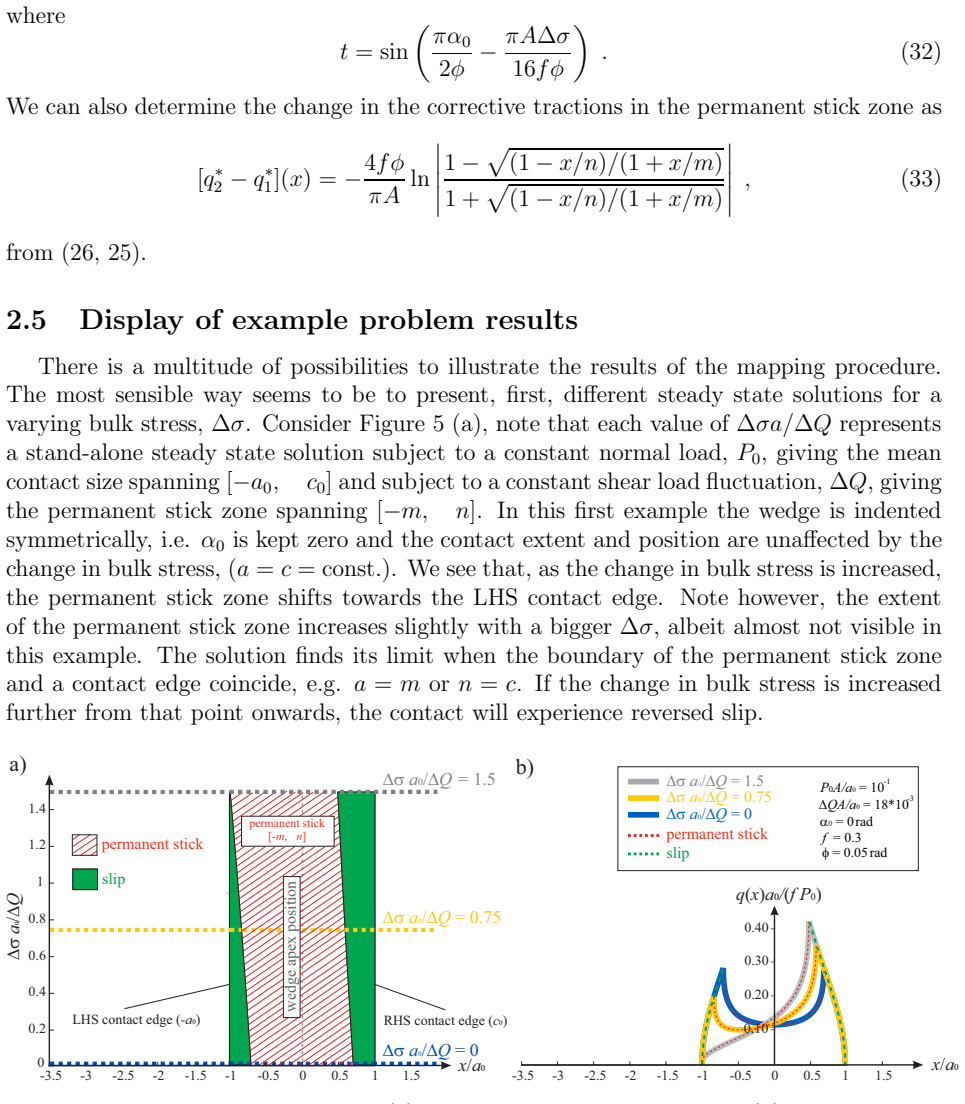
- [Section 2.5, Figure 5 and Eq. (32)] The printed sign in Eq. (32) reverses the predicted direction of the permanent-stick-zone shift, contradicting the paper's own text and figure. For α0=0 and Δσ>0, Eq. (32) as printed gives t<0, so m<K and n>K, i.e. the stick zone moves toward the right-hand contact edge. Section 2.5 states, and Figure 5 depicts, that increasing Δσ shifts the permanent stick zone toward the left-hand edge. The internally consistent derivation gives t>0 and the leftward shift, so the displayed example results and the formula set disagree. Since this sign appears in the central mapping claim, the bulk-tension branch of the solution is not reliable as printed.
minor comments (3)
- [Section 2, opening] The 'moderate' bulk-tension restriction is only described verbally as insufficient to reverse the slip direction at either edge; the paper would benefit from a quantitative criterion in terms of P0, ΔQ, Δσ, and geometry, so that the domain of validity of Eqs. (31)-(33) is explicit.
- [Figures 5-6] Several axis labels and subscripts in the arXiv figures are poorly rendered, for example the fractions Δσa/ΔQ and the α0/φ labels, which makes independent checking of the plotted results unnecessarily difficult.
- [Eq. (13)-(14)] The signs of the σ1 and σ2 terms are consistent with the rest of the paper, but the convention is easy to lose; a sentence explicitly fixing the positive directions of σ1, σ2 and Δσ in Figure 1 would help.
Circularity Check
No significant circularity: the mapping from the normal to the tangential problem is derived in-paper from the integral equations, and cited prior solutions are used only as non-fitted inputs.
full rationale
The derivation chain is self-contained. Equation (16) is obtained by writing the surface strains at the two load points as a sliding traction plus a corrective term; the normal-contact identity (Eq. (5)) converts the sliding terms into profile and tilt terms, giving Eq. (17). The bounded inversion (Eq. (22)) and the consistency condition (Eq. (23)) reproduce the normal-problem integral equation with mapped parameters, which is then formalized as the mapping (25). The wedge example evaluates this mapped normal problem using the known wedge solution [13]; no parameter is fitted to the target permanent-stick zone, and the claimed stick-zone boundaries are not fed back as inputs. The self-citations ([1], [10], [13]) are historical, provide standard inversion formulas, or supply an input normal solution; the key equations are re-derived in the paper, so none of these citations is load-bearing. The moderate-bulk-tension restriction is an explicitly stated modelling assumption, not an imported uniqueness theorem. Independently of circularity, the printed sign of the Delta-sigma term in Eqs. (17), (23), (25), and (32) appears inconsistent with Eq. (16) and the definition Delta-sigma = sigma1 - sigma2; this is a correctness risk, not a circularity, because the mapping would still be a derivation even if the transcription of that term is wrong.
Assumptions & free parameters
assumptions (6)
- domain assumption Contacting bodies are elastically similar with equal compliance parameter A (Dundurs' second constant vanishes).
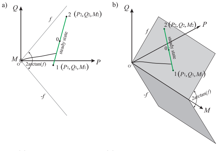
- domain assumption The loading trajectory remains inside the partial-slip wedge, so the contact never slides completely.
- domain assumption Bulk tension range is moderate: slip direction at each contact edge is the same during each half-cycle and is never reversed.
- domain assumption A steady state exists in which the permanent stick zone [−m,n] has the same extent just before every load reversal.
- standard math Known inversion formula for the Cauchy singular integral equation with weight w(x,a,c) is used.
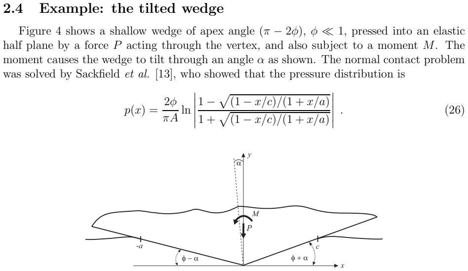
- domain assumption The tilted wedge normal-contact pressure solution from [13] is correct.
Cite this review
Pith. "Pith review of Steady state cyclic behaviour of a half-plane contact in partial slip subject to varying normal load, moment, shear load, and moderate differential bulk tension." pith.science (2026). https://pith.science/paper/5FPAUZZR
@misc{pith2026190807939,
  author       = {Pith},
  title        = {Pith review of: Steady state cyclic behaviour of a half-plane contact in partial slip subject to varying normal load, moment, shear load, and moderate differential bulk tension},
  year         = {2026},
  howpublished = {\url{https://pith.science/paper/5FPAUZZR}},
  note         = {Machine review of arXiv:1908.07939}
}
read the original abstract
A new solution for a general half-plane contact in the steady state is presented. The contacting bodies are subject to a set of constant loads - normal force, shear force and bulk tension parallel with the interface - together with an oscillatory set of the same quantities. Partial slip conditions are expected to ensue for a range of these quantities. In addition, the line of action of the normal load component does not necessarily need to pass the centre-line of the contact, thereby introducing a moment and asymmetry in the contact extent. This advancement enables a mapping to be formalised between the normal and tangential problem. An exact and easy to apply recipe is defined.
Figures
Figures from the paper (3 more)

Reference graph
Works this paper leans on
-
[1]
H. Andresen, D. Hills, J. Barber, J. V´ azquez, Frictional half-p lane contact problems subject to alternating normal and shear loads and tension in the st eady state, Int. Jnl. Solids Struct. (in press, DOI: j.ijsolstr.2019.03.025) (2019)
work page 2019
- [10]
-
[2]
H. Hertz, ¨ uber die ber¨ uhrung fester elastischer k¨ orper, Journal f¨ ur die reine und ange- wandte Mathematik 92 (1881) 156–171 (1881)
-
[3]
Cattaneo, Sul contato di due corpo elastici, Atti Accad
C. Cattaneo, Sul contato di due corpo elastici, Atti Accad. Na z. Lincei, Cl. Sci. Fis., Mat. Nat., Rend. 27 (1938) 342–348, 434–436, 474–478 (1938)
work page 1938
-
[4]
Mindlin, Compliance of elastic bodies in contact, AASME Trans
R. Mindlin, Compliance of elastic bodies in contact, AASME Trans. Jn l. Appl. Mech. 16 (1949) 259–268 (1949)
work page 1949
-
[5]
R. Mindlin, W. Mason, T. Osmer, H. Dereiewicz, Effect of an oscillatin g tangential force on the contact surfaces of elastic spheres, Proc. First Na t. Congress of Applied Mechanics (1951) 203–208 (1951)
work page 1951
-
[6]
R. Mindlin, H. Dereiewicz, Elastic spheres in contact under varying oblique forces, J. of Applied Mechanics 20 (1953) 327–344 (1953). 12
work page 1953
- [7]
Show all 13 references
-
[8]
J¨ ager, A new principle in contact mechanics, Jnl
J. J¨ ager, A new principle in contact mechanics, Jnl. Tribology 120 (1998) 677–684 (1998)
1998
-
[9]
Ciavarella, The generalised cattaneo partial slip plane contact problem, part i theory, part ii examples, Int
M. Ciavarella, The generalised cattaneo partial slip plane contact problem, part i theory, part ii examples, Int. Jnl. Solids Struct. 35 (1998) 2349–2378 (19 98)
1998
-
[11]
Hills, D
D. Hills, D. Nowell, A. Sackfield, Mechanics of Elastic Contacts, Bu tterworth- Heinemann, 1993 (1993)
1993
-
[12]
Sackfield, C
A. Sackfield, C. Truman, D. Hills, The tilted punch under normal a nd shear load (with application to fretting tests), Int. Jnl. Mech. Sci. 43 (2001) 1881 –1892 (2001)
2001
-
[13]
Sackfield, D
A. Sackfield, D. Dini, D. Hills, The tilted shallow wedge problem, Euro pean Journal of Mechanics A/Solids 24 (2005) 919–928 (2005). 13
2005
Reviewed August 14, 2026 · model on record in the stance chip above.
Discussion (0). Continue with ORCID to comment.