REVIEW 3 major objections 4 minor 30 references
Large-Angle, Broadband and Multifunctional Gratings Based on Directively Radiating Waveguide Scatterers
T0 review · 3 major / 4 minor · reviewed 2026-08-14 · deepseek-v4-flash
Pith's one-line read A single asymmetric slot-waveguide unit cell can deflect normally incident light into one chosen diffraction order with 94% efficiency at 47 degrees and 80% at 80 degrees, in full-wave simulation.
desk verdict A new unit-cell concept with credible full-wave efficiencies, but the abstract oversells the 80° result and the two-mode design rule is a rough heuristic rather than a predictive law. read the letter →
The pith
A machine-rendered reading of the paper's core claim, the machinery that carries it, and where it could break.
The reading
What carries the argument
The load-bearing object is the asymmetric slot-waveguide unit cell treated as a secondary radiator. The mechanism is two-mode interference: the incident light excites a fundamental guided mode with effective index $n_{\mathrm{eff},A}$ and a higher-order guided or radiation mode with effective index $n_{\mathrm{eff},B}$ close to $n_{\mathrm{air}}$. The identity $h_b = \lambda_0/(n_{\mathrm{eff},A} - n_{\mathrm{eff},B})$ gives the height for one full beat, and choosing the waveguide height near a half-beat makes the time-averaged Poynting vector tilt to one side, producing an asymmetric element radiation pattern with a null in the undesired orders. The design procedure is to compute the two effective indices from a 2D mode solver, set the initial height from the beat length, and then tune in full-wave simulation.
What would settle it
Fabricate the one-dimensional slot-waveguide grating of Figure 4 at the height given exactly by $h_b = \lambda_0/(n_{\mathrm{eff},A} - n_{\mathrm{eff},B})$ without the simulation tuning step, and measure the fraction of normally incident power that lands in the $m = -1$ transmitted order across the 120 nm band. If that efficiency falls well below the simulated 92% peak or the neighboring orders carry a significant share, the two-mode beat-length rule is not sufficient to set the structure height.
Extended reading notes
Core claim
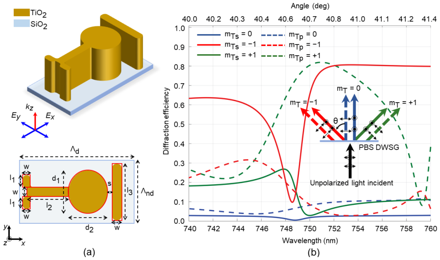
The central discovery is that the scattering pattern of a short waveguide section can be made unidirectional and steerable by exploiting the beating between two modes excited by the incident plane wave: the fundamental guided mode and a higher-order guided or radiation mode with effective index near that of air. The beat length $h_b = \lambda_0/(n_{\mathrm{eff},A} - n_{\mathrm{eff},B})$ sets the height at which the Poynting vector tilts toward the desired diffraction order, so the element factor has a maximum in that direction and nulls in the other orders. In simulation, one- and two-dimensional asymmetric slot-waveguide gratings yield efficiencies of 94.4% at 47 degrees, 91.6% at 50 degrees, 92% at 57 degrees, and about 80% at 80 degrees. The two-dimensional version also separates x- and y-polarized light by 80 degrees with about 80% efficiency and roughly 12 dB extinction. Because the element is non-resonant, the designs keep high efficiency over a fractional bandwidth of about 20 to 23 percent and tolerate variations in incidence angle.
Load-bearing premise
The two-mode interference model, with the infinite-waveguide beat length of Eq. 1, is assumed to fix the finite waveguide height, so open-end effects and extra modes are only small corrections that simulation tuning can absorb.
Editorial extensions
If this is right
- Large-angle diffraction can be achieved without high-aspect-ratio binary-blazed structures or resonant subwavelength elements: a single low-aspect-ratio slot-waveguide per period can hold above 80% absolute efficiency from roughly 40 to 80 degrees.
- The non-resonant design keeps above 80% efficiency over a roughly 120 nm band in the red for the one-dimensional design, a fractional bandwidth of about 23%, and tolerates oblique incidence along the negative-angle direction.
- A two-dimensional version can act as a flat polarization beamsplitter, directing x- and y-polarized beams into different first orders separated by 80 degrees with about 80% efficiency and roughly 12 dB extinction.
- The authors state that the same two-mode beating principle can be extended to reflective gratings and partially reflective-transmissive gratings, not only transmission gratings.
Reading between the lines
- If the beat-length rule survives experimental fabrication tolerances, the waveguide height itself becomes a control knob for deflection angle, so a supercell with graded heights could synthesize arbitrary wavefronts without resonant phase control, an extension the paper does not simulate.
- The polarization beamsplitter is presented only in simulation; a natural next step would be to fabricate it and verify the 12 dB extinction and 80% efficiency across the operating band, especially since the paper notes that fabrication errors have severely degraded efficiency in competing large-angle metagratings.
- The design formula depends only on two effective indices, so the same geometry should be scalable to other wavelength bands by rescaling dimensions and choosing a transparent high-index material, though the paper only reports visible and near-infrared TiO2 and Si designs.
Signed reviews
Editorial analysis
A structured set of objections, weighed in public.
Referee Report
Summary. The paper proposes 'Directive Waveguide Scatterer Gratings' (DWSGs), in which an asymmetric slot-waveguide unit cell scatters light directionally through interference between a low-order guided mode and a higher-order guided or radiation mode. A beat-length formula, Eq. (1), is used to estimate the waveguide height that produces the desired unidirectional scattering. The authors report full-wave simulated diffraction efficiencies of 92% at ~57° for a one-dimensional asymmetric slot-waveguide, 94.4% at ~47° for a two-dimensional design, and >80% over large-angle ranges for a multilayer variant. They also present a polarization beamsplitter with ~80% efficiency and an 80° separation angle. The paper emphasizes that these structures are non-resonant, broadband, and tolerant to incidence-angle variations, in contrast to resonant metasurface gratings.
Significance. If the reported efficiencies and design principle hold, DWSGs could offer a simpler, fabrication-friendly alternative to resonant metasurface gratings for large-angle diffraction, with potential impact in spectroscopy, flat optics, and beam steering. The paper's strengths are that the efficiency values are direct outputs of full-wave simulations, all structural parameters are explicitly listed, and the authors compare with prior metasurface-grating work and comment on fabrication constraints. The central physical picture is intuitive and supported by field plots. However, the quantitative validity of the design rule, the degree to which the reported performance is truly non-resonant, and the consistency between the abstract and the body are all areas that need attention before the claims can be fully accepted.
major comments (3)
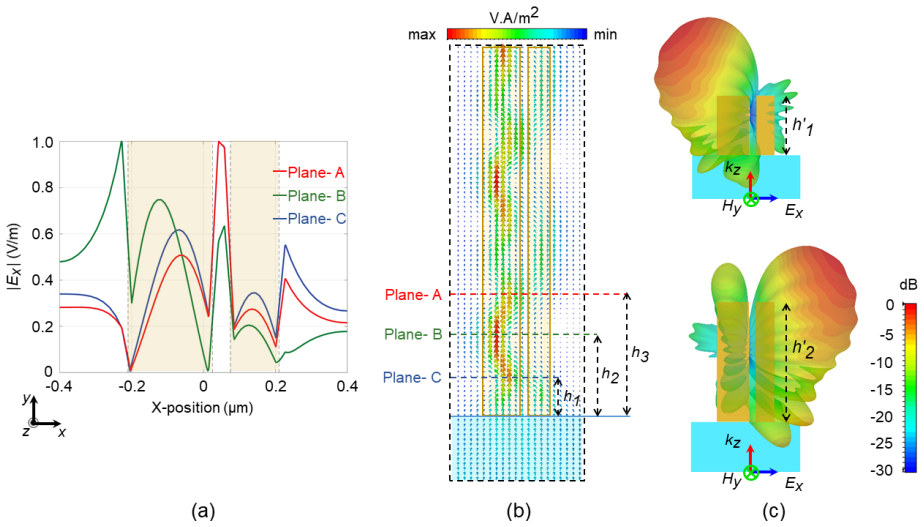
- [DWSG Designs and Results, Eq. (1), Figs. 4-6 and S6] The half-beat-length formula is not quantitatively predictive as presented. For the 1D asymmetric design (Fig. 4), the optimized structural height is 390 nm, whereas the reported half-beat length at λ = 670 nm is ~350 nm (Fig. 5), an 11% deviation; for the 2D design (Fig. 6), the structural height is 400 nm versus a half-beat of ~440 nm (Fig. S6), a 9% deviation. The paper states that the required height 'will vary slightly from eq 1' due to abruptly terminated open ends, but no criterion is given for how large a deviation is acceptable, and no quantitative test is provided that the two-mode model predicts either the optimum height or the far-field scattering pattern. I request a comparison of diffraction efficiency as a function of waveguide height against the predicted half-beat positions, or an argument showing that the optimized heights are within the tolerance of the design rule. Without this, the claim that the unit cell can be 'precisely tuned' via Eq. (1) is not established.
- [Discussion, second paragraph] The highest reported efficiency (94.4% at 47°) is obtained at λ = 585 nm, which is within ~3 nm of the sharp resonance peak at λ = 588 nm attributed to an in-plane guided mode. This is difficult to reconcile with the central claim that DWSGs are non-resonant and that their broadband operation follows from non-resonant scattering. The paper acknowledges that this resonance reduces the 2D design's fractional bandwidth to 20%, but the headline efficiency is nonetheless resonance-adjacent. Please quantify the non-resonant contribution, for example by showing efficiency versus wavelength away from the resonance or by demonstrating that the high efficiency persists when the resonance is suppressed, and restrict the 'non-resonant' claim to designs where it is actually supported.
- [Abstract and DWSG Designs and Results, Figs. 4, 7] The abstract's statement that the designs exhibit 'diffraction efficiencies ranging from 94% for a deflection angle of 47° to 80% for deflection angle of 80°' is not supported by any single grating simulation. For the 1D design (Fig. 4), the efficiency at ~82.5° is 50%; for the multilayer design, the text reports >80% over roughly 70°-80°, but not an exact 80% value at 80°; and the PBS (Fig. 7) separates two beams by 80° with 80% efficiency, with each beam deflected by only ~40°. Please rephrase the abstract to distinguish the deflection-angle range of the high-efficiency single-beam gratings from the beam-separation angle of the polarization beamsplitter.
minor comments (4)
- [Eq. (1)] Please define the subscripts A and B (lowest-order guided mode versus high-order guided or radiation mode) explicitly in the text before Eq. (1); the current notation is introduced only through the surrounding prose.
- [Figs. 5 and S6] The captions give open-ended waveguide-section heights h′1 = 440 nm and h′2 = 880 nm (Fig. 5) and h′1 = 475 nm and h′2 = 950 nm (Fig. S6), whereas the optimized structural heights are 390 nm (Fig. 4) and 400 nm (Fig. 6). Please clarify the relationship between these h′ values and the structural height used in the full-wave efficiency calculations.
- [Methods] Specify the wavelength at which the refractive indices n = 2.53 (TiO2) and n = 3.5 (Si) are evaluated, or state explicitly that dispersion was neglected in the simulations.
- [Throughout] The term 'non-diffractive period' is used in the discussion of the 2D designs without a definition; please state that this period is chosen small enough that only the zero order propagates along that lateral direction.
Circularity Check
No circularity: the design rule is a standard beat-length relation used only as an initial guess; all efficiencies come from openly reported full-wave optimization.
full rationale
I walked the paper's derivation chain and found no step in which a prediction or first-principles result reduces by construction to its own inputs. The central design relation, Eq. (1), h_b = lambda_0/(n_eff,A - n_eff,B), is a standard beat-length formula whose effective indices are independently computed with a mode solver and cross-checked in full-wave simulation. The paper explicitly states this beat length only provides the initial structural height, and that the final designs are optimized in CST Studio: 'The beat length calculated from the previous steps provided the structural height required for our initial design. Then, we optimized the design parameters of the waveguide to achieve suitable diffraction efficiency in CST Studio Frequency domain solver using Periodic Boundary Conditions.' The reported efficiencies of 94%, 92%, and 80% are simulation outputs of the optimized geometries, not quantities derived from Eq. (1) or implied by it. There are no fitted parameters being renamed as predictions, and no self-citations are used as load-bearing support; the cited references for mode equations and prior grating work are external. The admitted deviation of optimized heights from the simple beat-length estimate, and the paper's own note of a sharp resonance at lambda = 588 nm in the 2D design, weaken the quantitative and qualitative claims about 'precise tuning' and fully 'non-resonant' operation, but these are correctness and consistency concerns, not circularity. The derivation is therefore self-contained; the score is 0.
Assumptions & free parameters
free parameters (2)
- Waveguide height h =
390 nm (1D), 400 nm (2D), 390 nm (PBS)
- Minimum slot width s =
50 nm
assumptions (5)
- domain assumption Incident light on each unit cell is a plane wave because the beam width is much larger than the period.
- domain assumption The scattering is dominated by two modes: the lowest-order guided mode and one higher-order guided or radiation mode with effective index close to n_air.
- domain assumption The radiation mode decays negligibly over the few-wavelength waveguide height.
- standard math Pattern multiplication principle applies: total array pattern is the product of element factor and array factor.
- domain assumption Full-wave simulations in CST Studio and COMSOL Multiphysics accurately represent the electromagnetic response.
Cite this review
Pith. "Pith review of Large-Angle, Broadband and Multifunctional Gratings Based on Directively Radiating Waveguide Scatterers." pith.science (2026). https://pith.science/paper/DK65LL5F
@misc{pith2026190807988,
  author       = {Pith},
  title        = {Pith review of: Large-Angle, Broadband and Multifunctional Gratings Based on Directively Radiating Waveguide Scatterers},
  year         = {2026},
  howpublished = {\url{https://pith.science/paper/DK65LL5F}},
  note         = {Machine review of arXiv:1908.07988}
}
abstract
Conventional surface-relief gratings are inefficient at deflecting normally-incident light by large angles. This constrains their use in many applications and limits the overall efficiency of any optical instrument integrating gratings. Here, we demonstrate a simple approach for the design of diffraction gratings that can be highly efficient for large deflection angles, while also offering additional functionality. The gratings are composed of a unit cell comprising a vertically-oriented asymmetric slot-waveguide. The unit cell shows oscillating unidirectional scattering behavior that can be precisely tuned as a function of the waveguide length. This occurs due to interference between multiple modes excited by the incident light. In contrast to metasurface-based gratings with multiple resonant sub-elements, a periodic arrangement of such non-resonant diffracting elements allows for broadband operation and a strong tolerance for variations in angle of incidence. Full-wave simulations show that our grating designs can exhibit diffraction efficiencies ranging from 94% for a deflection angle of 47$^\circ$ to 80% for deflection angle of 80$^\circ$. To demonstrate the multifunctionality of our grating design technique, we have also proposed a flat polarization beamsplitter, which allows for the separation of the two orthogonal polarizations by 80$^\circ$, with an efficiency of 80%.
Figures


Figures from the paper (4 more)


Reference graph
Works this paper leans on
- [1]
-
[2]
IEEE Journal of quantum Electronics 1969, 5, 454--458
Treacy, E. IEEE Journal of quantum Electronics 1969, 5, 454--458
work page 1969
-
[3]
Dobson, S. L.; Sun, P.-c.; Fainman, Y. Applied optics 1997, 36, 4744--4748
work page 1997
-
[4]
IBM Journal of research and Development 1969, 13, 160--168
Brown, B.; Lohmann, A. IBM Journal of research and Development 1969, 13, 160--168
work page 1969
-
[5]
Applied physics letters 1970, 16, 523--525
Dakss, M.; Kuhn, L.; Heidrich, P.; Scott, B. Applied physics letters 1970, 16, 523--525
work page 1970
-
[6]
Swanson, G. J. Binary optics technology: theoretical limits on the diffraction efficiency of multilevel diffractive optical elements; 1991
work page 1991
- [7]
-
[8]
Optics letters 1982, 7, 578--580
Fujita, T.; Nishihara, H.; Koyama, J. Optics letters 1982, 7, 578--580
work page 1982
Show all 30 references
-
[9]
G.; Popov, E
Loewen, E. G.; Popov, E. Diffraction gratings and applications; CRC Press, 1997
1997
-
[10]
Optics letters 1998, 23, 1081--1083
Lalanne, P.; Astilean, S.; Chavel, P.; Cambril, E.; Launois, H. Optics letters 1998, 23, 1081--1083
1998
-
[11]
JOSA A 1999, 16, 1143--1156
Lalanne, P.; Astilean, S.; Chavel, P.; Cambril, E.; Launois, H. JOSA A 1999, 16, 1143--1156
1999
-
[12]
Laser & Photonics Reviews 2017, 11, 1600295
Lalanne, P.; Chavel, P. Laser & Photonics Reviews 2017, 11, 1600295
2017
-
[13]
L.; Hooper, I
Meinzer, N.; Barnes, W. L.; Hooper, I. R. Nature Photonics 2014, 8, 889--898
2014
-
[14]
I.; Miroshnichenko, A
Kuznetsov, A. I.; Miroshnichenko, A. E.; Brongersma, M. L.; Kivshar, Y. S.; Luk’yanchuk, B. Science 2016, 354, aag2472
2016
-
[15]
B.; Boltasseva, A
Khurgin, J. B.; Boltasseva, A. MRS bulletin 2012, 37, 768--779
2012
-
[16]
Sell, D.; Yang, J.; Doshay, S.; Yang, R.; Fan, J. A. Nano letters 2017, 17, 3752--3757
2017
-
[17]
F.; Fu, Y
Khaidarov, E.; Hao, H.; Paniagua-Dom \' nguez, R.; Yu, Y. F.; Fu, Y. H.; Valuckas, V.; Yap, S. L. K.; Toh, Y. T.; Ng, J. S. K.; Kuznetsov, A. I. Nano letters 2017, 17, 6267--6272
2017
-
[18]
R.; Allen, M.; Allen, J.; Wenner, B.; Shvets, G
Fan, Z.; Shcherbakov, M. R.; Allen, M.; Allen, J.; Wenner, B.; Shvets, G. ACS Photonics 2018, 5, 4303--4311
2018
-
[19]
In contrast, DWSG specifically and unambiguously describes the physics of the structure that suppresses all the diffraction orders except the one that is desired
Since the term ``meta'' generally refers to homogenizable structures, the terminology ``metagrating'' used by others is not appropriate here. In contrast, DWSG specifically and unambiguously describes the physics of the structure that suppresses all the diffraction orders exce...
-
[20]
Schelkunoff, S. A. The Bell System Technical Journal 1943, 22, 80--107
1943
-
[21]
Haupt, R. L. Antenna arrays: a computational approach; John Wiley & Sons, 2010
2010
-
[22]
W.; Love, J
Snyder, A. W.; Love, J. Optical waveguide theory; Springer Science & Business Media, 2012
2012
-
[23]
D.; Steier, W
Laakmann, K. D.; Steier, W. H. Applied optics 1976, 15, 1334--1340
1976
-
[24]
In the spatially steady-state region, only the guided modes exist
The radiation mode is weakly guiding and thus decays in the spatially transient region where we observe the beating effect. In the spatially steady-state region, only the guided modes exist. Because the height of the waveguides considered in our examples are a few wavelengths ...
-
[25]
Although modes in an asymmetric waveguides are not strictly even or odd, we can define an even mode when the transverse field components have same polarity outside the both extreme edges of the waveguide and odd modes when they have opposite polarity
-
[26]
Optics Communications 2009, 282, 324--328
Ma, C.; Zhang, Q.; Van Keuren, E. Optics Communications 2009, 282, 324--328
2009
-
[27]
R.; Xu, Q.; Barrios, C
Almeida, V. R.; Xu, Q.; Barrios, C. A.; Lipson, M. Optics letters 2004, 29, 1209--1211
2004
-
[28]
Optics express 2008, 16, 13824--13830
Pietarinen, J.; Vallius, T. Optics express 2008, 16, 13824--13830
2008
-
[29]
Nature nanotechnology 2015, 10, 937--943
Arbabi, A.; Horie, Y.; Bagheri, M.; Faraon, A. Nature nanotechnology 2015, 10, 937--943
2015
-
[30]
DWSG_illustration
Chen, W. T.; Zhu, A. Y.; Sanjeev, V.; Khorasaninejad, M.; Shi, Z.; Lee, E.; Capasso, F. Nature nanotechnology 2018, 13, 220--226 mcitethebibliography achemso-demo.bib0000664000000000000000000003716513527274225012622 0ustar rootroot@ARTICLE Abernethy2003, author = Colin D. Aber...
2018
Reviewed August 14, 2026 · model on record in the stance chip above.
Discussion (0). Continue with ORCID to comment.