REVIEW 3 major objections 4 minor 29 references
Flexible Trinocular: Non-rigid Multi-Camera-IMU Dense Reconstruction for UAV Navigation and Mapping
T0 review · 3 major / 4 minor · reviewed 2026-08-14 · deepseek-v4-flash
Pith's one-line read This paper aims to show that a fast fixed-wing UAV can estimate its own time-varying trinocular baseline well enough to produce long-range dense depth maps for navigation and mapping.
desk verdict Genuine incremental step with real flight tests, but held-out evaluation and quantitative pose/depth error are missing; the central accuracy claim is not yet proven. read the letter →
The pith
A machine-rendered reading of the paper's core claim, the machinery that carries it, and where it could break.
The reading
What carries the argument
The load-bearing object is a relative extended Kalman filter for each wing-center camera pair, with a state that includes the relative rotation quaternion, translation, angular velocities, linear accelerations, and IMU biases. Its job is to stay close to the true wing-to-center transform between frames: the relative IMU propagation gives the prior, the photometric refinement corrects it with image intensities, and the probabilistic wing model—a Gaussian mean and covariance for the same transform learned from in-flight fiducial-marker observations—pulls the estimate back when vision fails. The photometric step is what makes the translation full-scale rather than up-to-scale, which is the property that turns a flexible baseline into metric depth.
What would settle it
Fly the platform through a maneuver envelope not represented in the calibration flight, while independently measuring the wing-camera poses from the side cameras' fiducial markers; if the marker-derived poses systematically drift outside the EKF's predicted uncertainty as airspeed or gust level increases, the fixed wing-model prior is not generalizing and the central claim collapses.
Extended reading notes
Core claim
The discovery is that the time-varying relative pose of cameras mounted on a flexible fixed-wing aircraft can be estimated tightly enough to generate dense depth maps at ranges unreachable by a rigid small-baseline rig, and that this can be done in real time with low-cost sensors. The estimator is an EKF in relative form whose state covers, for each wing camera, the rotation and translation to the center camera, angular velocities, accelerations, and IMU biases. The EKF propagates the baseline with IMU data, then a photometric sparse image alignment—using the predicted pose to project center-camera feature patches into the wing image and minimizing the intensity difference with a constrained Gauss-Newton solver—provides a full-scale pose update. That update is fused with a Gaussian wing model, a mean and covariance of the wing-to-center transform calibrated in flight via fiducial markers observed by side cameras. With the corrected poses, stereo rectification and block matching produce depth maps from the full baseline and from the half baselines, and the center camera's rigid link to the autopilot lets those maps be geo-referenced.
Load-bearing premise
The whole estimate leans on a fixed probabilistic wing model learned from one in-flight calibration, and if that prior does not match the deformation on the flight being evaluated, the baseline estimates will be biased.
Editorial extensions
If this is right
- A fixed-wing UAV with a wide flexible baseline can produce depth maps at ranges where a rigid in-fuselage stereo rig would have one-pixel disparity limits, making long-range navigation feasible with low-cost sensors.
- The same three cameras give two half-baseline pairs for near-field tasks such as landing and obstacle avoidance, and one full-baseline pair for distant terrain, without extra hardware.
- Because the center camera is rigidly attached to the fuselage and autopilot, the depth maps can be transformed directly into a geo-referenced map for local replanning, rather than serving only reactive avoidance.
- The wing-model calibration using side cameras and fiducial markers is a one-time procedure per UAV type, so the operational sensor suite remains just the three cameras and IMUs.
- The modular EKF and per-frame runtime mean the pipeline can run at 10 Hz on small onboard computers and can accommodate extra camera-IMU rigs to widen the field of view.
Reading between the lines
- A clear next experiment is to split calibration and evaluation flights: learn the wing-model Gaussian on one flight, then fly on a different day or airspeed regime and check whether EKF poses stay inside the filter's predicted uncertainty; this would settle whether the fixed prior generalizes.
- Conditioning the wing model on airspeed or measured load factor should remove the largest expected bias, since the paper's own take-off data show the relative transform shifting abruptly and the future-work notes already point toward a cantilever-beam model with airspeed as an input.
- The modular filter structure invites adding extra camera-IMU pairs, such as on the tail or nose, to widen the field of view or add short-range baselines without re-deriving the estimator; each pair is just another relative EKF.
Signed reviews
Editorial analysis
A structured set of objections, weighed in public.
Referee Report
Summary. This paper proposes a visual-inertial framework for estimating the time-varying relative pose between three cameras mounted on a fixed-wing UAV, where the outer cameras are on flexible wings and the center camera is in the fuselage. The relative pose between each wing camera and the center camera is estimated by an EKF that fuses relative IMU measurements, a photometric sparse image alignment term, and a probabilistic wing model learned from in-flight observations. The estimated poses are used to rectify image pairs and compute depth maps by block matching. The paper reports a wing-model calibration procedure using April tags and side cameras, hardware integration, real-world flight experiments, and runtime measurements. The central claim is that this non-rigid trinocular setup provides long-range depth estimation beyond what a rigid small-baseline rig can offer.
Significance. If the central claim holds, the work is a useful step for fixed-wing UAV perception, as it addresses a real deployment constraint: wide-baseline stereo on aeroelastically deforming wings. The paper's strengths are the complete system integration on a real platform, the hardware-synchronized multi-camera-IMU sensor design, the in-flight wing-model calibration procedure, and the demonstration that a photometric update with a good prior runs efficiently on the tested hardware. However, the current evidence is largely qualitative. The depth maps and pose estimates are shown as images, but no quantitative comparison against independent ground truth is provided, and the relationship between the calibration flight and the evaluation flight is not stated. These gaps directly affect the strength of the main claim that the estimated baseline is accurate enough for long-range depth estimation.
major comments (3)
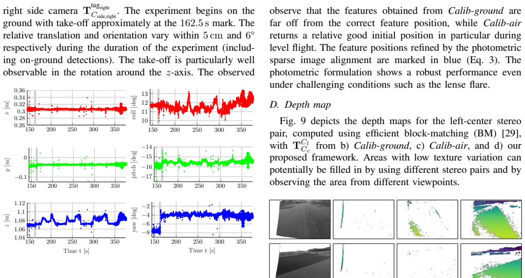
- [Sec. VI-C and VI-D, Figs. 8 and 9] The core claim that the EKF accurately estimates the time-varying wing-to-center baseline is supported only qualitatively. The paper shows reprojected features and sample depth maps, but it does not report any quantitative error metric for the estimated relative pose TCj/Cc or for the depth maps. Given that the motivation is long-range depth accuracy, please add numbers: for example, root-mean-square or median errors of the estimated relative translation and rotation against an independent reference, and depth error or disparity error statistics when ground-truth or a held-out reference is available.
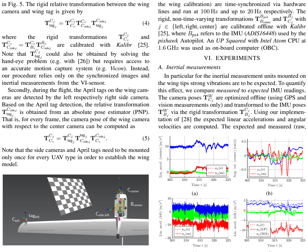
- [Sec. IV-C and Sec. VI-B] The manuscript does not state whether the flight used to build the probabilistic wing model is the same flight used for the qualitative demonstrations in Figs. 8 and 9. If the 'Calib-air' prior is derived from the same flight on which the system is then evaluated, the EKF result is partly fit to the deformation of that flight, and the claimed robustness across aerodynamic conditions is untested. Please state explicitly whether the calibration and evaluation flights are distinct, and ideally evaluate on a held-out flight or compare the EKF estimate frame-by-frame against the independent April-tag/side-camera reference from Sec. IV-C.
- [Eq. (3) and Sec. IV-A] The wing-model prior appears both as the motion prior in the photometric objective (Eq. (3)) and as the Gaussian fused in the EKF, but the manuscript does not specify how the prior covariance is used or how its weight is set relative to the vision update. Since a too-confident prior would dominate the visual-inertial measurements and effectively reproduce the calibration fit, please clarify the fusion formulation, report the covariance values used, and provide a sensitivity analysis to the prior weight.
minor comments (4)
- [Table I] The runtime in Table I is measured on an Intel i7-4800MQ, while the onboard computer is an UP Squared with an Intel Atom at 1.6 GHz; please clarify whether the stated 'some margin' conclusion applies to the actual onboard platform or only to the more powerful comparison machine.
- [Sec. IV-A] The state vector in Eq. (1) includes IMU biases for both cameras, but the propagation and update equations for these biases are not given in the paper; citing [19] is acceptable, but a brief description of how the biases are modeled would improve readability.
- [Fig. 9] The depth maps in Fig. 9 are single-shot examples without a color scale or quantitative depth legend, making it hard for the reader to judge the actual depth range or to compare the proposed method against the two priors beyond visual inspection.
- [General] There are a few typographical and formatting issues, such as the text running into figure captions in Sec. VI-B ('The observed 150 200 250 300 3500.26'), which should be cleaned up in the final version.
Circularity Check
No significant circularity: the wing-model prior is an explicit calibration input, and the EKF estimate is driven by independent IMU and photometric updates; the lack of held-out validation is an evidence gap, not circularity.
full rationale
The paper's claimed derivation chain is: (i) calibrate rigid transforms with Kalibr; (ii) observe the wing-to-center transformation in flight via April tags to form a Gaussian wing model (Sec. IV-C, Eqs. 4-5); (iii) run a relative EKF that propagates with IMU and updates with photometric sparse image alignment, using the wing model only as a regularizing prior (Eq. 3); (iv) generate depth maps from the EKF-optimized poses. The wing-model mean and covariance are an explicit input, not the output of the EKF, and the photometric cost and relative IMU propagation provide independent measurements of the same quantity. Therefore no fitted parameter is renamed as a prediction, and the estimated baseline is not equal by construction to the wing model. The paper's reliance on [1] for the wing-model concept and [19] for the EKF formulation is not load-bearing circularity: Sec. IV-C gives an independent calibration procedure for the Gaussian prior, and [19] is an established relative-EKF formulation rather than an unverified self-citation chain. The absence of a quantitative held-out comparison of the estimated relative pose against an independent reference (e.g., a separate flight or motion-capture truth) weakens the evidence for generalization, but that is a validation gap, not a circularity. No equation in the paper reduces the claimed output to its inputs.
Assumptions & free parameters
free parameters (2)
- Probabilistic wing model mean and covariance =
not given numerically; in-flight offsets up to ~5 cm and 6 deg observed
- IMU low-pass filter cutoff frequency =
5 Hz
assumptions (3)
- domain assumption Center camera is aligned with the map throughout the paper.
- domain assumption Wing deformation relative to the fuselage follows a Gaussian distribution captured by a constant mean and covariance.
- domain assumption Features with corresponding depth estimates tracked in the center camera are available for camera-camera alignment.
Cite this review
Pith. "Pith review of Flexible Trinocular: Non-rigid Multi-Camera-IMU Dense Reconstruction for UAV Navigation and Mapping." pith.science (2026). https://pith.science/paper/OZCTQY2A
@misc{pith2026190808891,
  author       = {Pith},
  title        = {Pith review of: Flexible Trinocular: Non-rigid Multi-Camera-IMU Dense Reconstruction for UAV Navigation and Mapping},
  year         = {2026},
  howpublished = {\url{https://pith.science/paper/OZCTQY2A}},
  note         = {Machine review of arXiv:1908.08891}
}
read the original abstract
In this paper, we propose a visual-inertial framework able to efficiently estimate the camera poses of a non-rigid trinocular baseline for long-range depth estimation on-board a fast moving aerial platform. The estimation of the time-varying baseline is based on relative inertial measurements, a photometric relative pose optimizer, and a probabilistic wing model fused in an efficient Extended Kalman Filter (EKF) formulation. The estimated depth measurements can be integrated into a geo-referenced global map to render a reconstruction of the environment useful for local replanning algorithms. Based on extensive real-world experiments we describe the challenges and solutions for obtaining the probabilistic wing model, reliable relative inertial measurements, and vision-based relative pose updates and demonstrate the computational efficiency and robustness of the overall system under challenging conditions.
Figures


Figures from the paper (4 more)


Reference graph
Works this paper leans on
-
[1]
T. Hinzmann, T. Taubner, and R. Siegwart, “Flexible stereo: Con- strained, non-rigid, wide-baseline stereo vision for fixed-wing aerial platforms,” in IEEE International Conference on Robotics and Au- tomation (ICRA), pp. 2550–2557, May 2018
work page 2018
-
[2]
Robust visual inertial odometry using a direct EKF-based approach,
M. Bloesch, S. Omari, M. Hutter, and R. Siegwart, “Robust visual inertial odometry using a direct EKF-based approach,” in IEEE/RSJ International Conference on Intelligent Robots and Systems (IROS) , pp. 298–304, IEEE, 2015
work page 2015
-
[3]
Keyframe-based visual–inertial odometry using nonlinear optimiza- tion,
S. Leutenegger, S. Lynen, M. Bosse, R. Siegwart, and P. Furgale, “Keyframe-based visual–inertial odometry using nonlinear optimiza- tion,” The International Journal of Robotics Research , vol. 34, no. 3, pp. 314–334, 2015
2015
-
[4]
ORB-SLAM2: an open-source SLAM system for monocular, stereo and RGB-D cameras,
R. Mur-Artal and J. D. Tard ´os, “ORB-SLAM2: an open-source SLAM system for monocular, stereo and RGB-D cameras,” IEEE Transac- tions on Robotics , vol. 33, no. 5, pp. 1255–1262, 2017
work page 2017
-
[5]
Efficient multi- camera visual-inertial SLAM for micro aerial vehicles,
S. Houben, J. Quenzel, N. Krombach, and S. Behnke, “Efficient multi- camera visual-inertial SLAM for micro aerial vehicles,” in IEEE/RSJ International Conference on Intelligent Robots and Systems (IROS) , pp. 1616–1622, IEEE, 2016
work page 2016
-
[6]
Robust stereo visual inertial odometry for fast autonomous flight,
K. Sun, K. Mohta, B. Pfrommer, M. Watterson, S. Liu, Y . Mulgaonkar, C. J. Taylor, and V . Kumar, “Robust stereo visual inertial odometry for fast autonomous flight,” IEEE Robotics and Automation Letters , vol. 3, no. 2, pp. 965–972, 2018
work page 2018
-
[7]
Omnidirectional visual obstacle detection using em- bedded FPGA,
P. Gohl, D. Honegger, S. Omari, M. Achtelik, M. Pollefeys, and R. Siegwart, “Omnidirectional visual obstacle detection using em- bedded FPGA,” in IEEE/RSJ International Conference on Intelligent Robots and Systems (IROS) , pp. 3938–3943, IEEE
-
[8]
M. M ¨uller, F. Steidle, M. J. Schuster, P. Lutz, M. Maier, S. Stoneman, T. Tomic, and W. St ¨urzl, “Robust visual-inertial state estimation with multiple odometries and efficient mapping on an MA V with ultra- wide FOV stereo vision,” in IEEE/RSJ International Conference on Intelligent Robots and Systems (IROS) , pp. 3701–3708, IEEE, 2018
work page 2018
Show all 29 references
-
[9]
Pushbroom stereo for high-speed nav- igation in cluttered environments,
A. J. Barry and R. Tedrake, “Pushbroom stereo for high-speed nav- igation in cluttered environments,” in IEEE International Conference on Robotics and Automation (ICRA) , pp. 3046–3052, IEEE, 2015
2015
-
[10]
Online calibration of stereo rigs for long-term autonomy,
M. Warren, D. McKinnon, and B. Upcroft, “Online calibration of stereo rigs for long-term autonomy,” inIEEE International Conference on Robotics and Automation (ICRA) , pp. 3692–3698, IEEE, 2013
2013
-
[11]
Long-range stereo visual odometry for extended altitude flight of unmanned aerial vehicles,
M. Warren, P. Corke, and B. Upcroft, “Long-range stereo visual odometry for extended altitude flight of unmanned aerial vehicles,” The Intern. J. of Robotics Research, vol. 35, no. 4, pp. 381–403, 2016
2016
-
[12]
Modal-based camera correction for large pitch stereo imaging,
P. Lanier, N. Short, K. Kochersberger, and L. Abbott, “Modal-based camera correction for large pitch stereo imaging,” in Structural Dy- namics, Volume 3, pp. 1225–1238, Springer, 2011
2011
-
[13]
Stereovision Correction Using Modal Analysis,
P. Lanier, “Stereovision Correction Using Modal Analysis,” Master’s thesis, Virginia Polytechnic Institute and State University, 2010
2010
-
[14]
3-D Point Cloud Generation from Rigid and Flexible Stereo Vision Systems,
N. J. Short, “3-D Point Cloud Generation from Rigid and Flexible Stereo Vision Systems,” Master’s thesis, Virginia Tech, 2009
2009
-
[15]
Decoupling of airborne dynamic bending deformation angle and its application in the high-accuracy transfer alignment process,
P. Yang, X. Chen, and J. Wang, “Decoupling of airborne dynamic bending deformation angle and its application in the high-accuracy transfer alignment process,” vol. 19, p. 214, Multidisciplinary Digital Publishing Institute, 2019
2019
-
[16]
Collaborative stereo,
M. W. Achtelik, S. Weiss, M. Chli, F. Dellaert, and R. Siegwart, “Collaborative stereo,” inIntelligent Robots and Systems (IROS), 2011 IEEE/RSJ International Conference on , pp. 2242–2248, IEEE, 2011
2011
-
[17]
VI-RPE: visual- inertial relative pose estimation for aerial vehicles,
L. Teixeira, F. Maffra, M. Moos, and M. Chli, “VI-RPE: visual- inertial relative pose estimation for aerial vehicles,” IEEE Robotics and Automation Letters , vol. 3, no. 4, pp. 2770–2777, 2018
2018
-
[18]
Collaborative 6DoF Relative Pose Estimation for two UA Vs with Overlapping Fields of View,
M. Karrer, M. Agarwal, M. Kamel, R. Siegwart, and M. Chli, “Collaborative 6DoF Relative Pose Estimation for two UA Vs with Overlapping Fields of View,” in IEEE International Conference on Robotics and Automation (ICRA) , 2018
2018
-
[19]
Col- laborative Stereo,
M. Achtelik, S. Weiss, M. Chli, F. Dellaert, and R. Siegwart, “Col- laborative Stereo,” in Proceedings of the IEEE/RSJ Conference on Intelligent Robots and Systems , 2011
2011
-
[20]
SVO: semidirect visual odometry for monocular and multicamera systems,
C. Forster, Z. Zhang, M. Gassner, M. Werlberger, and D. Scaramuzza, “SVO: semidirect visual odometry for monocular and multicamera systems,” IEEE Trans. Robotics , vol. 33, no. 2, pp. 249–265, 2017
2017
-
[21]
Monocular visual-inertial SLAM for fixed-wing UA Vs using sliding window based nonlinear optimization,
T. Hinzmann, T. Schneider, M. Dymczyk, A. Schaffner, S. Lynen, R. Siegwart, and I. Gilitschenski, “Monocular visual-inertial SLAM for fixed-wing UA Vs using sliding window based nonlinear optimization,” in Intern. Symp. on Visual Computing , pp. 569–581, Springer, 2016
2016
-
[22]
Robust map generation for fixed- wing UA Vs with low-cost highly-oblique monocular cameras,
T. Hinzmann, T. Schneider, M. Dymczyk, A. Melzer, T. Mantel, R. Siegwart, and I. Gilitschenski, “Robust map generation for fixed- wing UA Vs with low-cost highly-oblique monocular cameras,” in IEEE/RSJ International Conference on Intelligent Robots and Systems (IROS), pp. 3261–...
2016
-
[23]
Svo: Fast semi-direct monocular visual odometry,
C. Forster, M. Pizzoli, and D. Scaramuzza, “Svo: Fast semi-direct monocular visual odometry,” in 2014 IEEE international conference on robotics and automation (ICRA) , pp. 15–22, IEEE, 2014
2014
-
[24]
A compact algorithm for rectification of stereo pairs,
A. Fusiello, E. Trucco, and A. Verri, “A compact algorithm for rectification of stereo pairs,” Machine Vision and Applications, vol. 12, pp. 16–22, Jul 2000
2000
-
[25]
Extending kalibr: Calibrating the extrinsics of multiple IMUs and of individual axes,
J. Rehder, J. Nikolic, T. Schneider, T. Hinzmann, and R. Siegwart, “Extending kalibr: Calibrating the extrinsics of multiple IMUs and of individual axes,” in IEEE International Conference on Robotics and Automation (ICRA), pp. 4304–4311, May 2016
2016
-
[26]
Furrer, M
F. Furrer, M. Fehr, T. Novkovic, H. Sommer, I. Gilitschenski, and R. Siegwart, Evaluation of Combined Time-Offset Estimation and Hand-Eye Calibration on Robotic Datasets . Cham: Springer Inter- national Publishing, 2017
2017
-
[27]
A synchronized visual-inertial sensor system with FPGA pre-processing for accurate real-time SLAM,
J. Nikolic, J. Rehder, M. Burri, P. Gohl, S. Leutenegger, P. T. Furgale, and R. Siegwart, “A synchronized visual-inertial sensor system with FPGA pre-processing for accurate real-time SLAM,” in IEEE Interna- tional Conf. on Robotics and Automation (ICRA) , pp. 431–437, 2014
2014
-
[28]
Computing velocities and accelerations from a pose time sequence in three-dimensional space,
F. Sittel, J. M ¨uller, and W. Burgard, “Computing velocities and accelerations from a pose time sequence in three-dimensional space,” Tech. Rep. 272, University of Freiburg, Department of Computer Science, 2013
2013
-
[29]
The OpenCV Library,
G. Bradski, “The OpenCV Library,” Dr. Dobb’s Journal: Software Tools for the Professional Programmer, vol. 25, no. 11, pp. 120–123, 2000
2000
Reviewed August 14, 2026 · model on record in the stance chip above.
Discussion (0). Continue with ORCID to comment.