REVIEW 5 major objections 6 minor 1 cited by
Enabling steep slope walking on Husky using reduced order modeling and quadratic programming
T0 review · 5 major / 6 minor · reviewed 2026-08-12 · deepseek-v4-flash
Pith's one-line read A VLIP model with center-of-mass thrusters plus QP-MPC tracks a 40-degree slope in simulation, and the paper argues the forces transfer to full dynamics.
desk verdict Modest simulation-only VLIP/MPC extension for thruster-assisted steep-slope walking, undermined by an unsupported 'seamless transfer' claim that the paper's own conclusion contradicts. read the letter →
The pith
A machine-rendered reading of the paper's core claim, the machinery that carries it, and where it could break.
The reading
What carries the argument
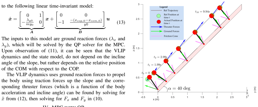
The central object is a modified Variable Length Inverted Pendulum (VLIP): a point mass connected to a fixed center-of-pressure point on the slope, with an external thruster force at the mass and ground reactions at the center of pressure. The zero-moment-point equation at the center of mass reduces the planar dynamics to the linear time-invariant model in Eq. (13), whose state is $(x_{\text{com}}, \dot{x}_{\text{com}})$ and whose inputs are ground reaction forces. The quadratic-programming MPC with friction-cone constraints is the mechanism that turns this model into a controller, and the paper argues that because the center of pressure can be placed anywhere inside the support polygon by distributing forces between the two contact legs, the thruster wrench from the VLIP can be handed to the full dynamics.
What would settle it
Run the same QP-computed ground reaction and thruster force profiles on the full Husky reduced-order model (HROM) with no-slip feet and posture-based thrust vectoring, and check whether the body follows the reference trajectory; if the full dynamics diverge, or if the required COP lies outside the support polygon, the central transferability claim fails. Alternatively, on hardware, measure whether the actual thruster wrench from the ducted fans matches the commanded $F_x$ and $F_y$ within the friction cone while attempting a 40-degree slope walk.
Extended reading notes
Core claim
The slope angle drops out of the reduced-order dynamics, leaving a linear time-invariant system whose behavior depends only on the relative position of the center of mass and the center of pressure. Solving the zero-moment-point equation about the center of mass under a constant height $¥ddot{y}=0$ yields $\ddot{x}_{\text{com}} = -(x_{\text{cop}}-x_{\text{com}})\lambda_y/(m y_0) - \lambda_x/m$, and the ground reaction forces $\lambda_x,\lambda_y$ become the inputs. The MPC then chooses these inputs over a horizon to minimize tracking error subject to bounds and the friction cone $\lambda_{y,k} > \lambda_{\min,n}$, $|\lambda_{x,k}| \le \mu_s \lambda_{y,k}$. In simulation on a 40-degree slope the optimizer finds feasible forces, the body tracks the reference position and velocity, and the implied thruster forces point in directions consistent with the wing-assisted inclined running intuition that legs supply traction while thrusters offload normal force.
Load-bearing premise
The center of pressure is assumed known, fixed, and controllable anywhere inside the support polygon, and the commanded thruster forces are assumed physically realizable by pitching the robot body; if either fails on the real Husky, the simulated 40-degree tracking would not transfer to hardware.
Editorial extensions
If this is right
- The reduced-order model is linear and the QP solver takes about 65 microseconds per call, so the controller is fast enough for real-time implementation on the robot's onboard computer.
- Ground reaction forces in the VLIP are independent of slope angle, so a single tuning of the MPC could apply to different inclines without re-deriving the model.
- The framework gives an explicit split of roles: legs provide traction through friction-cone-respecting ground forces, while thrusters offload normal force and help drive acceleration up steep slopes.
- The same QP formulation can be extended to 3D movements and whole-body control, as the paper identifies as future work.
- The approach offers a path to dynamic two-point contact gaits on steep slopes, going beyond the static three-foot-contact gaits used by earlier slope-walking controllers.
Reading between the lines
- The fixed-COP assumption is the main gap: the paper does not simulate the full HROM or hardware, so the claim that the thruster wrench 'can be seamlessly transferred' is an extrapolation; I would test robustness by perturbing the COP within the support polygon and measuring tracking degradation.
- The constant normal force result (normal ground reaction stays at $\lambda_{\min,n}$ because of the quadratic cost) suggests the optimizer actively offloads weight to the thrusters, which implies the achievable range of slope angles is bounded by propeller force limits.
- A natural extension is to replace the fixed-foothold heuristic with online foothold or step-timing optimization, which would let the same VLIP-QP framework handle irregular terrain and discrete contact switches.
- The decoupling of slope angle from the reduced-order dynamics means the controller could be reused across terrains without retuning, provided the COP can still be regulated.
Editorial analysis
A structured set of objections, weighed in public.
Referee Report
Summary. The paper proposes a planar modified Variable Length Inverted Pendulum (VLIP) model with thruster forces applied at the center of mass, and a QP-based MPC that computes optimal ground reaction forces and thruster forces to track a reference trajectory on a 40-degree slope. The authors simulate this reduced-order model in MATLAB, report tracking performance, friction-cone satisfaction, and qpSWIFT solve times, and claim that the resulting forces can be seamlessly transferred to the full Husky dynamics. The paper concludes by listing future work needed for hardware implementation, including kinematic and dynamic constraints, body pitch/roll thrust vectoring, and thrust regeneration via posture manipulation.
Significance. If the reduced-order control framework were validated against the full-order Husky model or hardware, it would be a useful step toward thruster-assisted steep-slope locomotion, building on established VLIP and QP-MPC techniques. The paper's strengths are its simple, real-time-compatible formulation, explicit friction-cone constraints in the optimization, and a slope-independent state model that depends only on the COP-COM offset. However, the current evidence is limited to a simulation of the reduced-order model, in which the thruster forces are computed from the same equations of motion used to propagate the state, so the results demonstrate internal consistency rather than independent predictive validity. The manuscript's own conclusion contradicts the strong transferability claim in Section IV, and the simulation parameters are not fully reported, which limits reproducibility.
major comments (5)
- [Section III, Eq. (13)] The linearized dynamics in Eq. (13) are inconsistent with Eq. (12). Using x_cop - x_com = (x_cop,0 - x_com,0) - (x_com - x_com,0), Eq. (12) linearizes to A(2,1) = +λ_y0/(m y0) and B(2,2) = -(x_cop,0 - x_com,0)/(m y0), whereas the paper prints A(2,1) = -λ_y0/(m y0) and B(2,2) = -(x_cop,0 - x_com,0)/y0. The sign error changes the open-loop pole locations, and the missing factor 1/m rescales the control input. Unless a different normalization is intended but not stated, the QP in Section IV is built on a different model than the one derived in Section III.
- [Section IV, Eq. (18)] The friction-cone constraint is one-sided. For positive normal forces λ_y,k ≥ λ_minn > 0, the correct no-slip condition is |λ_x,k| ≤ μ_s λ_y,k, i.e., -μ_s λ_y,k ≤ λ_x,k ≤ μ_s λ_y,k. The printed condition λ_x,k < μ_s |λ_y,k| imposes only an upper bound on λ_x and permits arbitrarily large negative tangential forces, which violates the no-slip assumption and undermines the claim that the QP output is constraint-admissible.
- [Section IV, last paragraph; Section VI] The claim that the QP-derived thruster forces 'can be seamlessly transferred to the full dynamics' is not supported by the manuscript. The simulation in Section V is run on the planar VLIP model, not on the HROM described in Section II, and no mapping from the commanded ground reaction and thruster forces to joint torques, leg lengths, body orientation, or the thrust-vectoring mechanism is provided. The paper's own conclusion states that 'strictly implementing the kinematic and dynamics constraints would be required,' including body pitch and roll for thrust vectoring and a method of thrust regeneration. The transfer claim should be removed or substantiated with at least a full-HROM simulation.
- [Sections III and V] The assumption that the COP is known, fixed, and controllable anywhere within the support polygon is load-bearing but never validated against the four-legged HROM. The MPC commands a scalar offset (x_cop - x_com) through the B matrix, and the resulting thruster forces are two-dimensional; realizing both on the actual robot requires posture manipulation and thrust vectoring that the paper explicitly defers to future work. The simulation therefore demonstrates internal feasibility of the reduced-order model, not feasibility on Husky.
- [Section V] The simulation results are not reproducible as reported. The MPC weights Q and R, prediction horizon n_h, discretization time step, λ_minn, μ_s, the reference trajectory, and the COP update rule are not specified; only the slope angle and the solver's average solve time are given. Without these parameters, the tracking and constraint-satisfaction results in Figs. 4-7 cannot be independently checked.
minor comments (6)
- [Section I] The paper structure says 'In Section 1... Section 2...' but the actual sections are labeled with Roman numerals II-V; renumber the outline accordingly.
- [Section IV] The constraint line 'Umin and Umin' should read 'Umin and Umax'.
- [Fig. 6 caption] The caption says the forces are 'from (9)', but the thruster forces are computed from Eq. (10); correct the equation reference.
- [Fig. 7] The figure plots λ1 and λ2 but does not define these variables in the text or caption; define them.
- [Throughout] The spacing in 'W AIR' is inconsistent; use 'WAIR' consistently, and fix the incomplete sentence ending 'friction cone constraints and.' in Section I.
- [Fig. 4] The title contains a typo: 'referance' should be 'reference'.
Circularity Check
No significant circularity: the VLIP/QP simulation is self-contained, and the unsupported full-dynamics transfer claim is an extrapolation rather than a definitional reduction.
full rationale
The derivation chain is not circular. The modified VLIP model in Section III is derived from Newtonian mechanics with explicitly stated assumptions: constant COM height y0, known and controllable COP, and thruster forces collocated at the COM. The QP MPC in Section IV minimizes a tracking cost subject to input bounds and friction-cone constraints, and the simulation in Section V is an internal feasibility check on that model. No parameter is fitted to the target result; the reference trajectory and COP update rule are hand-chosen, which limits external validity but does not make the output equivalent to the input by construction. The thruster forces are indeed computed from the same equations of motion (Eq. 10) after the QP selects ground reactions, but that is standard inverse-dynamics consistency for a feasibility study, not a fitted prediction. The statement that these forces 'can be seamlessly transferred to the full dynamics' (Section IV) is unsupported and is contradicted by the paper's own conclusion, which defers kinematic and dynamic constraints, pitch and roll enforcement, and thrust-regeneration mechanisms to future work; that is a validation gap or overclaim, not circularity. Self-citations to Husky Carbon prior work establish hardware context and are not load-bearing for the model or MPC derivation. There is no imported uniqueness theorem and no ansatz smuggled in via citation. Therefore the circularity score is 0.
Assumptions & free parameters
free parameters (7)
- minimum normal force lambda_minn =
not specified
- friction coefficient mu_s =
0.5
- COM height y0 =
not specified
- nominal normal force lambda_y0 =
not specified
- nominal COP-COM offset (xcop,0 - xcom,0) =
not specified
- MPC weights Q and R =
not specified
- reference trajectory and COP update rule =
hand-designed
assumptions (6)
- domain assumption Massless legs with no-slip contact
- domain assumption Planar motion confined to the sagittal plane
- domain assumption Constant COM height, yddot = 0
- ad hoc to paper COP is known and controllable within the support polygon
- domain assumption Thruster wrench collocated at the COM
- domain assumption Friction cone constraints are sufficient for no-slip
Cite this review
Pith. "Pith review of Enabling steep slope walking on Husky using reduced order modeling and quadratic programming." pith.science (2026). https://pith.science/paper/SGSKIQUX
@misc{pith2026241111788,
  author       = {Pith},
  title        = {Pith review of: Enabling steep slope walking on Husky using reduced order modeling and quadratic programming},
  year         = {2026},
  howpublished = {\url{https://pith.science/paper/SGSKIQUX}},
  note         = {Machine review of arXiv:2411.11788}
}
read the original abstract
Wing-assisted inclined running (WAIR) observed in some young birds, is an attractive maneuver that can be extended to legged aerial systems. This study proposes a control method using a modified Variable Length Inverted Pendulum (VLIP) by assuming a fixed zero moment point and thruster forces collocated at the center of mass of the pendulum. A QP MPC is used to find the optimal ground reaction forces and thruster forces to track a reference position and velocity trajectory. Simulation results of this VLIP model on a slope of 40 degrees is maintained and shows thruster forces that can be obtained through posture manipulation. The simulation also provides insight to how the combined efforts of the thrusters and the tractive forces from the legs make WAIR possible in thruster-assisted legged systems.
Figures


Figures from the paper (5 more)


Forward citations
Cited by 1 Pith paper
-
Analysis of Harpy's Constrained Trotting and Jumping Maneuver
The provided manuscript text does not contain the claimed analysis of the Harpy robot, making the abstract's conclusions unverifiable from this document.
Reference graph
Works this paper leans on
-
[1]
Wing-Assisted Incline Running and the Evolution of Flight,
K. P. Dial, “Wing-Assisted Incline Running and the Evolution of Flight,” Science, vol. 299, no. 5605, pp. 402–404, Jan. 2003
2003
-
[2]
Aerodynamics of wing-assisted incline running in birds,
B. W. Tobalske and K. P. Dial, “Aerodynamics of wing-assisted incline running in birds,” Journal of Experimental Biology , vol. 210, no. 10, pp. 1742–1751, May 2007
work page 2007
-
[3]
Experimental dynamics of wing assisted running for a bipedal ornithopter,
K. Peterson and R. S. Fearing, “Experimental dynamics of wing assisted running for a bipedal ornithopter,” en, in 2011 IEEE/RSJ International Conference on Intelligent Robots and Systems , San Francisco, CA: IEEE, Sep. 2011, pp. 5080–5086
work page 2011
-
[4]
Generative Design of NU’s Husky Carbon, A Morpho-Functional, Legged Robot,
A. Ramezani, P. Dangol, E. Sihite, A. Lessieur, and P. Kelly, “Generative Design of NU’s Husky Carbon, A Morpho-Functional, Legged Robot,” in 2021 IEEE International Conference on Robotics and Automation (ICRA) , May 2021, pp. 4040–4046
2021
-
[5]
Optimization-free Ground Contact Force Constraint Satisfaction in Quadrupedal Locomotion,
E. Sihite, P. Dangol, and A. Ramezani, “Optimization-free Ground Contact Force Constraint Satisfaction in Quadrupedal Locomotion,” in 2021 60th IEEE Conference on Decision and Control (CDC) , Dec. 2021, pp. 713–719
work page 2021
-
[6]
A. Salagame, M. Gianello, C. Wang, et al. , Quadrupedal Loco- motion Control On Inclined Surfaces Using Collocation Method , arXiv:2312.08621 [cs, eess], Dec. 2023. [Online]. Available: http: //arxiv.org/abs/2312.08621 (visited on 04/05/2024)
arXiv 2023
-
[7]
Dynamic modeling of wing-assisted inclined running with a morphing multi-modal robot
E. Sihite, A. Ramezani, and M. Gharib, Dynamic modeling of wing-assisted inclined running with a morphing multi-modal robot , arXiv:2311.09963 [cs, eess], Nov. 2023. DOI: 10.48550/arXiv. 2311.09963. [Online]. Available: http://arxiv.org/abs/ 2311.09963 (visited on 12/09/2023)
work page Pith review arXiv doi:10.48550/arxiv.2311.09963 2023
-
[8]
Rough-Terrain Locomotion and Unilateral Contact Force Regula- tions With a Multi-Modal Legged Robot,
K. Liang, E. Sihite, P. Dangol, A. Lessieur, and A. Ramezani, “Rough-Terrain Locomotion and Unilateral Contact Force Regula- tions With a Multi-Modal Legged Robot,” in 2021 American Control Conference (ACC), May 2021, pp. 1762–1769
2021
Show all 31 references
-
[9]
Salagame, M
A. Salagame, M. Gianello, C. Wang, et al. , Quadrupedal Loco- motion Control On Inclined Surfaces Using Collocation Method , arXiv:2312.08621 [cs, eess], Dec. 2023. DOI: 10.48550/arXiv. 2312.08621. [Online]. Available: http://arxiv.org/abs/ 2312.08621 (visited on 04/05/2024)
-
[10]
Salagame, S
A. Salagame, S. Manjikian, C. Wang, et al. , A Letter on Progress Made on Husky Carbon: A Legged-Aerial, Multi-modal Platform , arXiv:2207.12254 [cs, eess], Jul. 2022. DOI: 10.48550/arXiv. 2207.12254. [Online]. Available: http://arxiv.org/abs/ 2207.12254 (visited on 05/17/2023)
- [11]
-
[12]
Narrow-Path, Dynamic Walking Using Integrated Posture Manipulation and Thrust Vectoring,
K. V . Krishnamurthy, C. Wang, S. Pitroda, et al. , “Narrow-Path, Dynamic Walking Using Integrated Posture Manipulation and Thrust Vectoring,” in 2024 IEEE International Conference on Advanced Intelligent Mechatronics (AIM) , Jul. 2024, pp. 898–903
2024
-
[13]
Multi-Modal Mobility Morphobot (M4) with appendage repurpos- ing for locomotion plasticity enhancement,
E. Sihite, A. Kalantari, R. Nemovi, A. Ramezani, and M. Gharib, “Multi-Modal Mobility Morphobot (M4) with appendage repurpos- ing for locomotion plasticity enhancement,” en, Nature Communica- tions, vol. 14, no. 1, p. 3323, Jun. 2023
2023
-
[14]
Minimum Time Trajectory Generation for Bounding Flight: Combining Posture Control and Thrust Vectoring,
I. Mandralis, E. Sihite, A. Ramezani, and M. Gharib, “Minimum Time Trajectory Generation for Bounding Flight: Combining Posture Control and Thrust Vectoring,” in2023 European Control Conference (ECC), Jun. 2023, pp. 1–7
2023
-
[15]
Sihite, F
E. Sihite, F. Slezak, I. Mandralis, et al., Demonstrating Autonomous 3D Path Planning on a Novel Scalable UGV-UA V Morphing Robot , arXiv:2308.00235 [cs, eess], Jul. 2023. DOI: 10.48550/arXiv. 2308.00235. [Online]. Available: http://arxiv.org/abs/ 2308.00235 (visited on 12/09/2023)
-
[16]
Quadrupedal Robotic Walking on Sloped Terrains via Exact Decomposition into Coupled Bipedal Robots,
W.-L. Ma, N. Csomay-Shanklin, and A. D. Ames, “Quadrupedal Robotic Walking on Sloped Terrains via Exact Decomposition into Coupled Bipedal Robots,” in 2020 IEEE/RSJ International Conference on Intelligent Robots and Systems (IROS) , Oct. 2020, pp. 4006–4011
2020
-
[17]
Optimization-based dynamic motion plan- ning and control for quadruped robots,
G. Xin and M. Mistry, “Optimization-based dynamic motion plan- ning and control for quadruped robots,” en, Nonlinear Dynamics , vol. 112, no. 9, pp. 7043–7056, May 2024
2024
-
[18]
A wing- assisted running robot and implications for avian flight evolution,
K. Peterson, P. Birkmeyer, R. Dudley, and R. S. Fearing, “A wing- assisted running robot and implications for avian flight evolution,” en, Bioinspiration & Biomimetics , vol. 6, no. 4, p. 046 008, Oct. 2011
2011
-
[19]
Reactive posture behaviors for stable legged locomotion over steep inclines and large obstacles,
A. Roennau, G. Heppner, M. Nowicki, J. Zoellner, and R. Dillmann, “Reactive posture behaviors for stable legged locomotion over steep inclines and large obstacles,” in 2014 IEEE/RSJ International Con- ference on Intelligent Robots and Systems, Sep. 2014, pp. 4888–4894
2014
-
[20]
Dynamic trotting on slopes for quadrupedal robots,
C. Gehring, C. D. Bellicoso, S. Coros, et al. , “Dynamic trotting on slopes for quadrupedal robots,” in 2015 IEEE/RSJ International Conference on Intelligent Robots and Systems (IROS) , Sep. 2015, pp. 5129–5135
2015
-
[21]
How to optimize the slope walking motion by the quadruped walking robot,
H. Komatsu, G. Endo, R. Hodoshima, S. Hirose, and E. F. Fukushima, “How to optimize the slope walking motion by the quadruped walking robot,” Advanced Robotics , vol. 29, no. 23, pp. 1497–1509, Dec. 2015
2015
-
[22]
TITAN VII: Quadruped walking and manipulating robot on a steep slope,
S. Hirose, K. Yoneda, and H. Tsukagoshi, “TITAN VII: Quadruped walking and manipulating robot on a steep slope,” in Proceedings of International Conference on Robotics and Automation , vol. 1, Apr. 1997, 494–500 vol.1
1997
-
[23]
High-slope terrain locomotion for torque-controlled quadruped robots,
M. Focchi, A. del Prete, I. Havoutis, R. Featherstone, D. G. Caldwell, and C. Semini, “High-slope terrain locomotion for torque-controlled quadruped robots,” en, Autonomous Robots, vol. 41, no. 1, pp. 259– 272, Jan. 2017
2017
-
[24]
Hybrid Operational Space Control for Compliant Legged Systems,
M. Hutter, M. Hoepflinger, C. Gehring, M. Bloesch, C. David Remy, and R. Siegwart, “Hybrid Operational Space Control for Compliant Legged Systems,” in Robotics: Science and Systems VIII , Robotics: Science and Systems Foundation, Jul. 2012
2012
-
[25]
Mini Cheetah: A Platform for Pushing the Limits of Dynamic Quadruped Control,
B. Katz, J. D. Carlo, and S. Kim, “Mini Cheetah: A Platform for Pushing the Limits of Dynamic Quadruped Control,” in 2019 International Conference on Robotics and Automation (ICRA) , May 2019, pp. 6295–6301
2019
-
[26]
Walking stabilization using step timing and location adjustment on the humanoid robot, Atlas,
R. J. Griffin, G. Wiedebach, S. Bertrand, A. Leonessa, and J. Pratt, “Walking stabilization using step timing and location adjustment on the humanoid robot, Atlas,” in 2017 IEEE/RSJ International Conference on Intelligent Robots and Systems (IROS) , Sep. 2017, pp. 667–673
2017
-
[27]
Enhanced Balance for Legged Robots Using Reaction Wheels,
C.-Y . Lee, S. Yang, B. Bokser, and Z. Manchester, “Enhanced Balance for Legged Robots Using Reaction Wheels,” in 2023 IEEE International Conference on Robotics and Automation (ICRA) , May 2023, pp. 9980–9987
2023
-
[28]
A bipedal walking robot that can fly, slackline, and skateboard,
K. Kim, P. Spieler, E.-S. Lupu, A. Ramezani, and S.-J. Chung, “A bipedal walking robot that can fly, slackline, and skateboard,”Science Robotics, vol. 6, no. 59, eabf8136, Oct. 2021
2021
-
[29]
qpSWIFT: A Real-Time Sparse Quadratic Program Solver for Robotic Applications,
A. G. Pandala, Y . Ding, and H.-W. Park, “qpSWIFT: A Real-Time Sparse Quadratic Program Solver for Robotic Applications,” IEEE Robotics and Automation Letters , vol. 4, no. 4, pp. 3355–3362, Oct. 2019
2019
-
[30]
Representation-Free Model Predictive Control for Dynamic Motions in Quadrupeds,
Y . Ding, A. Pandala, C. Li, Y .-H. Shin, and H.-W. Park, “Representation-Free Model Predictive Control for Dynamic Motions in Quadrupeds,” IEEE Transactions on Robotics , vol. 37, no. 4, pp. 1154–1171, Aug. 2021
2021
-
[31]
Real-time Model Predictive Control for Versatile Dynamic Motions in Quadrupedal Robots,
Y . Ding, A. Pandala, and H.-W. Park, “Real-time Model Predictive Control for Versatile Dynamic Motions in Quadrupedal Robots,” in 2019 International Conference on Robotics and Automation (ICRA) , May 2019, pp. 8484–8490
2019
Reviewed August 12, 2026 · model on record in the stance chip above.
Discussion (0). Continue with ORCID to comment.