REVIEW 3 major objections 5 minor 88 references
Determination of the Young's angle using static friction in capillary bridges
T0 review · 3 major / 5 minor · reviewed 2026-08-12 · deepseek-v4-flash
Pith's one-line read By treating contact-line pinning as static friction, this paper derives $\mu_s = \tan((\theta_a-\theta_r)/2)$ and a Young's-angle formula that can be applied using only capillary force and plate separation measurements.
desk verdict Solid analytic work on 2D capillary bridges, but the proposed Young's-angle determination rests on an untested friction law and is not yet a measurement. read the letter →
The pith
A machine-rendered reading of the paper's core claim, the machinery that carries it, and where it could break.
The reading
What carries the argument
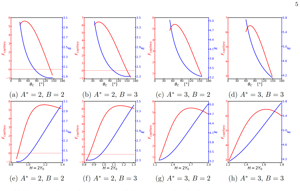
The load-bearing machinery is the static-friction law for contact lines, taken from the authors' earlier droplet analysis: the maximum static friction at a critical angle is proportional to $\sin\theta_c$ with one coefficient $\mu_s$. This law turns the modified Young's equations (the horizontal force balances at the pinned contact points) into two independent expressions for $\mu_s$; since $\mu_s$ is unique for a solid-liquid pair, equating them produces the Young-angle identity and then the hysteresis-width formula. The companion experimental machinery is the capillary force expression $F_{\rm capillary} = 2\sin\theta_u + 2BY_0 + (\cos\theta_u+\cos\theta_d)/Y_0$, with the no-gravity reduction $F_{\rm capillary} = 2(\sin\theta_C + \cos\theta_C/Y_0)$, together with the area constraint and the height-contact-angle relation (Eq. (B1)) that let contact angles be inferred from force and separation instead of optics. Finally, the energy-force relation $F = -\partial E_{\rm total}/\partial H$ with $\partial^2 E/\partial Y_0^2 > 0$ supplies the spring-like stability and effective spring constants.
What would settle it
Run repeated push-down and pull-up cycles on a single capillary bridge of known liquid and solid while recording capillary force and plate separation; extract the advancing and receding angles and compute $\mu_s$ from Eq. (12) separately for the two directions. If the two values disagree by more than experimental error, or if the Young's angle from Eq. (10) contradicts an independent determination obtained by a different method (for example, the value approached as hysteresis width goes to zero on the same surface), the friction law and the proposed derivation fail.
Extended reading notes
Core claim
The central claim is that contact-line pinning is static friction with a single coefficient per solid-liquid pair, and that this friction can be extracted from capillary-bridge force measurements. At each contact point the horizontal force balance gives modified Young's equations $\kappa_u = \gamma(\cos\theta_u-\cos\theta_Y)$ and $\kappa_d = \gamma(\cos\theta_Y-\cos\theta_d)$; when the contact line is about to move, the maximum friction is written in terms of the critical angles, giving $\mu_s = (\cos\theta_Y-\cos\theta_a)/\sin\theta_a$ on the advancing side and $\mu_s = (\cos\theta_r-\cos\theta_Y)/\sin\theta_r$ on the receding side. Equating the two expressions yields the Young-angle formula, and substituting it back gives $\mu_s = \tan((\theta_a-\theta_r)/2)$, so the hysteresis width alone fixes the friction coefficient. The experimental content is that $\theta_a$ and $\theta_r$ need not be measured optically: measuring capillary force (Eq. (6)) and plate separation, with the area constraint (Eq. (A3)), determines the critical angles, and in zero gravity the contact angle follows from the separation alone. The paper also derives exact solutions to the Young-Laplace equation for the bridge profiles, shows the capillary force is the negative derivative of the energy with respect to height, and uses the positive second derivative to establish spring-like stability.
Load-bearing premise
The whole method rests on the assumption, carried over from the authors' earlier droplet paper, that the maximum static friction at a contact line grows with the sine of the critical contact angle and is described by one coefficient shared by both moving directions.
Editorial extensions
If this is right
- For a given solid-liquid pair, the Young's angle can be obtained from capillary force and plate-separation measurements alone, without optical contact-angle readings.
- In the absence of gravity the contact angle is determined by the plate separation via Eq. (B1), so the experimental protocol simplifies to measuring one length and one force.
- The widely used estimates $\theta_Y = \cos^{-1}[(\cos\theta_a+\cos\theta_r)/2]$ and $\theta_Y \approx (\theta_a+\theta_r)/2$ hold only when hysteresis is small; the paper's identity replaces them in general.
- The bridge is a stable spring with linear and quadratic constants $k_1 = -2\sin\theta_{\rm eq}\tan\theta_{\rm eq}$ and $k_2 = -2\sin\theta_{\rm eq}\tan^2\theta_{\rm eq}$ in zero gravity, so effective stiffness is predictable from the equilibrium contact angle.
- Because pinch-off can occur before a contact line reaches a critical angle for some areas and Bond numbers, the proposed protocol must choose parameter ranges where contact-line motion precedes pinch-off.
Reading between the lines
- A testable extension the paper does not spell out: repeated push-down and pull-up cycles on one bridge provide two independent estimates of $\mu_s$ via Eq. (12); agreement would support the single-coefficient friction law, and disagreement would localize where it fails.
- The identity $\mu_s = \tan((\theta_a-\theta_r)/2)$ implies that for a fixed hysteresis width the friction coefficient is independent of the absolute values of the contact angles; one could test this by comparing surfaces engineered to share $\theta_a-\theta_r$ while differing in $\theta_a$ and $\theta_r$.
- Because the bridge is a stable spring around equilibrium, small oscillations of the upper plate could extract the spring constants and thereby infer contact angles and friction dynamically, a route the paper leaves for future work.
- The force-separation protocol should transfer to axisymmetric and vertical bridges, where the competition between pinch-off and critical-angle motion would need to be characterized before routine use.
Editorial analysis
A structured set of objections, weighed in public.
Referee Report
Summary. The paper proposes a method to determine the static friction coefficient and the Young's angle for two-dimensional horizontal capillary bridges by measuring only the capillary force and the plate separation, avoiding direct contact-angle measurement. The authors derive exact solutions to the Young-Laplace equation for two-dimensional bridges with and without gravity, establish a spring-like relation between capillary force and energy, and derive formulas μs = tan((θa−θr)/2) and θY = cos^{−1}[sin(θa+θr)/(sinθa+sinθr)] from the assumption that a single static friction coefficient governs both advancing and receding contact-line motion. The appendices contain detailed energy-minimization and integration steps.
Significance. If the underlying constitutive assumption is valid, the proposed method would provide a practical experimental route to the Young's angle and a quantitative measure of contact-line friction, and the exact bridge profiles and spring relation are useful theoretical contributions. The appendices present detailed, checkable derivations, and the paper correctly identifies that direct contact-angle measurement is difficult. However, the central claim that the Young's angle can be determined rests entirely on an untested friction law imported from the authors' prior preprint, so the significance is conditional on that law.
major comments (3)
- [Section III, Eq. (8)] The derivation of Eq. (10) and Eq. (12) follows by equating the two expressions for μs in Eq. (8). This equating presumes that the maximum static friction at the advancing and receding contact lines is given by γ μs sinθa and γ μs sinθr with a single coefficient μs. This constitutive law is imported from reference [9] and is not tested or independently justified in the present manuscript. No experimental force–gap data, no simulation, and no literature comparison are provided that would support the sinθ scaling or the equality of μs for advancing and receding motion. Since this assumption is the load-bearing element of the proposed method, the claim that the Young's angle 'can be determined' is not established. The authors should either provide direct evidence for Eq. (8) or explicitly frame the results as consequences of that model, with a discussion of how violations (e.g., μs,a ≠ μs,r) would affect the inferred θY.
- [Section III and Eqs. (A3) and (6)] The proposed experimental protocol requires deducing the critical angles θa and θr from measured capillary force and plate separation. The manuscript does not specify how the onset of depinning is identified in the F–H curve—whether it appears as a slope discontinuity, a force plateau, or a jump—nor does it discuss the stability of the pinned state before the critical angle is reached. This information is essential for the practical implementation of the method and for verifying that the measured angles indeed correspond to the advancing/receding critical angles used in Eq. (8).
- [Section III, Eq. (10)] The paper contrasts Eq. (10) with the traditional formulas in Eq. (11) and concludes that the traditional relations are valid only for small hysteresis. However, this comparison is made under the same unvalidated friction law; without an independent determination of θY, the numerical closeness to Adam and Jessop's value is not evidence for the correctness of Eq. (10). The authors should temper the conclusion or provide a separate argument that does not rely on the very assumption being tested.
minor comments (5)
- [Eq. (3)] The function f(Y) is used before its definition is clearly stated; please define all symbols in a single notation table or at first use.
- [Figures 4 and 5] The captions for Figs. 4 and 5 do not identify which line corresponds to which branch of Eq. (8); please add explicit labels or a legend.
- [Section II, after Eq. (5)] The statement that 'the maximum static friction takes different values' is confusing because Eq. (5) defines κu and κd as constraint forces, not maximum values; please clarify the connection between κu, κd and the maximum static friction used in Eq. (8).
- [Reference [9]] Reference [9] is cited as an arXiv preprint; if it has been published or accepted, please update the citation.
- [Appendix B] The piecewise definition of Y0,max and the conditions for pinch-off would be clearer if the physical meaning of the two cases (no pinch-off vs. pinch-off) were explained in the main text.
Circularity Check
The proposed determinations of θY and μs are algebraic rearrangements of the self-cited friction law Eq. (8); the central result reduces by construction to an ansatz imported from the authors' own preprint [9].
-
ansatz smuggled in via citation
[Section III, Eq. (8) through Eq. (10)]
"As we have argued in our previous work on two-dimensional droplets [9], the coefficient of static friction is defined from the critical angles (advancing angle θa and receding angle θr) as follows: µs = (cos θY − cos θa)/sin θa (θa = θd, θ u > θr); (cos θr − cos θY)/sin θr (θr = θu, θ d < θa). (8) Since the coefficient of static friction should be unique for a given solid-liquid interface, the Young’s contact angle can be determined by equating the two expressions in Eq.(8): θY = cos−1( sin(θa + θr)/(sinθa + sinθr) ). (10)"
Eq. (8) is the load-bearing constitutive law, taken from the authors' own preprint [9], and it already contains θY. Eq. (10) is obtained simply by equating the two lines of Eq. (8) and solving for θY; no independent measurement or derivation of the sinθ scaling or of equal μs for advancing and receding is provided. The only cited support for this law is the authors' unreviewed preprint. Thus the claimed determination of the Young angle is, by construction, a consistency condition of the assumed friction model rather than a result with independent empirical content.
-
self definitional
[Section III, Eqs. (10)-(12)]
"Substituting Eq.(10) back into Eq.(8) or Eq.(9), the two expressions for the coefficient of static friction µs is merged into a single formula µs = tan( (θa − θr)/2 ). (12) Hence µs can be determined solely from the critical contact angles without knowing the Young’s angle θY."
Eq. (12) is a rewrite of the same defining relation: μs was defined in Eq. (8) in terms of θY and θc, and Eq. (10) was itself derived from Eq. (8). Presenting the resulting expression as a determination that does not require knowing θY obscures that the relation was assumed at the outset. Neither Eq. (10) nor Eq. (12) adds information beyond the self-cited friction ansatz.
full rationale
The paper's exact Young-Laplace solutions, spring-constant relations, and pinch-off analysis are independent equilibrium calculations and are not circular. The circularity is localized in the headline result: the formulas for θY and μs are derived by equating the two branches of Eq. (8), a constitutive law imported from reference [9], the authors' own preprint, which already contains θY. No experimental data, simulation, or independent literature test validates the sinθ friction scaling or the single-coefficient assumption, so the central 'determination' of the Young angle reduces to a self-cited ansatz. The score is 6 because the prediction is a partial reduction by construction, even though the bridge geometry and force-height relations themselves are not circular.
Assumptions & free parameters
assumptions (3)
- domain assumption Contact points are perfectly pinned during quasi-static displacement, with x(0)=x(2y0)=x0, and static friction provides the constraint forces κu and κd.
- ad hoc to paper The maximum static friction force at each contact point is proportional to sinθ of the critical contact angle, with the same coefficient μs for advancing and receding, giving Eq. (8).
- standard math Young's equation holds locally at contact points, with Δγ = γ cosθY and additional static friction terms, as expressed in Eq. (A1).
Cite this review
Pith. "Pith review of Determination of the Young's angle using static friction in capillary bridges." pith.science (2026). https://pith.science/paper/QU76LWGB
@misc{pith2026241115021,
  author       = {Pith},
  title        = {Pith review of: Determination of the Young's angle using static friction in capillary bridges},
  year         = {2026},
  howpublished = {\url{https://pith.science/paper/QU76LWGB}},
  note         = {Machine review of arXiv:2411.15021}
}
read the original abstract
Recently contact angle hysteresis in two-dimensional droplets lying on a solid surface has been studied extensively in terms of static friction due to pinning forces at contact points. Here we propose a method to determine the coefficient of static friction using two-dimensional horizontal capillary bridges. This method requires only the measurement of capillary force and separation of plates, dispensing with the need for direct measurement of critical contact angles which is notoriously difficult. Based on this determination of friction coefficient, it is possible to determine the Young's angle from its relation to critical contact angles (advancing or receding). The Young's angle determined with our method is different either from the value estimated by Adam and Jessop a hundred years ago or the value argued by Drelich recently, though it is much closer to Adam and Jessop's numerically. The relation between energy and capillary force shows a capillary bridge behaves like a spring. Solving the Young-Laplace's equation, we can also locate the precise positions of neck or bulge and identify the exact moment when a pinch-off occurs.
Figures


Figures from the paper (4 more)


Reference graph
Works this paper leans on
-
[9]
J. W. Drelich, L. Boinovich, E. Chibowski, C. D. Volpe, L. Ho lysz, A. Marmur, and S. Siboni, Contact angles: history of over 200 years of open questions, Surf. Innov. 8, 3 (2020)
work page 2020
-
[1]
In a capillary bridge without gravity, the system has the up-down symmetry about y = y0, so the upper and down contact angles are the same (i.e
And the Bond number is defined as B ≡ ρgx2 0/γ where ρ and g are the density of liquid and the acceleration of gravity, respectively. In a capillary bridge without gravity, the system has the up-down symmetry about y = y0, so the upper and down contact angles are the same (i.e. θu = θd ≡ θC). The equilibrium contact angle ( θeq) and the Young’s angle ( θY...
-
[2]
The circular profile, XC (Y ), is obtained by integrating the above Young-Laplace’s equation [82]
Without gravity ( B = 0) When B = 0, Eq.(A2) and Eq.(A4) reduce to − d dY X ′ C (Y )q 1 + {X ′ C (Y )}2 − β∗ C = 0, β ∗ C = − cos θC Y0 . The circular profile, XC (Y ), is obtained by integrating the above Young-Laplace’s equation [82]. XC (Y ) = 1 + Y0 tan θC − 1 cos θC q Y 2 0 − (Y − Y0)2 cos2 θC It is part of a circle with radius |Y0/ cos θC| c...
-
[3]
With gravity ( B >0) Substituting Eq.(A4) into Eq.(A2) and integrating both sides, we get X ′ (Y ) = f (Y )q 1 − {f (Y )}2 (B3) 10 FIG. 6. The shape of two-dimensional horizontal capillary bridges when A∗ = 4 ( θC,pinch ∼= 54.52◦, θC,min ∼= 49.85◦). The exact solutions are given in Appendix B. Blue, green, and red bridges correspond to Y0,−, Y0 = A∗/2, an...
-
[4]
Without gravity ( B = 0) When there is no gravity, the point at Y = Y0,± represents either a neck or a bulge ( X ′ C (Y0,±) = 0). Depending on the value of XC,± ≡ XC (Y0,±) compared to the position of the contact point ( X = 1) (or equivalently, depending on the sign of X ′′ C (Y0,±)), we can divide the general shapes of the bridges into three separate ca...
-
[5]
So, we have Y1,± = ¯Y ± r ¯Y 2 + 2 B cos θd (C1) where ¯Y is defined in Eq.(B4)
With gravity ( B >0) The positions of a neck or a bulge ( X1 ≡ X (Y1) , Y1) are defined by the relation X ′ (Y1) = 0. So, we have Y1,± = ¯Y ± r ¯Y 2 + 2 B cos θd (C1) where ¯Y is defined in Eq.(B4). A neck ( X1 < 1) or a bulge ( X1 > 1) can appear only when its position Y1 is in the interval 0 ≤ Y1,± ≤ 2Y0. When there is gravity, the rectangular solution ...
-
[6]
N. K. Adam and G. Jessop, Ccl.—angles of contact and polarity of solid surfaces, J. Chem. Soc. Trans. 127, 1863 (1925)
1925
-
[7]
N. K. Adam, The Physics and Chemistry of Surfaces, 3rd(Oxford University Press, 1941). 13
1941
Show all 88 references
-
[8]
R. J. Good, A thermodynamic derivation of wenzel’s modification of young’s equation for contact angles; together with a theory of hysteresis, J. Am. Chem. Soc. 74, 20, 5041 (1952)
1952
-
[10]
H.-J. Butt, J. Liu, K. Koynov, B. Straub, C. Hinduja, I. Roismann, R. Berger, X. Li, D. Vollmer, W. Steffen, and M. Kappl, Contact angle hysteresis, Curr. Opin. Colloid Interface Sci. 59, 101574 (2022)
2022
-
[11]
N. Gao, F. Geyer, D. W. Pilat, S. Wooh, D. Vollmer, H.-J. Butt, and R. Berger, How drops start sliding over solid surfaces, Nat. Phys. 14, 191 (2018)
2018
-
[12]
McHale, N
G. McHale, N. Gao, G. G. Wells, H. Barrio-Zhang, and R. Ledesma-Aguilar, Friction coefficients for droplets on solids: The liquid-solid amontons’ laws, Langmuir 38, 4425 (2022)
2022
-
[13]
Zhang, W
J. Zhang, W. Ding, and U. Hampel, How droplets pin on solid surfaces, J. Colloid Interface Sci. 640, 15, 940 (2023)
2023
-
[14]
Yang and J
J.-I. Yang and J. Hong, Contact angle hysteresis and static friction for two-dimensional droplets, arXiv:2408.04240
-
[15]
Lv and S
See, as an exception, a recent paper by Lv and Shi in which they devised an experiment for a two-dimensional droplet system: C. Lv and S. Shi, Wetting states of two-dimensional drops under gravity, Phys. Rev. E 98, 042802 (2018)
2018
-
[16]
Drelich and J
J. Drelich and J. D. Miller, The effect of solid surface heterogeneity and roughness on the contact angle/drop (bubble) size relationship, J. Colloid Interface Sci. 164, 252 (1994)
1994
-
[17]
C. W. Extrand and Y. Kumagai, Liquid drops on an inclined plane: The relation between contact angles, drop shape, and retentive force, J. Colloid Interface Sci. 170, 515 (1995)
1995
-
[18]
Krasovitski and A
B. Krasovitski and A. Marmur, Drops down the hill: Theoretical study of limiting contact angles and the hysteresis range on a tilted plate, Langmuir 21, 9, 3881 (2005)
2005
-
[19]
Pozzato, S
A. Pozzato, S. D. Zilio, G. Fois, D. Vendramin, G. Mistura, M. Belotti, Y. Chen, and M. Natali, Superhydrophobic surfaces fabricated by nanoimprint lithography, Microelectron. Eng. 83, 884 (2006)
2006
-
[20]
Pierce, F
E. Pierce, F. J. Carmona, and A. Amirfazli, Understanding of sliding and contact angle results in tilted plate experiments, Colloids Surf. A: Physicochem. Eng. Asp. 323, 73 (2008)
2008
-
[21]
B. J. Ryan and K. M. Poduska, Roughness effects on contact angle measurements, Am. J. Phys. 76, 1074 (2008)
2008
-
[22]
Kalantarian, R
A. Kalantarian, R. David, and A. W. Neumann, Methodology for high accuracy contact angle measurement, Langmuir 25, 14146 (2009)
2009
-
[23]
J. W. Krumpfera and T. J. McCarthy, Contact angle hysteresis: a different view and a trivial recipe for low hysteresis hydrophobic surfaces, Faraday Discuss 146, 103 (2010)
2010
-
[24]
H. Xu, Z. Yuan, J. Lee, H. Matsuura, and F. Tsukihashi, Contour evolution and sliding behavior of molten sn-ag-cu on tilting cu and al2o3 substrates, Colloids Surf. A: Physicochem. Eng. Asp. 359, 1 (2010)
2010
-
[25]
M. A. Rodriguez-Valverde, F. J. M. Ruiz-Cabello, and M. A. Cabrerizo-Vilchez, A new method for evaluating the most- stable contact angle using mechanical vibration, Soft Matter 7, 53 (2010)
2010
-
[26]
F. J. M. Ruiz-Cabello, M. A. Rodriguez-Valverde, and M. Cabrerizo-Vilchez, A new method for evaluating the most stable contact angle using tilting plate experiments, Soft Matter 7, 10457 (2011)
2011
-
[27]
F. J. M. Ruiz-Cabello, M. A. Rodriguez-Valverde, and M. A. Cabrerizo-Vilchez, Contact angle hysteresis on polymer surfaces: An experimental study, J. Adhes. Sci. Technol. 25, 2039 (2011)
2011
-
[28]
Srinivasan, G
S. Srinivasan, G. H. McKinley, and R. E. Cohen, Assessing the accuracy of contact angle measurements for sessile drops on liquid-repellent surfaces, Langmuir 27, 13582 (2011)
2011
-
[29]
Behroozi, Determination of contact angle from the maximum height of enlarged drops on solid surfaces, Am
F. Behroozi, Determination of contact angle from the maximum height of enlarged drops on solid surfaces, Am. J. Phys. 80, 284 (2012)
2012
-
[30]
A. V. Prydatko, L. A. Belyaeva, L. Jiang, L. M. C. Lima, and G. F. Schneider, Contact angle measurement of free-standing square-millimeter single-layer graphene, Nat. Commun. 9, 4185 (2018)
2018
-
[31]
H. Chen, J. L. Muros-Cobos, and A. Amirfazli, Contact angle measurement with a smartphone, Rev. Sci. Instrum. 89, 035117 (2018)
2018
-
[32]
P. D. Ravazzoli, I. Cuellar, A. G. Gonz´ alez, and J. A. Diez, Contact-angle-hysteresis effects on a drop sitting on an incline plane, Phys. Rev. E 99, 043105 (2019)
2019
-
[33]
Zhang, J
H. Zhang, J. Gottberg, and S. Ryu, Contact angle measurement using a hele-shaw cell: A proof-of-concept study, Results Eng. 11, 100278 (2021)
2021
-
[34]
Beitollahpoor, M
M. Beitollahpoor, M. Farzam, and N. S. Pesika, Determination of the sliding angle of water drops on surfaces from friction force measurements, Langmuir 38, 6, 2132 (2022)
2022
-
[35]
Klauser, F
W. Klauser, F. T. von Kleist-Retzow, and S. Fatikow, Line tension and drop size dependence of contact angle at the nanoscale, Nanomaterials 12, 369 (2022)
2022
-
[36]
M. J. Wood, D. G. K. Aboud, G. Zeppetelli, M. B. Asadi, and A.-M. Kietzig, Introducing a graphical user interface for dynamic contact angle determination, Phys. Fluids 35, 072010 (2023)
2023
-
[37]
Shumaly, F
S. Shumaly, F. Darvish, X. Li, A. Saal, C. Hinduja, W. Steffen, O. Kukharenko, H.-J. Butt, and R. Berger, Deep learning to analyze sliding drops, Langmuir 39, 1111 (2023)
2023
-
[38]
O. M. Johnson and F. Mangolini, Effect of camera parallax angle on the accuracy of static contact angle measurements, Langmuir 40, 10, 5090 (2024)
2024
-
[39]
T. Chen, L. Li, J. Guan, X. Shang, Z. Yang, L. Gu, R. Xu, and J. Chen, Reliable determination of contact angle from the liquid fence, Langmuir 40, 24, 12459 (2024)
2024
-
[40]
F. J. M. Ruiz-Cabello, M. A. Rodriguez-Valverde, and M. A. Cabrerizo-Vilchez, Equilibrium contact angle or the most- stable contact angle?, Adv. Colloid Interface Sci. 206, 320 (2014). 14
2014
-
[41]
J. W. Drelich, Contact angles: From past mistakes to new developments through liquid-solid adhesion measurements, Adv. Colloid Interface Sci. 267, 1 (2019)
2019
-
[42]
Drelich, No accessguidelines to measurements of reproducible contact angles using a sessile-drop technique, Surf
J. Drelich, No accessguidelines to measurements of reproducible contact angles using a sessile-drop technique, Surf. Innov. 1, 248 (2013)
2013
-
[43]
Huang and I
X. Huang and I. Gates, Apparent contact angle around the periphery of a liquid drop on roughened surfaces, Sci. Rep. 10, 8220 (2020)
2020
-
[44]
von Kleist-Retzow, W
F. von Kleist-Retzow, W. Klauser, S. Zimmermann, and S. Fatikow, Assessing micro- and nanoscale adhesion via liquid metal-based contact angle measurements in vacuum, J. Mater. Sci. 55, 4073 (2020)
2020
-
[45]
Marmur, The contact angle hysteresis puzzle, Colloids Interfaces 6, 39 (2022)
A. Marmur, The contact angle hysteresis puzzle, Colloids Interfaces 6, 39 (2022)
2022
-
[46]
Kadyrov, I
R. Kadyrov, I. Mukhamatdinov, and E. Statsenko, Determination of sessile drop wetting angle based on µct without the direct angle measurement, Langmuir 39, 2966 (2023)
2023
-
[47]
C. D. Willett, M. J. Adams, S. A. Johnson, and J. P. K. Seville, Capillary bridges between two spherical bodies, Langmuir 16, 24, 9396 (2000)
2000
-
[48]
Y. I. Rabinovich, M. S. Esayanur, and B. M. Moudgil, Capillary forces between two spheres with a fixed volume liquid bridge: Theory and experiment, Langmuir 21, 24, 10992 (2005)
2005
-
[49]
Cheneler, M
D. Cheneler, M. C. Ward, M. J. Adams, and Z. Zhang, Measurement of dynamic properties of small volumes of fluid using mems, Sensors and Actuators B: Chemical 130, 2, 701 (2008)
2008
-
[50]
E. J. D. Souza, L. Gao, T. J. McCarthy, E. Arzt, and A. J. Crosby, Effect of contact angle hysteresis on the measurement of capillary forces, Langmuir 24, 4, 1391 (2008)
2008
-
[51]
E. J. D. Souza, M. Brinkmann, C. Mohrdieck, A. Crosby, and E. Arzt, Capillary forces between chemically different substrates, Langmuir 24, 18, 10161 (2008)
2008
-
[52]
Nagy, Contact angle determination on hydrophilic and superhydrophilic surfaces by using r-θ-type capillary bridges, Langmuir 35, 5202 (2019)
N. Nagy, Contact angle determination on hydrophilic and superhydrophilic surfaces by using r-θ-type capillary bridges, Langmuir 35, 5202 (2019)
2019
-
[53]
Nagy, Capillary bridges on hydrophobic surfaces: Analytical contact angle determination, Langmuir 38, 19 , 6201 (2022)
N. Nagy, Capillary bridges on hydrophobic surfaces: Analytical contact angle determination, Langmuir 38, 19 , 6201 (2022)
2022
-
[54]
Daniel and X
D. Daniel and X. Q. Koh, Droplet detachment force and its relation to young-dupre adhesion, Soft Matter 19, 8434 (2023)
2023
-
[55]
Kralchevsky and K
P. Kralchevsky and K. Nagayama, Particles at Fluid Interfaces and Membranes: Attachment of Colloid Particles and Proteins to Interfaces and Formation of Two–Dimensional Arrays(Elsevier Science, 2001)
2001
-
[56]
D. W. Langbein, Capillary Surfaces: Shape - Stability - Dynamics, in Particular Under Weightlessness(Springer, 2002)
2002
-
[57]
Mastrangeli, The fluid joint: The soft spot of micro- and nanosystems, Adv
M. Mastrangeli, The fluid joint: The soft spot of micro- and nanosystems, Adv. Mater. 27, 29, 4254 (2015)
2015
-
[58]
M. A. Fortes, Axisymmetric liquid bridges between parallel plates, J. Colloid Interface Sci. 88, 2, 338 (1982)
1982
-
[59]
E. A. Boucher, M. J. B. Evans, and S. McGarry, Capillary phenomena: Xx. fluid bridges between horizontal solid plates in a gravitational field, J. Colloid Interface Sci. 89, 1, 154 (1982)
1982
-
[60]
Meseguer and A
J. Meseguer and A. Sanz, Numerical and experimental study of the dynamics of axisymmetric slender liquid bridges, J. Fluid Mech. 153, 83 (1985)
1985
-
[61]
I. D. Rive and I. Martinez, Floating liquid zones, Naturwissenschaften 73, 345 (1986)
1986
-
[62]
B. J. Lowry and P. H. Steen, Capillary surfaces: stability from families of equilibria with application to the liquid bridge, Proc. R. Soc. Lond. A 449, 411 (1995)
1995
-
[63]
Concus and R
P. Concus and R. Finn, Discontinuous behavior of liquids between parallel and tilted plates, Phys. Fluids 10, 39 (1998)
1998
-
[64]
Tadrist, L
L. Tadrist, L. Motte, O. Rahli, and L. Tadrist, Characterization of interface properties of fluids by evaporation of a capillary bridge, R. Soc. Open Sci. 6, 191608 (2019)
2019
-
[65]
H. N. G. Nguyen, O. Millet, C.-F. Zhao, and G. Gagneux, Theoretical and experimental study of capillary bridges between two parallel planes, Eur. J. Environ. Civ. Eng. 26(3), 1198 (2020)
2020
-
[66]
S. T. Chan, F. P. A. van Berlo, H. A. Faizi, A. Matsumoto, S. J. Haward, P. D. Anderson, and A. Q. Shen, Torsional fracture of viscoelastic liquid bridges, PNAS 118, 24, e2104790118 (2021)
2021
-
[67]
W. C. Carter, The forces and behavior of fluids constrained by solids, Acta Metall. 36, 8, 2283 (1988)
1988
-
[68]
L. R. Pratt, D. T. Gomez, A. Muralidharan, and N. Pesika, Shapes of nonsymmetric capillary bridges, J. Phys. Chem. B 125, 44, 12378 (2021)
2021
-
[69]
H. Chen, A. Amirfazli, and T. Tang, Modeling liquid bridge between surfaces with contact angle hysteresis, Langmuir 29, 10, 3310 (2013)
2013
-
[70]
Akbari and R
A. Akbari and R. J. Hill, Liquid-bridge stability and breakup on surfaces with contact-angle hysteresis, Soft Matter 12, 6868 (2016)
2016
-
[71]
M. S. Odunsi, J. F. Morris, and M. D. Shattuck, Hysteretic behavior of capillary bridges between flat plates, Langmuir 39, 37, 13149 (2023)
2023
-
[72]
J. W. van Honschoten, N. R. Tas, , and M. Elwenspoek, The profile of a capillary liquid bridge between solid surfaces, Am. J. Phys. 78, 277 (2010)
2010
-
[73]
H. N. G. Nguyen, O. Millet, and G. Gagneux, Liquid bridges between a sphere and a plane - classification of meniscus profiles for unknown capillary pressure, Math. Mech. Solids 24, 10, 3042 (2019)
2019
-
[74]
F. M. Orr, L. E. Scriven, and A. P. Rivas, Pendular rings between solids: meniscus properties and capillary force, J. Fluid Mech. 67, 4, 723 (1975)
1975
-
[75]
Reyssat, Capillary bridges between a plane and a cylindrical wall, J
E. Reyssat, Capillary bridges between a plane and a cylindrical wall, J. Fluid Mech. 773, R1 (2015)
2015
-
[76]
Cooray, H
H. Cooray, H. E. Huppert, and J. A. Neufeld, Maximal liquid bridges between horizontal cylinders, Proc. R. Soc. A. 472, 20160233 (2016). 15
2016
-
[77]
Lian and J
G. Lian and J. Seville, The capillary bridge between two spheres: New closed-form equations in a two century old problem, Adv. Colloid Interface Sci. 227, 53 (2016)
2016
-
[78]
N. P. Kruyt and O. Millet, An analytical theory for the capillary bridge force between spheres, J. Fluid Mech. 812, 129 (2017)
2017
-
[79]
G. Lian, C. Thornton, and M. J. Adams, A theoretical study of the liquid bridge forces between two rigid spherical bodies, J. Colloid Interface Sci. 161, 1, 138 (1993)
1993
-
[80]
D. J. Broesch and J. Frechette, From concave to convex: Capillary bridges in slit pore geometry, Langmuir 28, 44, 15548 (2012)
2012
-
[81]
P. I. C. Teixeira and M. A. C. Teixeira, The shape of two-dimensional liquid bridges, J. Phys. Condens. Matter 32, 1 (2019)
2019
-
[82]
Q. Wang, W. Chen, and J. Wu, Effect of capillary bridges on the interfacial adhesion of wearable electronics to epidermis, Int. J. Solids Struct. 174–175, 85 (2019)
2019
-
[83]
D. Pang, H. Cong, X. Li, H. Li, and X. Gao, Liquid-bridge flow between two slender plates: Formation and fluid mechanics, Chem. Eng. Res. Des. 170, 304 (2021)
2021
-
[84]
I. S. Gradshteyn, I. M. Ryzhik, and D. Zwillinger, Table of Integrals, Series, and Products, 8th(Academic Press, 2014)
2014
-
[85]
Kusumaatmaja and R
H. Kusumaatmaja and R. Lipowsky, Equilibrium morphologies and effective spring constants of capillary bridges, Langmuir 26, 24, 18734 (2010)
2010
-
[86]
Sariola, Analytical expressions for spring constants of capillary bridges and snap-in forces of hydrophobic surfaces, Langmuir 35, 22, 7129 (2019)
V. Sariola, Analytical expressions for spring constants of capillary bridges and snap-in forces of hydrophobic surfaces, Langmuir 35, 22, 7129 (2019)
2019
-
[87]
C. J. Delaunay, Sur la surface de r´ evolution dont la courbure moyenne est constante, J. Math. Pures Appl. 6, 309 (1841)
-
[88]
H. B. Dwight, Tables of Integrals and Other Mathematical Data, 4th(The Macmillan Company, 1961)
1961
Reviewed August 12, 2026 · model on record in the stance chip above.
Discussion (0). Continue with ORCID to comment.