REVIEW 5 major objections 7 minor 2 cited by
Enhanced Capture Point Control Using Thruster Dynamics and QP-Based Optimization for Harpy
T0 review · 5 major / 7 minor · reviewed 2026-08-12 · deepseek-v4-flash
Pith's one-line read Thruster force modifies the capture point law through effective gravity, and a QP controller using this law stabilizes Harpy's trotting in simulation.
desk verdict The core derivation is the standard LIP capture point with a modified gravity constant and the load-bearing θ_T = 0 assumption is unenforced, while the sim results are thin; still, the Harpy platform motivation is real and the paper deserves a serious referee with heavy revision. read the letter →
The pith
A machine-rendered reading of the paper's core claim, the machinery that carries it, and where it could break.
The reading
What carries the argument
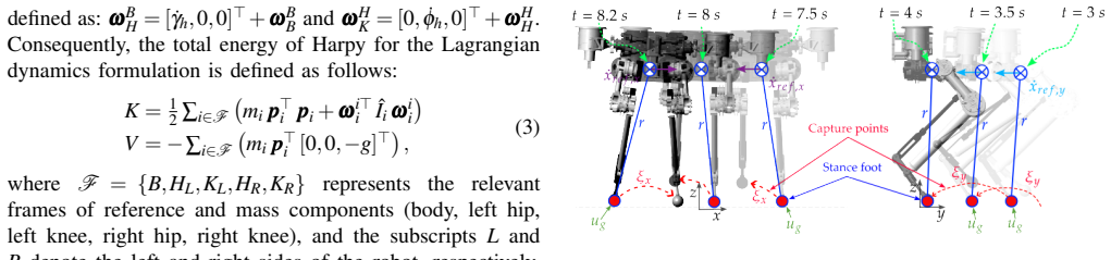
The central object is the capture point: the foot location at which the center of mass can come to rest over the support foot. The paper derives it from a variable-length inverted pendulum (VLIP) with a thruster force term, projected onto sagittal and frontal planes. With the thrust kept perpendicular to the ground, the system acts as a virtual-buoyancy model whose effective gravity is $g - |\mathbf{u}_{t,c}|/m$; the capture point is the stable-eigenvector condition of this model, giving Eq. (15). A dense quadratic program over the discretized capture-point dynamics then tracks a reference velocity with the thruster force as a parameter.
What would settle it
Run the trotting simulation with the body pitch free and compare the center-of-mass acceleration to Eq. (11) whenever the torso tilt is nonzero; a deviation matching $|\mathbf{u}_{t,c}|\sin\theta_T$ would show the capture-point law does not describe the real plant.
Extended reading notes
Core claim
The paper's claim is that the classical capture point remains valid for thruster-assisted walking once gravity is replaced by an effective gravity $g - |\mathbf{u}_{t,c}|/m$, where $|\mathbf{u}_{t,c}|$ is the combined thruster force about the center of mass and $m$ is the robot mass. Under the assumption that the thrust vector stays perpendicular to the ground ($\theta_T = 0$), the variable-length inverted pendulum equations reduce to $\ddot p_{B,x} = (g - |\mathbf{u}_{t,c}|/m) p_{B,x}/z_0$, whose stable eigenvector gives the foot placement rule $p_{B,x} = \dot p_{B,x}\sqrt{z_0/(g - |\mathbf{u}_{t,c}|/m)}$. The paper then embeds this modified capture point in a discrete-time state-space model and solves a dense QP at each step to track a desired reference velocity. The simulation evidence is that the QP controller stabilizes Harpy's body position toward the reference while keeping control efforts and joint torques within bounds.
Load-bearing premise
The whole derivation assumes the thruster force always points straight up, and the paper does not include a controller that keeps it that way; if the robot's torso tilts, the thrust adds a sideways push the model ignores.
Editorial extensions
If this is right
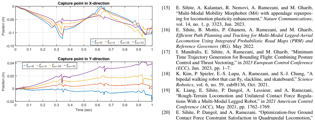
- Commanding a larger thruster force lowers effective gravity, so the same center-of-mass velocity requires a smaller sagittal capture point; the paper reports exactly this trend in its thrust-sweep figure.
- Without the QP loop the simulated robot drifts, while with it the body position settles near the reference, so the QP reference tracking is doing the stabilization, not the plant alone.
- The state-space model in Eq. (19) is linear with respect to the capture point once $\omega$ is fixed by thrust, so the same QP structure can be reused for different thrust levels by updating $\omega$.
- The paper's stated next step is to add ground reaction forces and thruster forces as QP decision variables; that extension is a natural corollary of treating them as parameters here.
Reading between the lines
- Because the modified law is just a substitution of effective gravity, the same substitution should transfer to related centroidal templates, such as divergent-component-of-motion or preview-control formulations, potentially shortening development of thruster-assisted walking controllers.
- The $\theta_T = 0$ assumption is not enforced by any torso controller, so on hardware the body pitch will rotate the fixed thrusters and inject an unmodeled horizontal force; a version with pitch regulation or gimbaled thrusters would test the model under realistic conditions.
- The reported scaling of capture point with thrust suggests a clean experimental check: hold velocity and height fixed, vary thrust, and see whether foot placement follows $\sqrt{z_0/(g - |\mathbf{u}_{t,c}|/m)}$; any systematic deviation would point to missing terms such as thrust misalignment or aero effects.
Editorial analysis
A structured set of objections, weighed in public.
Referee Report
Summary. The paper presents a capture-point-based controller with thruster forces for Harpy, a bipedal robot with torso-mounted thrusters. The authors derive a variable-length inverted pendulum model with thrust as virtual buoyancy, define a capture point that is used in a QP-based tracking controller, and evaluate the controller in a 10-second MATLAB Simscape trotting simulation. The claimed contribution is a new thruster-dependent capture point law and evidence that increasing thrust changes the capture point and stability.
Significance. If the central derivation were correct, the work would be a useful step toward combining legged and aerial locomotion on a single platform, and the constrained QP formulation with explicit thruster-force parameters is relevant to the community. The full Lagrangian model in Section II is a strength, as is the explicit treatment of thruster magnitude as a tunable parameter. However, the central capture-point derivation omits the CoM position term, the key assumption theta_T=0 is unenforced, and the main thrust-effect evidence is self-contradictory. The simulation validation is also too thin to support the claimed stability. The idea is defensible after major corrections.
major comments (5)
- [Section III-A, Eqs. (15)-(17)] The quantity called the capture point omits the current CoM position. The standard capture point is xi = x + xdot/omega, and the stable-manifold condition E=0 is x = -xdot/omega. Equation (15) instead states p_B,x = xdot_B,x * sqrt(z0/(g - |u_t,c|/m)), i.e., x = xdot/omega, which is the unstable eigenvector and has the wrong sign for a foot placement that stops the CoM. Consequently, Eq. (17) defines xi exclusively from velocity error, so the QP in Eq. (19) is not a capture-point controller. This must be corrected and the derivation repeated before the central claim can be assessed.
- [Section III-A, Eqs. (10)-(11)] The reduction from Eq. (10) to Eq. (11) requires theta_T = 0, but no controller enforces this condition. Because Harpy's thrusters are fixed to the torso, theta_T equals body pitch, and Fig. 5 shows pitch of about -6 degrees during the trot. With the reported |u_t,c| = 10 N and m = 4.5 kg, the neglected horizontal forcing is |u_t,c| sin(theta_T)/m, approximately 0.23 m/s^2, which is the same order as the retained stiffness term (g - |u_t,c|/m) x/z0 for x near 0.1 m. The internal model used by the QP therefore does not describe the plant, and the simulation outcome cannot be attributed to the thruster-adjusted capture point law.
- [Section IV, Fig. 9] The two panels of Fig. 9 present contradictory results: the top panel is described as showing that higher thrust reduces the capture point and increases stability, while the bottom panel shows higher thrust increasing capture point length, attributed to the fixed thruster position and falling motion. Since this figure is the primary evidence for the effect of thrust on the capture point, the contradiction must be resolved with a single consistent metric and explanation, or the claim should be removed from the conclusions.
- [Section III-B, Eqs. (17)-(24)] The state-space model in Eq. (19) is not reproducible as written: the state vector is two-dimensional while the matrix entries mix scalar and vector terms; the control input u is not defined before Eq. (24); and Eq. (18) is derived for constant xdot_ref even though xdot_ref appears as an input. With Kx = Ky = 1, xi is merely (xdot - xdot_ref)/omega, not a capture point. The QP formulation needs a complete, dimensionally consistent derivation.
- [Section IV] The simulation validation lacks quantitative support: no contact or friction model parameters, foot-slip measures, ground reaction force limits, or tracking error statistics are reported, and only a single 10-second trial is discussed. The claim of stable trotting needs well-defined metrics and at least a brief sensitivity analysis before it can be accepted.
minor comments (7)
- [Introduction] The statement that Harpy's height measures 600 cm is clearly a typo; for a 4.5 kg platform the intended value is likely 60 cm or 0.6 m.
- [Fig. 5] The axis labels in Fig. 5 contain corrupted characters (e.g., '? A 3', '!x', '!y', '!z'); the Euler-angle convention and angular-velocity labels should be cleaned up.
- [Notation throughout] The symbol u is overloaded: u_t for thruster force, u_j for joint torques, and u for QP control input; please use distinct symbols such as f_t, tau, and u_QP.
- [References] Reference [28] (Bickel et al., capture and modeling of soft tissue) does not appear relevant to capture-point control and should be replaced or removed.
- [Eq. (14)] The sign convention in Eq. (14) relative to Eq. (15) is not stated; the stable and unstable manifolds are distinguished only by the sign of xdot relative to x, so this ambiguity should be resolved in the text.
- [Fig. 9] The legend labels '9u=0' etc. should read 'u=0' (and similarly for the other values).
- [Section III-B] The word 'sinusodal' should be 'sinusoidal'.
Circularity Check
Thrust-vs-capture-point figure reduces to Eq. (15) by construction; the main QP stabilization result has independent Simscape support, so overall circularity is partial.
-
self definitional
[Section III-A, Eq. (15), and Section IV, Fig. 9]
"Assuming this exchange occurs instantaneously without energy loss, we can determine the foot placement based on the capture point, given by pB,x = ˙pB,x sqrt(z0/(g − |uuut,c|/m)) (15) ... Figure 9 demonstrates the effect of thrust force on the capture point. u is the combined thruster force generated by both the thrusters."
Equation (15) defines the capture point as CoM velocity times sqrt(z0/(g − |u_t,c|/m)). Therefore the dependence of the capture point on thruster magnitude is already built into its definition. When Figure 9 varies u (0, 5, 10, 15 N) and reports that the capture point changes in the direction predicted by the formula, it is evaluating the defining expression (or a controller variable computed from it) rather than testing it against independent data or a separate physical measurement. The monotone increase of capture-point magnitude with u follows directly from the factor sqrt(z0/(g − u/m)), so this 'result' is an illustration of the definition, not an empirical validation.
full rationale
The main stability claim — that the QP-CP controller keeps Harpy trotting in the full-body MATLAB Simscape model — is not circular: the Simscape plant is an independent, full-order simulation, and Figures 5, 6, 7, and 8 report closed-loop states, control efforts, torques, and position tracking from that plant. The QP forward model in Eq. (19) is indeed a rearrangement of the controller's own capture-point definition, but using an internal model inside a QP is standard model-based control design, not a prediction that is being validated. No load-bearing self-citation is present; the derivation from the LIP dynamics to Eq. (15) is algebraically self-contained. The one genuinely circular element is Figure 9, which presents the thrust-versus-capture-point trend as a demonstrated effect even though that trend is guaranteed by Eq. (15) by construction. Separately, the derivation assumes θ_T = 0 to pass from Eq. (10) to Eq. (11), and no torso-angle controller is presented to enforce it; this is a correctness and robustness concern, but it is not circularity. Overall circularity is therefore partial and localized, not one that forces the paper's central contribution.
Assumptions & free parameters
free parameters (4)
- Kx, Ky =
1, 1
- Q (state cost weights) =
diag(100, 100, 0.1, 0.1)
- R (control effort cost weights) =
diag(50, 55)
- Thruster force magnitude |u_t,c| =
0, 5, 10, 15 N (varied)
assumptions (6)
- domain assumption Legs and thrusters are massless; all mass concentrated at body and joint motors.
- domain assumption CoM height is constant (pB,z = z0, double-dot pB,z = 0) in the VLIP model.
- domain assumption Ground reaction force acts along the pendulum line from foot to CoM.
- ad hoc to paper Thruster force is kept perpendicular to the ground (theta_T = 0) during walking.
- domain assumption Swing leg exchange is instantaneous and lossless.
- domain assumption The QP prediction model in Eq. (19) is a valid predictor for the closed-loop plant.
Cite this review
Pith. "Pith review of Enhanced Capture Point Control Using Thruster Dynamics and QP-Based Optimization for Harpy." pith.science (2026). https://pith.science/paper/GG623POW
@misc{pith2026241117727,
  author       = {Pith},
  title        = {Pith review of: Enhanced Capture Point Control Using Thruster Dynamics and QP-Based Optimization for Harpy},
  year         = {2026},
  howpublished = {\url{https://pith.science/paper/GG623POW}},
  note         = {Machine review of arXiv:2411.17727}
}
read the original abstract
Our work aims to make significant strides in understanding unexplored locomotion control paradigms based on the integration of posture manipulation and thrust vectoring. These techniques are commonly seen in nature, such as Chukar birds using their wings to run on a nearly vertical wall. In this work, we developed a capture-point-based controller integrated with a quadratic programming (QP) solver which is used to create a thruster-assisted dynamic bipedal walking controller for our state-of-the-art Harpy platform. Harpy is a bipedal robot capable of legged-aerial locomotion using its legs and thrusters attached to its main frame. While capture point control based on centroidal models for bipedal systems has been extensively studied, the use of these thrusters in determining the capture point for a bipedal robot has not been extensively explored. The addition of these external thrust forces can lead to interesting interpretations of locomotion, such as virtual buoyancy studied in aquatic-legged locomotion. In this work, we derive a thruster-assisted bipedal walking with the capture point controller and implement it in simulation to study its performance.
Figures


Figures from the paper (6 more)


Forward citations
Cited by 2 Pith papers
-
Quadratic Programming-Based Posture Manipulation and Thrust-vectoring for Agile Dynamic Walking on Narrow Pathways
A centroidal-dynamics MPC controller with thrust-vectoring enables a simulated quadruped to walk on a narrow beam and reject lateral pushes.
-
Analysis of Harpy's Constrained Trotting and Jumping Maneuver
The provided manuscript text does not contain the claimed analysis of the Harpy robot, making the abstract's conclusions unverifiable from this document.
Reference graph
Works this paper leans on
-
[1]
M. P. Murphy, A. Saunders, C. Moreira, A. A. Rizzi, and M. Raib- ert, “The LittleDog robot,” The International Journal of Robotics Research, vol. 30, no. 2, pp. 145–149, Feb. 2011
work page 2011
-
[2]
[Online]
Robots — Boston Dynamics . [Online]. Available: https://www. bostondynamics.com/robots (visited on 05/27/2020)
2020
-
[3]
Boston Dynamics, All New Atlas — Boston Dynamics , Apr. 2024. [Online]. Available: https://www.youtube.com/watch?v= 29ECwExc-_M (visited on 07/08/2024)
work page 2024
-
[4]
Boston Dynamics, Meet Sparkles — Boston Dynamics , Apr. 2024. [Online]. Available: https://www.youtube.com/watch?v= MG4PPkCyJig (visited on 07/08/2024)
work page 2024
-
[5]
H.-W. Park, A. Ramezani, and J. W. Grizzle, “A Finite-State Machine for Accommodating Unexpected Large Ground-Height Variations in Bipedal Robot Walking,” IEEE Transactions on Robotics , vol. 29, no. 2, pp. 331–345, Apr. 2013
work page 2013
-
[6]
Preliminary walking experiments with underactuated 3D bipedal robot MARLO,
B. G. Buss, A. Ramezani, K. Akbari Hamed, B. A. Griffin, K. S. Galloway, and J. W. Grizzle, “Preliminary walking experiments with underactuated 3D bipedal robot MARLO,” in 2014 IEEE/RSJ Inter- national Conference on Intelligent Robots and Systems , Chicago, IL, USA: IEEE, Sep. 2014, pp. 2529–2536
work page 2014
-
[7]
Performance Analysis and Feedback Control of ATRIAS, A Three- Dimensional Bipedal Robot,
A. Ramezani, J. W. Hurst, K. Akbari Hamed, and J. W. Grizzle, “Performance Analysis and Feedback Control of ATRIAS, A Three- Dimensional Bipedal Robot,” Journal of Dynamic Systems, Measure- ment, and Control , vol. 136, no. 2, Mar. 2014
work page 2014
-
[8]
Progress on Controlling MARLO, an ATRIAS- series 3D Underactuated Bipedal Robot,
J. W. Grizzle, A. Ramezani, B. Buss, B. Griffin, K. A. Hamed, and K. S. Galloway, “Progress on Controlling MARLO, an ATRIAS- series 3D Underactuated Bipedal Robot,”
Show all 33 references
-
[9]
Fast Online Trajectory Optimization for the Bipedal Robot Cassie,
T. Apgar, P. Clary, K. Green, A. Fern, and J. Hurst, “Fast Online Trajectory Optimization for the Bipedal Robot Cassie,” in Robotics: Science and Systems XIV , Jun. 2018
2018
-
[10]
ASIMO and Humanoid Robot Research at Honda,
S. Shigemi, “ASIMO and Humanoid Robot Research at Honda,” in Humanoid Robotics: A Reference , Dordrecht: Springer Netherlands, 2019, pp. 55–90
2019
-
[11]
Biped walking pattern generation by using preview control of zero-moment point,
S. Kajita, F. Kanehiro, K. Kaneko, et al. , “Biped walking pattern generation by using preview control of zero-moment point,” in 2003 IEEE International Conference on Robotics and Automation (Cat. No.03CH37422), vol. 2, Sep. 2003, 1620–1626 vol.2
2003
-
[12]
DRC-hubo walking on rough terrains,
H. Wang, Y . F. Zheng, Y . Jun, and P. Oh, “DRC-hubo walking on rough terrains,” in 2014 IEEE International Conference on Technologies for Practical Robot Applications (TePRA) , Apr. 2014, pp. 1–6
2014
-
[13]
TALOS: A new humanoid research platform targeted for industrial applications,
O. Stasse, T. Flayols, R. Budhiraja, et al., “TALOS: A new humanoid research platform targeted for industrial applications,” in 2017 IEEE- RAS 17th International Conference on Humanoid Robotics (Hu- manoids), Nov. 2017, pp. 689–695
2017
-
[14]
Design of a Momentum- Based Control Framework and Application to the Humanoid Robot Atlas,
T. Koolen, S. Bertrand, G. Thomas, et al., “Design of a Momentum- Based Control Framework and Application to the Humanoid Robot Atlas,” International Journal of Humanoid Robotics , vol. 13, no. 01, p. 1 650 007, Mar. 2016
2016
-
[15]
Multi-Modal Mobility Morphobot (M4) with appendage repurpos- ing for locomotion plasticity enhancement,
E. Sihite, A. Kalantari, R. Nemovi, A. Ramezani, and M. Gharib, “Multi-Modal Mobility Morphobot (M4) with appendage repurpos- ing for locomotion plasticity enhancement,” Nature Communications, vol. 14, no. 1, p. 3323, Jun. 2023
2023
-
[16]
Sihite, B
E. Sihite, B. Mottis, P. Ghanem, A. Ramezani, and M. Gharib, Efficient Path Planning and Tracking for Multi-Modal Legged-Aerial Locomotion Using Integrated Probabilistic Road Maps (PRM) and Reference Governors (RG) . May 2022
2022
-
[17]
Minimum Time Trajectory Generation for Bounding Flight: Combining Posture Control and Thrust Vectoring,
I. Mandralis, E. Sihite, A. Ramezani, and M. Gharib, “Minimum Time Trajectory Generation for Bounding Flight: Combining Posture Control and Thrust Vectoring,” in2023 European Control Conference (ECC), Jun. 2023, pp. 1–7
2023
-
[18]
A bipedal walking robot that can fly, slackline, and skateboard,
K. Kim, P. Spieler, E.-S. Lupu, A. Ramezani, and S.-J. Chung, “A bipedal walking robot that can fly, slackline, and skateboard,”Science Robotics, vol. 6, no. 59, eabf8136, Oct. 2021
2021
-
[19]
Rough-Terrain Locomotion and Unilateral Contact Force Regula- tions With a Multi-Modal Legged Robot,
K. Liang, E. Sihite, P. Dangol, A. Lessieur, and A. Ramezani, “Rough-Terrain Locomotion and Unilateral Contact Force Regula- tions With a Multi-Modal Legged Robot,” in 2021 American Control Conference (ACC), May 2021, pp. 1762–1769
2021
-
[20]
Optimization-free Ground Contact Force Constraint Satisfaction in Quadrupedal Locomotion,
E. Sihite, P. Dangol, and A. Ramezani, “Optimization-free Ground Contact Force Constraint Satisfaction in Quadrupedal Locomotion,” in 2021 60th IEEE Conference on Decision and Control (CDC), Dec. 2021, pp. 713–719
2021
-
[21]
Wing-Assisted Incline Running and the Evolution of Flight,
K. P. Dial, “Wing-Assisted Incline Running and the Evolution of Flight,” Science, vol. 299, no. 5605, pp. 402–404, Jan. 2003
2003
-
[22]
Aerodynamics of wing-assisted incline running in birds,
B. W. Tobalske and K. P. Dial, “Aerodynamics of wing-assisted incline running in birds,” Journal of Experimental Biology, vol. 210, no. 10, pp. 1742–1751, May 2007
2007
-
[23]
Dynamic multimodal locomotion: A quick overview of hardware and control.,
S. Pitroda, “Dynamic multimodal locomotion: A quick overview of hardware and control.,” 2023
2023
-
[24]
Feedback design for Harpy: A test bed to inspect thruster-assisted legged locomotion,
P. Dangol and A. Ramezani, “Feedback design for Harpy: A test bed to inspect thruster-assisted legged locomotion,” in Unmanned Systems Technology XXII, vol. 11425, SPIE, May 2020, pp. 49–55
2020
-
[25]
Control of Thruster-Assisted, Bipedal Legged Locomotion of the Harpy Robot,
P. Dangol, E. Sihite, and A. Ramezani, “Control of Thruster-Assisted, Bipedal Legged Locomotion of the Harpy Robot,” Frontiers in Robotics and AI , vol. 8, Dec. 2021
2021
-
[26]
Generalizations of the capture point to nonlinear center of mass paths and uneven terrain,
O. E. Ramos and K. Hauser, “Generalizations of the capture point to nonlinear center of mass paths and uneven terrain,” in 2015 IEEE-RAS 15th International Conference on Humanoid Robots (Hu- manoids), Seoul, South Korea: IEEE, Nov. 2015, pp. 851–858
2015
-
[27]
Capture Point-Based Controller Using Real-Time Zero Moment Point Manipulation for Stable Bipedal Walking in Human Environment,
Y .-D. Hong, “Capture Point-Based Controller Using Real-Time Zero Moment Point Manipulation for Stable Bipedal Walking in Human Environment,” Sensors, vol. 19, no. 15, p. 3407, Jan. 2019
2019
-
[28]
Capture and modeling of non-linear heterogeneous soft tissue,
B. Bickel, M. B ¨acher, M. A. Otaduy, W. Matusik, H. Pfister, and M. Gross, “Capture and modeling of non-linear heterogeneous soft tissue,” ACM Transactions on Graphics , vol. 28, no. 3, 89:1–89:9, Jul. 2009
2009
-
[29]
Extended Capture Point and Optimization- based Control for Quadrupedal Robot Walking on Dynamic Rigid Surfaces,
A. Iqbal and Y . Gu, “Extended Capture Point and Optimization- based Control for Quadrupedal Robot Walking on Dynamic Rigid Surfaces,” IFAC-PapersOnLine, vol. 54, pp. 72–77, Jan. 2021
2021
-
[30]
Stabilization of the Capture Point Dynamics for Bipedal Walking based on Model Predictive Control,
M. Krause, J. Englsberger, P.-B. Wieber, and C. Ott, “Stabilization of the Capture Point Dynamics for Bipedal Walking based on Model Predictive Control,” IFAC Proceedings Volumes, 10th IFAC Symposium on Robot Control, vol. 45, no. 22, pp. 165–171, Jan. 2012
2012
-
[31]
Capture Point: A Step toward Humanoid Push Recovery,
J. Pratt, J. Carff, S. Drakunov, and A. Goswami, “Capture Point: A Step toward Humanoid Push Recovery,” in 2006 6th IEEE- RAS International Conference on Humanoid Robots , University of Genova, Genova, Italy: IEEE, Dec. 2006, pp. 200–207
2006
-
[32]
Pitroda, A
S. Pitroda, A. Bondada, K. V . Krishnamurthy, et al. , Cap- ture Point Control in Thruster-Assisted Bipedal Locomotion , en, arXiv:2406.14799 [cs, eess], Jun. 2024. [Online]. Available: http: //arxiv.org/abs/2406.14799 (visited on 07/08/2024)
2024 arXiv
-
[33]
qpSWIFT: A Real-Time Sparse Quadratic Program Solver for Robotic Applications,
A. G. Pandala, Y . Ding, and H.-W. Park, “qpSWIFT: A Real-Time Sparse Quadratic Program Solver for Robotic Applications,” IEEE Robotics and Automation Letters , vol. 4, no. 4, pp. 3355–3362, Oct. 2019
2019
Reviewed August 12, 2026 · model on record in the stance chip above.
Discussion (0). Continue with ORCID to comment.