REVIEW 3 major objections 7 minor 24 references
Loop Shaping of Hybrid Motion Control with Contact Transition
T0 review · 3 major / 7 minor · reviewed 2026-08-12 · deepseek-v4-flash
Pith's one-line read Loop shaping of the disturbance sensitivity function $S(s)=1/(Z(s)s)$ lets a stiff displacement-feedback controller reconfigure on contact without any force measurement, as demonstrated on a 1-DOF actuator meeting a grape.
desk verdict A clean proof-of-concept for sensor-free contact-adaptive loop shaping, undermined by a hand-tuned threshold and missing switched-system analysis; worth reviewing, not worth taking as a guarantee. read the letter →
The pith
A machine-rendered reading of the paper's core claim, the machinery that carries it, and where it could break.
The reading
What carries the argument
The load-bearing identity is $S(s)=1/(Z(s)s)$, which ties the closed-loop disturbance sensitivity to the contact environment's impedance and follows from comparing the control stiffness definition, the impedance ratio, and the sensitivity transfer function. The design formulas that carry the argument are the stiff controller $C_s(s)=\omega_0^2/(G(s)s(s+2\omega_0))$ obtained from a critically damped reference model, and the reshaped viscous controller $C_v(s)=(\alpha s G(s)-1)/G(s)$, with a low-pass filter added for properness; the viscoelastic controller $C_{ve}$ adds a saturated proportional error term to $C_v$. The switching law is a threshold comparison $|u(t)|>U$ on the already-available control signal, supported by the disturbance-to-control transfer function which shows that an over-limit control value indicates an external force. Together these pieces make the contact transition detectable and executable with no force measurement.
What would settle it
Run the same no-contact reference trajectory with added Coulomb friction or increased measurement noise so that $|u(t)|$ exceeds $U=1.3$ at some instant; if the controller switches to the soft mode with no object present, the sensor-free contact detection is falsified. Equivalently, a contact that is so soft that $|u|$ never exceeds $U$ would not trigger the switch, and the tool would penetrate.
Extended reading notes
Core claim
The paper's central claim is that the disturbance sensitivity function $S(s)=x(s)/F(s)$ of a closed-loop motion system is the inverse of the control stiffness operator, so prescribing an environmental impedance $Z(s)$ is equivalent to prescribing $S(s)=1/(Z(s)s)$. From this identity, the author derives a stiff controller $C_s$ given by a critically damped reference model, and two reshaped controllers, a purely viscous $C_v$ and a viscoelastic $C_{ve}$, that realize the desired contact impedance. The hybrid scheme switches from $C_s$ to $C_v$ or $C_{ve}$ whenever the magnitude of the control signal exceeds a threshold $U$, justified through the disturbance-to-control transfer function $U(s)=u(s)/F(s)$. In the experimental case study, the stiff controller drives the tool into the grape, whereas the viscous controller produces a slightly repulsive response and the viscoelastic controller presses the grape with a bounded, saturated force while avoiding penetration.
Load-bearing premise
The load-bearing premise is that in contact-free motion the control signal stays below the chosen threshold $U$, so $|u(t)|>U$ uniquely indicates contact; the paper sets $U=1.3$ and shows one no-contact trajectory, but does not analyze how friction, measurement noise, or trajectory transients affect this margin.
Editorial extensions
If this is right
- Any position-controlled axis with a known nominal plant $G(s)$ of relative degree at most 2 can be extended with a safe contact mode by reshaping $S(s)$, without adding hardware.
- Contact detection reduces to a threshold test on the control signal, so the method runs on existing real-time controllers that already log $u(t)$.
- The two reshaped controllers give distinct behaviors — viscous repulsion or viscoelastic bounded-force pressing — so the same switching law can be tuned to different tasks by choosing $C_v$ or $C_{ve}$.
- Because the design is carried out in the frequency domain, the non-contact performance can still be analyzed with standard Bode and sensitivity tools.
- The experimental grape scenario suggests applicability to medical palpation and fragile-object handling, where penetration must be avoided without a dedicated force sensor.
Reading between the lines
- The threshold $U$ is the only ad hoc parameter in the method; a systematic margin analysis that includes Coulomb friction, measurement noise, and trajectory transients would make the switching decision provably robust.
- The identity $S(s)=1/(Z(s)s)$ invites generalization to nonlinear or Hunt-Crossley contact models by shaping $S(s)$ accordingly, although the paper only treats linear viscous and viscoelastic environments.
- Near the threshold, the switching law could chatter if the contact force hovers around $U$; adding hysteresis or a dwell time is an obvious practical hardening.
- After switching, the post-contact control signal encodes information about the environment's impedance, suggesting a force-free way to estimate tissue or material softness from the same measurements already used for control.
Signed reviews
Editorial analysis
A structured set of objections, weighed in public.
Referee Report
Summary. The paper proposes a hybrid motion control scheme that switches from a stiff displacement-feedback controller to a compliant (viscous or viscoelastic) controller when the magnitude of the control signal exceeds a fixed threshold U, thereby detecting contact without a force sensor. The design is based on loop shaping of the disturbance sensitivity function S(s), with the target S_v(s)=1/(alpha s) for viscous contact and a low-pass-filtered version for implementation. The approach is demonstrated on a 1-DOF voice-coil actuator whose tool contacts a half grape, comparing stiff PID, hybrid Cs->Cv, and hybrid Cs->Cve. The paper claims smooth and stable contact transition using only the measured displacement and control signal.
Significance. The contribution is a concise, frequency-domain interpretation of impedance control that requires no force measurement and no state observer. The experimental demonstration with soft, penetrable objects is valuable, and the controller equations are internally consistent for the nominal LTI plant. However, the paper does not provide a stability analysis of the switched system, does not quantify the robustness of the contact-detection threshold, and does not show how the design parameters alpha and omega_c map to the experimental controller coefficients, so the generality of the claimed guarantee exceeds what is demonstrated. The paper is a useful proof-of-concept rather than a fully supported design method.
major comments (3)
- [Section IV-B, Fig. 7] The contact detection relies entirely on the fixed threshold U=1.3. The paper gives no worst-case bound for |u(t)| during contact-free motion; Fig. 7 itself shows friction-induced transients after slope segments, so it is plausible that some other trajectory or a slightly larger disturbance would push |u| above U without contact, causing false switching, or that a soft-contact force would not push |u| above U before unacceptable penetration. Since no force sensor is present to correct the decision, this gap is load-bearing for the sensor-free switching claim.
- [Section IV-B, Eqs. (15)-(16)] The controllers in (15)-(16) are presented with numerical coefficients, but the paper does not show how these coefficients follow from the design parameters alpha and omega_c plus the plant parameters K and tau in (13). For instance, with G(s)=K/(s(tau s+1)) and K=0.0408, tau=0.00668, the expression C_v(s)=alpha s - 1/G(s) has particular polynomial coefficients; the coefficients in (15) differ from a direct substitution, and the paper does not display the intermediate derivation or the chosen values of alpha and omega_c. Providing this mapping is necessary for the design to be reproducible.
- [Section III and Section IV-B] The paper claims that the contact transition is 'smooth and stable' and that the hybrid control 'guarantees' stable transitions, but no stability analysis of the switched system is given. The switching condition depends on the state-dependent control signal |u(t)|, and the initialization of the controller states (the integrator in (14) and the filter states in (15)-(16)) at the switch is not specified. The absence of this analysis is a central weakness for a paper whose main claim is a stable contact transition; at least a per-mode stability check and a discussion of chattering avoidance are required.
minor comments (7)
- [Section I, title] The title on the first page shows 'Transiti on' with a spacing error; it should read 'Transition'.
- [Section II] The word 'senors' should be 'sensors'.
- [Section IV-B] The phrase 'The first one, denoted by Cv(s), is enabling a purely viscous...' should use 'enables' instead of 'is enabling'.
- [Fig. 5 caption] The phrase 'shown over each other' is informal; use 'superimposed'.
- [Section III] The phrase 'an overshot |u(t)| > U' should read 'an overshoot |u(t)| > U'.
- [Section IV-B, Eq. (16)] The saturation function sat_U[kp e(t)] is not formally defined; the argument and output should be specified precisely.
- [Section III and IV-B] The paper should state whether the switching logic includes hysteresis or a minimum dwell time, since the same threshold U is used for both activation and deactivation.
Circularity Check
No significant circularity: the loop-shaping derivation is self-contained and the experimental controllers are solved from stated sensitivity targets, not fitted to the contact outcome.
full rationale
The central derivation is algebraic and non-circular. Starting from S(s)=G/(1+CG) and the stated identity S=1/(Zs), the controller solving C=(ZsG-1)/G is obtained by block-diagram algebra; the paper is explicit that this is the design equation, and the target sensitivity S_v=1/(alpha*s) is chosen a priori from the viscous-environment model Z_v=alpha, not from the contact data. The plant parameters K and tau are identified in closed loop and confirmed by the Bode plot in Fig. 5, so the subsequent controllers are not reverse-engineered from the contact response. The switching threshold U=1.3 is selected as a nominal bound from the no-contact run and used as a design parameter; it is not a fitted output presented as a prediction, and the grape-contact runs are independent demonstrations. References to the author's previous work ([13], [19], [22], [23], [24]) provide identification details, friction models, and an existing robust PID design, but the load-bearing loop-shaping relation, the controller expressions, and the experimental evidence are contained in this paper, so the self-citations do not carry the central claim. No self-definitional step, fitted-input-as-prediction, uniqueness import, or ansatz-by-citation pattern is present. The absence of a formal switched-system stability proof is a correctness/robustness concern, not a circularity concern.
Assumptions & free parameters
free parameters (3)
- Contact detection threshold U =
1.3 V
- Viscous coefficient alpha in S_v(s)=1/(alpha s) =
100 in the design example; experimental value implicit in the coefficients of (15) and not stated
- Low-pass filter cutoff omega_c in (15)-(16) =
Not specified, described only as 'sufficiently high'
assumptions (4)
- domain assumption The plant is accurately described by G(s)=K/[s(tau s+1)] with K=0.0408 and tau=0.00668, neglecting electrical time constant and delay.
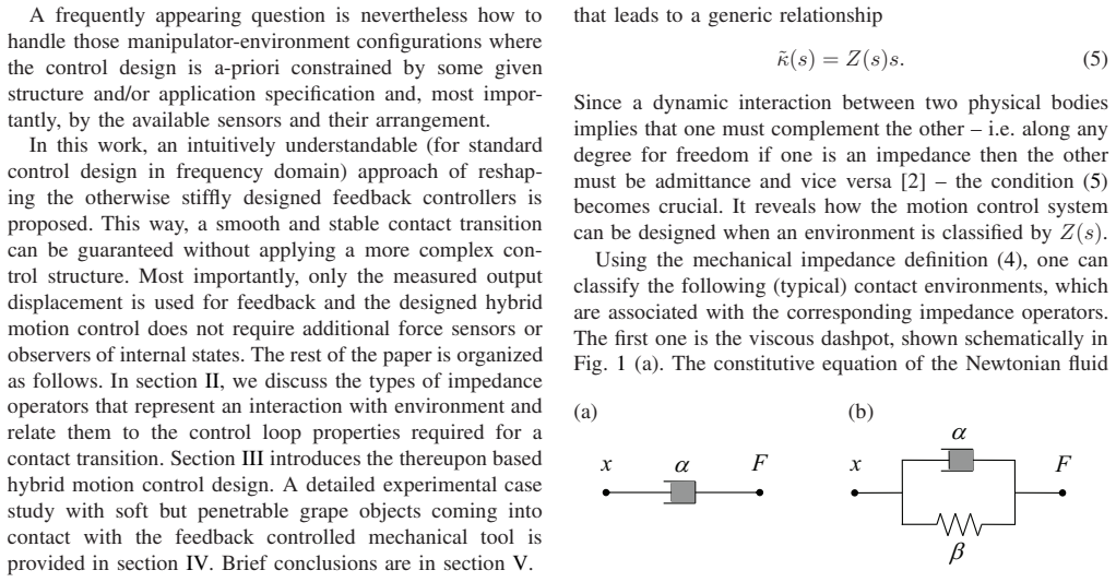
- domain assumption The contact environment is a linear time-invariant impedance belonging to the classes in Section II, namely viscous alpha or Kelvin-Voigt alpha+beta/s.
- domain assumption The disturbance force F(t) enters as a matched input at the plant input, so that u+F is the total force acting on the plant.
- ad hoc to paper The control signal threshold U can distinguish contact from friction, measurement noise, and tracking transients.
Cite this review
Pith. "Pith review of Loop Shaping of Hybrid Motion Control with Contact Transition." pith.science (2026). https://pith.science/paper/VQNCZCOH
@misc{pith2026241119495,
  author       = {Pith},
  title        = {Pith review of: Loop Shaping of Hybrid Motion Control with Contact Transition},
  year         = {2026},
  howpublished = {\url{https://pith.science/paper/VQNCZCOH}},
  note         = {Machine review of arXiv:2411.19495}
}
read the original abstract
A standard motion control with feedback of the output displacement cannot handle unforeseen contact with environment without penetrating into the soft, i.e. viscoelastic, materials or even damaging the fragile materials. Robotics and mechatronics with tactile and haptic capabilities, and in particular medical robotics for example, place special demands on the advanced motion control systems that should enable the safe and harmless contact transitions. This paper shows how the basic principles of loop shaping can be easily used to handle sufficiently stiff motion control in such a way that it is extended by sensor-free dynamic reconfiguration upon contact with the environment. A thereupon based hybrid control scheme is proposed. A remarkable feature of the developed approach is that no measurement of the contact force is required and the input signal and the measured output displacement are the only quantities used for design and operation. Experiments on 1-DOF actuator are shown, where the moving tool comes into contact with grapes that are soft and simultaneously penetrable.
Figures


Figures from the paper (4 more)


Reference graph
Works this paper leans on
-
[1]
Dynamic stability issues in for ce control of manipulators,
C. An and J. Hollerbach, “Dynamic stability issues in for ce control of manipulators,” in American Control Conference , 1987, pp. 821–827
work page 1987
-
[2]
Impedance control: An approach to manipulati on: Part I – theory,
N. Hogan, “Impedance control: An approach to manipulati on: Part I – theory,” Transactions of the ASME , vol. 107, no. 1, pp. 1–7, 1985
work page 1985
-
[3]
Hybrid impedance control of ro botic manipulators,
R. Anderson and M. Spong, “Hybrid impedance control of ro botic manipulators,” IEEE Journal on Robotics and Automation , vol. 4, no. 5, pp. 549–556, 1988
work page 1988
-
[4]
Controlling contact transitio n,
J. Hyde and M. Cutkosky, “Controlling contact transitio n,” IEEE Control Systems Magazine , vol. 14, no. 1, pp. 25–30, 1994
work page 1994
-
[5]
Force control of robot manipulators,
T. Y oshikawa, “Force control of robot manipulators,” in IEEE Inter- national Conference on Robotics and Automation , 2000, pp. 220–226
work page 2000
-
[6]
L. Villani and J. De Schutter, “Force control,” in Springer Handbook of Robotics , pp. 195–220, 2016
work page 2016
-
[7]
Estimation, identifi cation, and sensorless control in motion control system,
K. Ohnishi, N. Matsui, and Y . Hori, “Estimation, identifi cation, and sensorless control in motion control system,” Proceedings of the IEEE , vol. 82, no. 8, pp. 1253–1265, 1994
work page 1994
-
[8]
A. Albu-Sch¨ affer, C. Ott, and G. Hirzinger, “A unified pa ssivity- based control framework for position, torque and impedance control of flexible joint robots,” The International Journal of Robotics Research , vol. 26, no. 1, pp. 23–39, 2007
work page 2007
Show all 24 references
-
[9]
Hybrid position/force control of manipula- tors,
M. Raibert and J. Craig, “Hybrid position/force control of manipula- tors,” ASME Journal of Dynamic Systems, Measurement, and Control , vol. 103, no. 2, pp. 126–133, 1981
1981
-
[10]
V ariable impedance control of redundant manipulators for intuitive human–robot physi cal interac- tion,
F. Ficuciello, L. Villani, and B. Siciliano, “V ariable impedance control of redundant manipulators for intuitive human–robot physi cal interac- tion,” IEEE Tran. on Robotics , vol. 31, no. 4, pp. 850–863, 2015
2015
-
[11]
Hybrid position/force con trol for hy- draulic actuators,
P . Pasolli and M. Ruderman, “Hybrid position/force con trol for hy- draulic actuators,” in IEEE 28th Mediterranean Conference on Control and Automation (MED) , 2020, pp. 73–78
2020
-
[12]
Basic problems in stabilit y and design of switched systems,
D. Liberzon and A. S. Morse, “Basic problems in stabilit y and design of switched systems,” IEEE Control Systems Magazine , vol. 19, pp. 59–70, 1999
1999
-
[13]
On switching between motion and force con trol,
M. Ruderman, “On switching between motion and force con trol,” in IEEE 27th Mediterranean Conference on Control and Automati on (MED), 2019, pp. 445–450
2019
-
[14]
Accuracy/robustness dilemma in impedance control,
T. V alency and M. Zacksenhouse, “Accuracy/robustness dilemma in impedance control,” ASME Journal of dynamic systems, measurement, and control, vol. 125, no. 3, pp. 310–319, 2003
2003
-
[15]
A hybrid system f ramework for unified impedance and admittance control,
C. Ott, R. Mukherjee, and Y . Nakamura, “A hybrid system f ramework for unified impedance and admittance control,” Journal of Intelligent & Robotic Systems , vol. 78, pp. 359–375, 2015
2015
-
[16]
Motion-contr ol tech- niques of today and tomorrow: a review and discussion of the c hal- lenges of controlled motion,
M. Ruderman, M. Iwasaki, and W.-H. Chen, “Motion-contr ol tech- niques of today and tomorrow: a review and discussion of the c hal- lenges of controlled motion,” IEEE Industrial Electronics Magazine , vol. 14, no. 1, pp. 41–55, 2020
2020
-
[17]
Spong, S
M. Spong, S. Hutchinson, and M. Vidyasagar, Robot Modeling and Control. John Wiley & Sons, 2005
2005
-
[18]
K. J. ˚Astr¨ om and R. Murray, Feedback systems: an introduction for scientists and engineers . Princeton University Press, 2021
2021
-
[19]
Ruderman, Analysis and compensation of kinetic friction in robotic and mechatronic control systems
M. Ruderman, Analysis and compensation of kinetic friction in robotic and mechatronic control systems . CRC Press, 2023
2023
-
[20]
G uaranteeing prescribed performance and contact maintenance via an appr oximation free robot force/position controller,
C. P . Bechlioulis, Z. Doulgeri, and G. A. Rovithakis, “G uaranteeing prescribed performance and contact maintenance via an appr oximation free robot force/position controller,” Automatica, vol. 48, no. 2, pp. 360–365, 2012
2012
-
[21]
Collision detection and safe reaction with the DLR-III lig htweight manipulator arm,
A. De Luca, A. Albu-Schaffer, S. Haddadin, and G. Hirzin ger, “Collision detection and safe reaction with the DLR-III lig htweight manipulator arm,” in 2006 IEEE/RSJ International Conference on Intelligent Robots and Systems , 2006, pp. 1623–1630
2006
-
[22]
Motion control with optimal nonlinear da mping: from theory to experiment,
M. Ruderman, “Motion control with optimal nonlinear da mping: from theory to experiment,” Control Engineering Practice , vol. 127, p. 105310, 2022
2022
-
[23]
Dis turbance sensitivity analysis and experimental evaluation of conti nuous sliding mode control,
M. Ruderman, J. Reger, B. Calmbach, and L. Fridman, “Dis turbance sensitivity analysis and experimental evaluation of conti nuous sliding mode control,” arXiv preprint arXiv:2208.06608 , 2022
2022 arXiv
-
[24]
On convergence analysis of feedback cont rol with inte- gral action and discontinuous relay perturbation,
M. Ruderman, “On convergence analysis of feedback cont rol with inte- gral action and discontinuous relay perturbation,” Comm. in Nonlinear Science and Numerical Simulation , vol. 145, p. 108698, 2025
2025
Reviewed August 12, 2026 · model on record in the stance chip above.
Discussion (0). Continue with ORCID to comment.