REVIEW 3 major objections 5 minor 2 cited by
Reactor-scale stellarators with force and torque minimized dipole coils
T0 review · 3 major / 5 minor · reviewed 2026-08-11 · deepseek-v4-flash
Pith's one-line read The first reactor-scale stellarator magnet design with tolerable forces on a planar dipole array.
desk verdict A serious, reproducible optimization advance; the reactor-scale 'tolerable forces' claim needs an engineering asterisk before it fully lands. read the letter →
The pith
A machine-rendered reading of the paper's core claim, the machinery that carries it, and where it could break.
The reading
What carries the argument
The load-bearing machinery is a set of new optimization objectives computed by autodifferentiation: pointwise force per unit length and torque per unit length on each filamentary coil, their net integrated values, and the full inductance matrix, all from Biot-Savart and Neumann-type integrals. These are combined with penalties on field error, coil-plasma distance, coil-coil distance, linking number, and toroidal-field coil length and curvature, and minimized with L-BFGS. The planar-coil representation uses a fixed circular radius, a center position, and a quaternion orientation, so the optimizer can rotate and translate each dipole without gimbal lock; the paper's ablation study shows these degrees of freedom are what allow forces and torques to reach tolerable levels.
What would settle it
Run a coupled structural and superconducting analysis of one of the reported coil sets, such as a 100-turn, meter-radius planar dipole carrying 14 to 16 MA at 5.7 T with a 10 cm by 10 cm winding pack; if the peak stress exceeds the cable's measured limit, if the critical current at 5.7 T and 4.2 K requires more conductor area than assumed, or if quench protection forces a lower current, the tolerable-load claim is falsified. A cheaper test is to rerun the optimization with the pointwise force threshold cut from 1.0 to 0.7 MN/m and the net dipole torque threshold cut from 6 to 4 MN·m, then check whether any solution at similar field error still exists.
Extended reading notes
Core claim
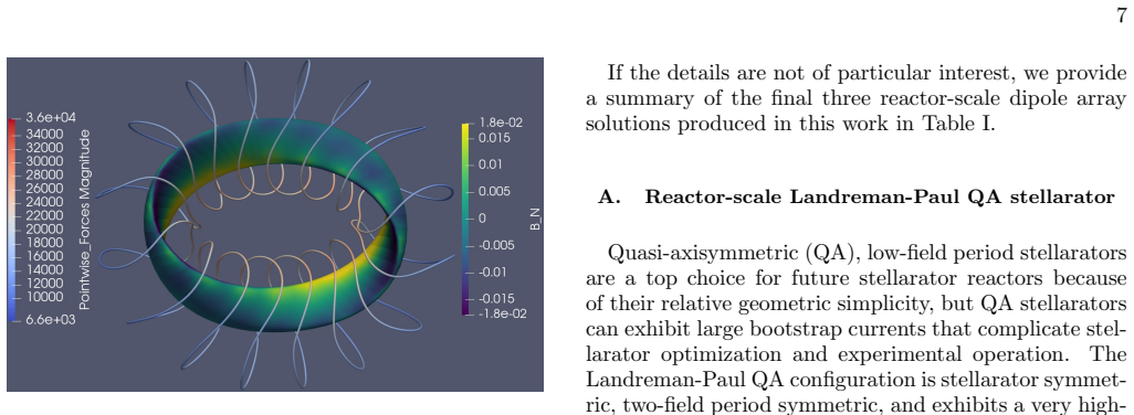
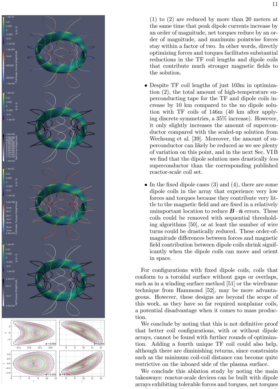
Using differentiable coil objectives for pointwise and net Lorentz forces and torques, the paper jointly optimizes a small set of nonplanar toroidal-field coils together with arrays of planar circular dipole coils. Each dipole carries eight degrees of freedom (center position, quaternion orientation, current) and the optimizer is allowed to move and reorient every coil. Applied to three reactor-scale quasi-symmetric stellarator configurations at 5.7 T on axis, 1.7 m minor radius, and a 1.5 m minimum plasma-coil distance, the method yields the first dipole-array solutions whose maximum pointwise forces (about 1 MN/m), net dipole torques (5 to 7 MN·m), toroidal-field torques (38 to 130 MN·m), coil-coil distances, and field errors are all called tolerable. The paper states explicitly that this is the first dipole array solution with tolerable forces, torques, coil-coil distances, and related constraints for a reactor-scale stellarator.
Load-bearing premise
The entire feasibility conclusion rests on extrapolated engineering load limits—about 1 MN/m pointwise force, roughly 6 MN net force and 6 MN·m net torque per dipole, and about 400 MN·m on the toroidal-field coils—being valid for roughly 100-turn, meter-radius dipole coils carrying 9.5 to 16 MA at 5.7 T, even though the paper does not model critical current, quench, or structural mechanics for the final geometries.
Editorial extensions
If this is right
- Stellarator reactors can be designed with magnet sets made mostly of identical, planar, mass-producible dipole coils, reserving complex geometry for a small number of toroidal-field coils.
- Letting dipole coils move and rotate during optimization is essential in the reactor-scale regime; with fixed locations and orientations, force and torque penalties cannot keep peak loads within limits without lengthening the toroidal-field coils or degrading accuracy.
- Directly minimizing net torques is efficient: net torques can be driven down by orders of magnitude with minimal degradation of field error or forces, which simplifies support-structure requirements.
- The dipole-array solutions reduce the number, length, and complexity of the toroidal-field coils relative to the modular-coil baselines examined in the paper, with one quasi-helically symmetric case cutting the high-temperature superconductor tape requirement by about 16 percent.
Reading between the lines
- If the load tolerances hold up under structural analysis, the economic case for stellarators shifts: the dominant magnet cost moves from precision manufacturing of complex three-dimensional coils to mass production of flat coils plus a support frame that lets each coil be positioned and oriented individually.
- Because dipole fields decay as distance cubed, the 1.5 m blanket standoff is one of the strongest drivers of current and force; the paper's comparison with thinner-blanket designs implies that a moderate reduction in standoff could bring the marginal compact case's 16 MA, 1.3 MN/m operating point comfortably inside limits, a scaling that could be tested by recomputing the same optimizations at 1.0
- The result that net torques are nearly free to minimize suggests a design principle for future arrays: optimize orientations first to null net torques, then use remaining degrees of freedom for pointwise force mitigation and field accuracy; a staged optimization following this recipe could be tested against the joint optimization used here.
- The ablation's fixed-coil cases contained some dipoles that carried almost no current or force, which points toward a hybrid design where a fixed dipole layer is reserved for active error-field control while a smaller set of movable, high-current dipoles does the main field shaping.
Editorial analysis
A structured set of objections, weighed in public.
Referee Report
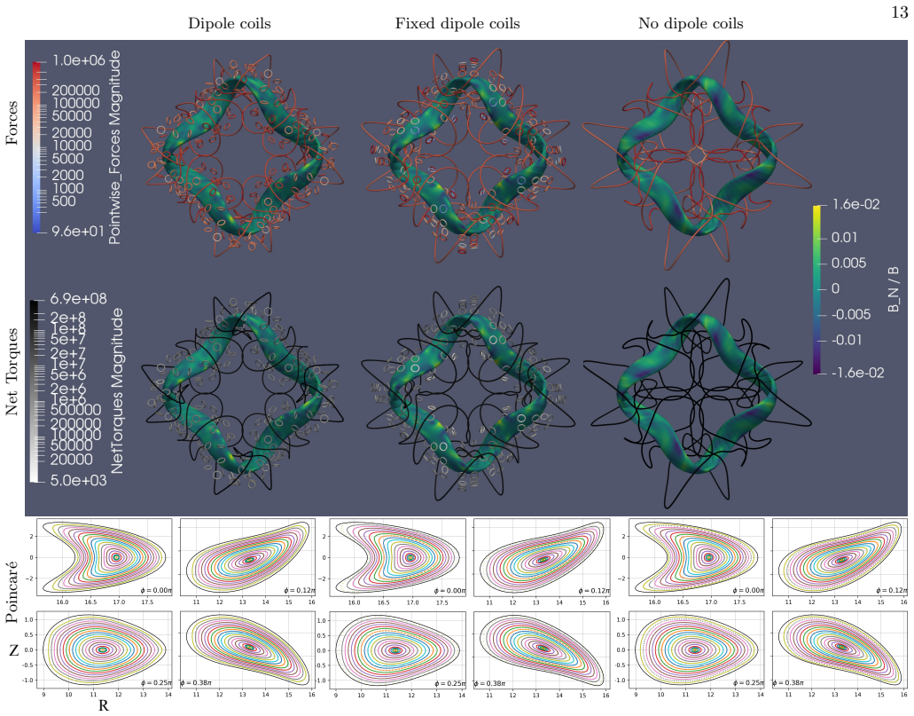
Summary. The paper develops new coil-optimization objectives for pointwise and net Lorentz forces and torques, implemented with automatic differentiation in SIMSOPT, and uses them to jointly optimize arrays of planar dipole coils together with a small number of nonplanar TF coils. The method is applied to three reactor-scale quasi-symmetric stellarator configurations (Landreman-Paul QA, Landreman-Paul QH, and Schuett-Henneberg QA) scaled to ARIES-CS parameters, with a minimum plasma-coil distance of 1.5 m. The paper claims that these are the first dipole-array stellarator solutions with tolerable forces, torques, and coil-coil distances at reactor scale, while substantially reducing the number and complexity of TF coils. The authors validate the new objectives against finite differences and a standard stage-two coil optimization benchmark, perform an ablation study showing the importance of allowing dipole positions and orientations to vary and of directly minimizing force/torque terms, and check the final field quality with Poincaré plots, quadratic-flux-minimizing surfaces, and VMEC.
Significance. If the claims hold, the paper is a significant step toward reactor-scale stellarators with mass-producible planar dipole coils and much simpler TF coils. The strengths include the careful validation of the new force and torque objectives against finite differences and a standard benchmark, the open-source implementation with archived configuration files, the systematic ablation study, and the end-to-end verification of field quality with Poincaré plots, QFM surfaces, and VMEC. These elements make the optimization results reproducible and the field-accuracy part of the claim well supported. The main caveat is that the 'tolerable' and 'reactor-scale feasibility' conclusions rest on engineering estimates that are approximate and not backed by structural or superconductor analysis for the final geometries, so the headline feasibility claim is conditional rather than fully demonstrated.
major comments (3)
- [Sec. VI and Table I] Sec. VI sets explicit acceptance thresholds: maximum force loads ≲ 1 MN/m, maximum dipole net torque ∼6 MN-m, and minimum TF-TF distance 0.8 m. Table I reports a maximum dipole force of 1.3 MN/m and a maximum dipole net torque of 7.1 MN-m for the Schuett-Henneberg QA solution, and Sec. VI B reports a final minimum TF-TF distance of 0.79 m. None of these exceedances is acknowledged or justified; the only tolerance assessment in Sec. VI A 1 states that the QA solution is 'roughly within material tolerances.' Consequently, the unqualified claim of 'tolerable forces, torques, ... for a reactor-scale stellarator' (abstract and Sec. VI A 1) is not supported for all three finalized designs. The authors must either justify the relaxed limits for these cases or report explicitly which acceptance criteria are satisfied by each design.
- [Sec. VI and footnote 1] The feasibility conclusion rests on engineering limits extrapolated from VIPER/SPARC cable loads to 100-turn, ~1 m radius dipole coils carrying 9.5–16 MA at 5.7 T. Footnote 1 explicitly states that critical current and quench are not modeled, that the 5x5 cm winding-pack assumption used for self-forces is a 'slight mismatch' with the later 10x10 cm cross-section, and Sec. VI presents no structural mechanics or support-structure analysis for any final geometry. Because the central claim is that the solutions are reactor-scale and 'tolerable,' the paper needs either a more quantitative structural/superconductor assessment for the final coil geometries or a clearly stated qualification that the feasibility demonstration is contingent on these approximate limits holding.
- [Sec. VI and Table I] The search criteria include a maximum tolerable net dipole force of ~6 MN, but the paper never reports the final net dipole force for any of the three optimized designs; Table I and the per-design discussions only give per-unit-length maximum forces and net torques. Without the final net dipole force values, the claim that the solutions satisfy the net-force tolerance cannot be verified. Please report the achieved net dipole forces or remove this criterion from the acceptance thresholds.
minor comments (5)
- [Sec. VI B and Fig. 7] Fig. 7 reports peak net torques of 4.2e8 N-m and 2.0e8 N-m for the 'dipole coils' and 'fixed dipole coils' cases, while Table I lists the final QH maximum dipole net torque as 5.7 MN-m after the follow-up optimization. Please state explicitly in the caption or text that Fig. 7 shows the intermediate first-round solutions, not the final design of Table I; as written, the two sets of numbers appear contradictory.
- [Abstract and Sec. VI A 1] The phrase 'first dipole array solution' should be qualified in light of the Thea Energy reactor-scale planar coil arrays discussed in Sec. I (refs. [25–27]); if the claimed priority is specifically about force/torque-minimized or joint TF-dipole optimization, that distinction should be stated explicitly to avoid an overbroad priority claim.
- [Eq. (14)] The symbol M is used for the Fourier mode order in Eqs. (1)–(3) and also for the quasisymmetry helicity in Eq. (14); renaming one of them would improve readability.
- [Sec. V] The statement 'The forces vary inversely with the number of turns of wire' is ambiguous: for a fixed total coil current, the Lorentz force on the winding pack is independent of the number of turns, whereas the force per turn scales as 1/N. Please specify what quantity is held fixed when the number of turns is changed.
- [Sec. VI A 1] Minor language issue: 'achieve essentially the same normalized error ... than the ... solution' should read 'as the ... solution.'
Circularity Check
No significant circularity: the force- and torque-minimized dipole array designs are produced by direct optimization with independently validated coil physics, not by a fitted parameter or self-citation chain.
full rationale
The paper's central claim is a design-feasibility demonstration. The coil force/torque and inductance objectives are defined from the Biot-Savart and Neumann integral formulas (Eqs. 9-12) and implemented via autodifferentiation. These implementations are checked against finite differences and against a standard SIMSOPT stage-two benchmark (Sec. V), and the self-force/self-inductance formulas from the authors' prior work [31-33] are independently published and reproduced as tooling; they do not encode the conclusion that reactor-scale dipole-array stellarators are feasible. The 'tolerable' force and torque limits in Sec. VI are engineering estimates extrapolated from VIPER/SPARC cable data (approximately 1 MN/m pointwise force, 6 MN net dipole force, 6 MN-m net dipole torque, 400 MN-m TF torque) and are used as optimization targets. Reporting that optimized designs approach these limits is constraint satisfaction, not a prediction forced by construction. No load-bearing step reduces to a self-citation, and no use is made of a uniqueness theorem from the authors' prior work. The caveats are engineering-risk issues rather than circularity: footnote 1 explicitly states that critical current and quench are not modeled and that the 5x5 cm winding-pack cross-section is a 'slight mismatch'; and Table I reports a maximum dipole force of 1.3 MN/m for the Schuett-Henneberg solution, above the stated ~1 MN/m search target, so 'tolerable' is applied non-uniformly. These qualifications do not make the optimization-derived results circular.
Assumptions & free parameters
free parameters (8)
- Pointwise force tolerance =
~1 MN/m
- Net dipole force tolerance =
~6 MN
- Net dipole torque tolerance =
~6 MN-m
- Net TF torque tolerance =
~400 MN-m
- Number of wire turns =
TF 200, dipole 100
- Objective weights and thresholds =
11 weights, 7 thresholds; several zero
- Unique dipole coil count =
41 QA, 27 QH, 16 SH
- Dipole coil radius =
0.743 m QA, 0.792 m QH, 0.783 m SH
assumptions (6)
- standard math Biot-Savart law for filamentary coils
- domain assumption Filamentary approximation with regularized self-force
- domain assumption Fixed plasma boundary, vacuum field matching
- domain assumption Material force and torque limits are representative
- domain assumption Target configurations are valid reactor-scale quasisymmetric designs
- ad hoc to paper L-BFGS from selected initial conditions finds representative local minima
Cite this review
Pith. "Pith review of Reactor-scale stellarators with force and torque minimized dipole coils." pith.science (2026). https://pith.science/paper/MHUSDA7D
@misc{pith2026241213937,
  author       = {Pith},
  title        = {Pith review of: Reactor-scale stellarators with force and torque minimized dipole coils},
  year         = {2026},
  howpublished = {\url{https://pith.science/paper/MHUSDA7D}},
  note         = {Machine review of arXiv:2412.13937}
}
read the original abstract
In this work, we utilize new coil objectives for stellarator optimization with autodifferentiation, including pointwise and net coil-coil forces and torques. We use these methods to perform the first large-scale optimization of planar dipole coil arrays, since arrays of small and geometrically simple coils have been proposed to partially produce the 3D magnetic fields for stellarators, generate advantageous magnetic field perturbations in tokamaks, and provide active, real-time control capabilities. We perform an ablation study to show that minimizing the orientation and location of each coil may be essential to get coil forces, coil torques, and field errors to tolerable levels. We conclude with solutions for three reactor-scale quasi-symmetric stellarators by jointly optimizing nonplanar TF coils and planar coil arrays.
Figures


Figures from the paper (11 more)




Forward citations
Cited by 2 Pith papers
-
Optimization of passive superconductors for shaping stellarator magnetic fields
First joint optimization of passive superconducting coil arrays and background fields produces low-error magnetic field solutions for four stellarators.
-
Agentic Stage-One Stellarator Optimization: Autonomous Multi-Objective Search for Finite-Beta Equilibria
An LLM-controlled outer loop around the DESC solver improved finite-beta stellarator designs, boosting gate-valid configurations from 5 of 23 to 19 of 23, with median quasisymmetry error cut roughly in half.
Reference graph
Works this paper leans on
-
[1]
Reactor-scale dipole array solution We begin by illustrating force and torque optimized results using a dipole array. We achieve essentially the same normalized error ⟨B · ˆn⟩/⟨B⟩ ≈3.4 × 10⁻³ than the (rescaled) four coil solution in Wechsung et al. with 182.3m total coil length, but use three shorter TF coils with lengths 33.6, 33.8, and 35.6 meters for ...
-
[2]
Ablation study After obtaining a suitable reactor-scale dipole array configuration with tolerable forces and torques, we pur- sued an ablation study where we sequentially remove coils, terms in the objective, or degree of freedoms in the coils, and see how the solution changes. We per- formed the following optimizations: we (1) optimize the dipole coils, ...
-
[3]
L.-M. Imbert-Gerard, E. J. Paul, and A. M. Wright, An introduction to stellarators: From magnetic fields to symmetries and optimization, arXiv preprint arXiv:1908.05360 (2019)
arXiv 2019
-
[4]
J. N¨ uhrenberg and R. Zille, Quasi-helically symmetric toroidal stellarators, Physics Letters A 129, 113 (1988)
work page 1988
- [5]
-
[6]
M. Drevlak, C. Beidler, J. Geiger, P. Helander, and Y. Turkin, Optimisation of stellarator equilibria with ROSE, Nuclear Fusion 59, 016010 (2018)
work page 2018
-
[7]
Landreman, B
M. Landreman, B. Medasani, F. Wechsung, A. Giuliani, R. Jorge, and C. Zhu, SIMSOPT: A flexible framework for stellarator optimization, Journal of Open Source Soft- ware 6, 3525 (2021)
2021
-
[8]
D. W. Dudt, R. Conlin, D. Panici, and E. Kolemen, The DESC stellarator code suite Part 3: Quasi-symmetry optimization, Journal of Plasma Physics 89, 955890201 (2023)
work page 2023
Show all 58 references
-
[9]
Landreman and E
M. Landreman and E. Paul, Magnetic fields with precise quasisymmetry for plasma confinement, Physical Review Letters 128, 035001 (2022)
2022
-
[10]
P. Kim, S. Buller, R. Conlin, W. Dorland, D. W. Dudt, R. Gaur, R. Jorge, E. Kolemen, M. Landreman, N. R. Mandell, et al., Optimization of nonlinear turbulence in stellarators, Journal of Plasma Physics 90, 905900210 (2024)
2024
-
[11]
Hegna, D
C. Hegna, D. Anderson, A. Bader, T. Bechtel, A. Bhat- tacharjee, M. Cole, M. Drevlak, J. Duff, B. Faber, S. Hudson, et al., Improving the stellarator through advances in plasma theory, Nuclear Fusion 62, 042012 (2022)
2022
-
[12]
Erckmann, H.-J
V. Erckmann, H.-J. Hartfuss, M. Kick, H. Ren- ner, J. Sapper, F. Schauer, E. Speth, F. Wes- ner, F. Wagner, M. Wanner, et al., The W7-X project: Scientific basis and technical realization, in 17th IEEE/NPSS Symposium Fusion Engineering, Vol. 1 (IEEE, 1997) pp. 40–48
1997
-
[13]
Strykowsky, T
R. Strykowsky, T. Brown, J. Chrzanowski, M. Cole, P. Heitzenroeder, G. H. Neilson, D. Rej, and M. Viol, Engineering cost & schedule lessons learned on NCSX, in 2009 23rd IEEE/NPSS Symposium on Fusion Engineering (IEEE, 2009) pp. 1–4
2009
-
[14]
T. Qian, M. Zarnstorff, D. Bishop, A. Chamblis, A. Dominguez, C. Pagano, D. Patch, and C. Zhu, Simpler optimized stellarators using permanent magnets, Nuclear Fusion 62, 084001 (2022)
2022
-
[15]
Hammond, C
K. Hammond, C. Zhu, T. Brown, K. Corrigan, D. Gates, and M. Sibilia, Geometric concepts for stellarator perma- nent magnet arrays, Nuclear Fusion 60, 106010 (2020)
2020
-
[16]
A. A. Kaptanoglu, R. Conlin, and M. Landreman, Greedy permanent magnet optimization, Nuclear Fusion 63, 036016 (2022)
2022
-
[17]
A. A. Kaptanoglu, T. Qian, F. Wechsung, and M. Lan- dreman, Permanent-magnet optimization for stellarators as sparse regression, Physical Review Applied 18, 044006 (2022)
2022
-
[18]
Hammond and A
K. Hammond and A. Kaptanoglu, Improved stellarator permanent magnet designs through combined discrete and continuous optimizations, Computer Physics Com- munications , 109127 (2024)
2024
-
[19]
G. Yu, K. Liu, T. Qian, Y. Xie, X. Nie, and C. Zhu, Quasi-single-stage optimization for permanent magnet stellarators, Nuclear Fusion 64, 076055 (2024)
2024
-
[20]
T. Qian, X. Chu, C. Pagano, D. Patch, M. Zarnstorff, B. Berlinger, D. Bishop, A. Chambliss, M. Haque, D. Sei- dita, et al., Design and construction of the MUSE perma- nent magnet stellarator, Journal of Plasma Physics 89, 955890502 (2023)
2023
-
[21]
Gates, S
D. Gates, S. Aslam, B. Berzin, A. Cote, D. Dudt, 17 Coil-surface distance [m] Max coil length [m] Max force [N/m] FIG. 12: Significant correlation trends are observed from several thousand pointwise torque optimizations. Larger minimum coil-surface distance, larger coil forces...
2023
-
[22]
Zarnstorff, A
M. Zarnstorff, A. Bhattacharjee, R. Carty, and S. Team, The Stellarex Path to a Stellarator Fusion Pilot Plant, in APS Division of Plasma Physics Meeting Abstracts, Vol. 2023 (2023) pp. CM06–009
2023
-
[23]
Williamson, A
D. Williamson, A. Brooks, T. Brown, M. Cole, H.-M. Fan, P. Goranson, M. Hechler, P. Heitzen- roeder, B. Nelson, and W. Reiersen, Design de- scription of the saddle coils for the National Compact Stellarator Experiment (NCSX), in 18th IEEE/NPSS Symposium on Fusion Engineering (...
1999
-
[24]
Baillod, E
A. Baillod, E. Paul, G. Rawlinson, M. Haque, S. Freiberger, and S. Thapa, Integrating Novel Stel- larator Single-Stage Optimization Algorithms to Design the Columbia Stellarator Experiment, arXiv preprint arXiv:2409.05261 (2024)
2024 arXiv
-
[25]
Helander, M
P. Helander, M. Drevlak, M. Zarnstorff, and S. Cowley, Stellarators with permanent magnets, Physical review letters 124, 095001 (2020)
2020
-
[26]
Bradbury, James and Frostig, Roy and Hawkins, Pe- ter and Johnson, Matthew James and Leary, Chris and Maclaurin, Dougal and Necula, George and Paszke, Adam and VanderPlas, Jake and Wanderman-Milne, Skye, JAX: composable transformations of Python+ NumPy programs, (2018)
2018
-
[27]
R. Wu, T. Kruger, and C. Swanson, Planar coil opti- mization for the Eos stellarator using sparse regression, Plasma Physics and Controlled Fusion67, 035019 (2025). 19
2025
-
[28]
Gates, S
D. Gates, S. Aslam, B. Berzin, P. Bonofiglo, A. Cote, D. Dudt, E. Flom, D. Fort, A. Koen, T. Kruger, et al., Stellarator fusion systems enabled by arrays of planar coils, Nuclear Fusion 65, 026052 (2025)
2025
-
[29]
Kruger, M
T. Kruger, M. Martin, D. Gates, et al., Coil optimization methods for a planar coil stellarator, Nuclear Fusion 65, 026051 (2025)
2025
-
[30]
Hegna, D
C. Hegna, D. Anderson, E. Andrew, A. Ayilaran, A. Bader, T. Bohm, K. C. Mata, J. Canik, L. Car- bajal, A. Cerfon, et al., The Infinity Two Fusion Pilot Plant baseline plasma physics design, Journal of Plasma Physics , 1 (2025)
2025
-
[31]
Robin and F
R. Robin and F. A. Volpe, Minimization of magnetic forces on stellarator coils, Nuclear Fusion 62, 086041 (2022)
2022
-
[32]
L. Fu, E. J. Paul, A. A. Kaptanoglu, and A. Bhat- tacharjee, Global stellarator coil optimization with quadratic constraints and objectives, arXiv preprint arXiv:2408.08267 (2024)
2024 arXiv
-
[33]
Hurwitz, M
S. Hurwitz, M. Landreman, and T. M. Antonsen, Effi- cient calculation of the self magnetic field, self-force, and self-inductance for electromagnetic coils, IEEE Transac- tions on Magnetics (2024)
2024
-
[34]
Landreman, S
M. Landreman, S. Hurwitz, and T. M. Antonsen Jr, Ef- ficient calculation of self magnetic field, self-force, and self-inductance for electromagnetic coils. II. Rectangular cross-section, arXiv preprint arXiv:2310.12087 (2023)
2023 arXiv
-
[35]
Hurwitz, M
S. Hurwitz, M. Landreman, and A. Kaptanoglu, Elec- tromagnetic coil optimization for reduced Lorentz forces, arXiv preprint arXiv:2410.09337 (2024)
2024 arXiv
-
[36]
Guinchard, S
S. Guinchard, S. Hudson, and E. Paul, Including the vac- uum field energy in stellarator coil design, arXiv preprint arXiv:2409.01268 (2024)
2024
-
[37]
McGreivy, S
N. McGreivy, S. R. Hudson, and C. Zhu, Optimized finite-build stellarator coils using automatic differentia- tion, Nuclear Fusion 61, 026020 (2021)
2021
-
[38]
Wiedman, S
A. Wiedman, S. Buller, and M. Landreman, Coil opti- mization for quasi-helically symmetric stellarator con- figurations, Journal of Plasma Physics 90, 905900307 (2024)
2024
-
[39]
A. A. Kaptanoglu, M. Landreman, and M. C. Zarnstorff, Optimization of passive superconductors for shaping stel- larator magnetic fields, arXiv preprint arXiv:2501.12468 (2025)
2025 arXiv
-
[40]
C. Zhu, S. R. Hudson, Y. Song, and Y. Wan, New method to design stellarator coils without the winding surface, Nuclear Fusion 58, 016008 (2017)
2017
-
[41]
Wechsung, M
F. Wechsung, M. Landreman, A. Giuliani, A. Cerfon, and G. Stadler, Precise stellarator quasi-symmetry can be achieved with electromagnetic coils, Proceedings of the National Academy of Sciences 119, e2202084119 (2022)
2022
-
[42]
D. C. Liu and J. Nocedal, On the limited memory BFGS method for large scale optimization, Mathematical pro- gramming 45, 503 (1989)
1989
-
[43]
Bindel, M
D. Bindel, M. Landreman, and M. Padidar, Understand- ing trade-offs in stellarator design with multi-objective optimization, Journal of Plasma Physics 89, 905890503 (2023)
2023
-
[44]
Z. S. Hartwig, R. F. Vieira, B. N. Sorbom, R. A. Bad- cock, M. Bajko, W. K. Beck, B. Castaldo, C. L. Craighill, M. Davies, J. Estrada, et al., VIPER: an industrially scal- able high-current high-temperature superconductor ca- ble, Superconductor Science and Technology 33, 11LT...
2020
-
[45]
Z. Zhao, P. Moore, and L. Chiesa, Structural modeling of REBCO VIPER cable for high-field magnet applications, IEEE Transactions on Applied Superconductivity 32, 1 (2022)
2022
-
[46]
N. Riva, R. Granetz, R. Vieira, A. Hubbard, A. Pfeiffer, P. Harris, C. Chamberlain, Z. Hartwig, A. Watterson, D. Anderson, et al., Development of the first non-planar REBCO stellarator coil using VIPER cable, Supercon- ductor Science and Technology 36, 105001 (2023)
2023
-
[47]
Z. S. Hartwig, R. F. Vieira, D. Dunn, T. Golfinopoulos, B. LaBombard, C. J. Lammi, P. C. Michael, S. Agabian, D. Arsenault, R. Barnett, et al., The SPARC toroidal field model coil program, IEEE Transactions on Applied Superconductivity (2023)
2023
-
[48]
Molodyk, S
A. Molodyk, S. Samoilenkov, A. Markelov, P. Degt- yarenko, S. Lee, V. Petrykin, M. Gaifullin, A. Manke- vich, A. Vavilov, B. Sorbom, et al., Development and large volume production of extremely high current den- sity YBa2Cu3O7 superconducting wires for fusion, Sci- entific rep...
2021
-
[49]
R. L. Dewar, S. R. Hudson, and A. M. Gibson, Unified theory of ghost and quadratic-flux-minimizing surfaces, arXiv preprint arXiv:1001.0483 (2010)
2010 arXiv
-
[50]
Hirshman and J
S. Hirshman and J. Whitson, Steepest-descent mo- ment method for three-dimensional magnetohydrody- namic equilibria, The Physics of Fluids 26, 3553 (1983)
1983
-
[51]
Rodriguez, E
E. Rodriguez, E. Paul, and A. Bhattacharjee, Measures of quasisymmetry for stellarators, Journal of Plasma Physics 88 (2022)
2022
-
[52]
A. A. Kaptanoglu, C. Hansen, J. D. Lore, M. Landreman, and S. L. Brunton, Sparse regression for plasma physics, Physics of Plasmas 30, 033906 (2023)
2023
-
[53]
Ku and A
L. Ku and A. Boozer, Modular coils and plasma con- figurations for quasi-axisymmetric stellarators, Nuclear fusion 50, 125005 (2010)
2010
-
[54]
Hammond, A framework for discrete optimization of stellarator coils, arXiv preprint arXiv:2412.00267 (2024)
K. Hammond, A framework for discrete optimization of stellarator coils, arXiv preprint arXiv:2412.00267 (2024)
2024 arXiv
-
[55]
F. S. B. Anderson, A. F. Almagri, D. T. Anderson, P. G. Matthews, J. N. Talmadge, and J. L. Shohet, The he- lically symmetric experiment, (HSX) goals, design and status, Fusion Technology 27, 273 (1995)
1995
-
[56]
A. F. Almagri, D. T. Anderson, F. S. B. Anderson, P. H. Probert, J. L. Shohet, and J. N. Talmadge, A he- lically symmetric stellarator (HSX), IEEE Transactions on Plasma Science 27, 114 (1999)
1999
-
[57]
A. A. Kaptanoglu, G. P. Langlois, and M. Landre- man, Topology optimization for inverse magnetostatics as sparse regression: Application to electromagnetic coils for stellarators, Computer Methods in Applied Mechan- ics and Engineering 418, 116504 (2024)
2024
-
[58]
T. M. Schuett and S. A. Henneberg, Exploring novel compact quasi-axisymmetric stellarators, arXiv preprint arXiv:2409.00523 (2024)
2024 arXiv
Reviewed August 11, 2026 · model on record in the stance chip above.
Discussion (0). Continue with ORCID to comment.