REVIEW 4 major objections 5 minor 65 references
Continuously controllable dissipative and coherent couplings by the interaction between anti-resonance and multiple magnons
T0 review · 4 major / 5 minor · reviewed 2026-08-10 · deepseek-v4-flash
Pith's one-line read This paper claims that a single cavity anti-resonance mode can couple to different magnon modes either dissipatively or coherently, with the magnon mode's microwave magnetic field strength at the anti-resonance frequency deciding which…
desk verdict A genuinely new empirical correlation in cavity magnonics—dissipative versus coherent anti-resonance coupling tracks whether the magnon's rf field is weak or strong at the sample—shown in two cavities, but the 'law' stays qualitative. read the letter →
The pith
A machine-rendered reading of the paper's core claim, the machinery that carries it, and where it could break.
The reading
What carries the argument
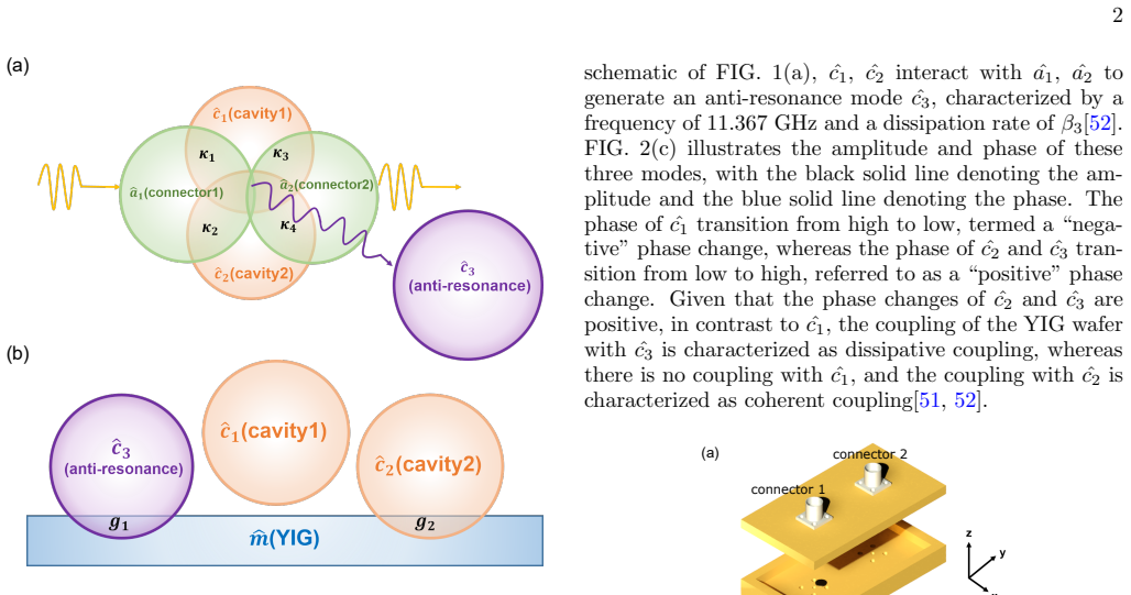
The load-bearing object is the anti-resonance mode $\hat{c}_3$, a transmission dip generated jointly by two cavity modes $\hat{c}_1,\hat{c}_2$ and two input/output connectors, at 11.367 GHz in the rectangular cavity and 13.05 GHz in the quadrant-stadium cavity. The fits are made with a non-Hermitian Hamiltonian whose magnon-photon interaction is a complex coupling $J - i\Gamma e^{i\theta}$, where $J$ is the coherent coupling strength, $\Gamma$ the dissipative coupling strength, and $\theta$ the phase difference of the microwave drive at the two ports; its two eigenvalues give the level repulsion or level attraction used to extract the numbers in Table I. The second piece of machinery is finite-element simulation of the microwave magnetic field of each magnon mode at the anti-resonance frequency, which supplies the weak-field/strong-field distinction that the paper correlates with dissipative/coherent character. The magnon modes themselves are identified using the Kittel equation for FMR and the Damon-Eshbach dispersion for FVMSW, with wave vectors from Bessel-function roots.
What would settle it
Place the YIG wafer at a cavity position where finite-element simulation predicts a strong microwave magnetic field for the FMR mode at the anti-resonance frequency and measure the coupling; the paper's rule predicts coherent coupling, so observing dissipative coupling in that configuration would falsify the claim.
Extended reading notes
Core claim
The paper's central claim is that, in a quasi-closed microwave cavity loaded with a yttrium iron garnet (YIG) wafer, the same anti-resonance mode can couple to different magnon modes in opposite ways depending on the microwave magnetic field of the magnon mode at the anti-resonance frequency. At the anti-resonance at 11.367 GHz in the rectangular cavity, the ferromagnetic resonance (FMR) mode has a weak field at the wafer and couples dissipatively, with fitted strengths $\Gamma/2\pi = 70$ MHz and $J/2\pi = 1$ MHz, while the forward volume magnetostatic spin wave (FVMSW) modes have strong fields and couple coherently, the lowest-order mode with $\Gamma/2\pi = 5$ MHz and $J/2\pi = 40$ MHz. The same pattern is reproduced in a quadrant-stadium (chaotic) cavity at the anti-resonance at 13.05 GHz, where the coupling type alternates between dissipative and coherent as successive magnon modes cross the anti-resonance, and finite-element simulations of the magnon field distributions match the assignment: weak field means dissipative, strong field means coherent. The authors conclude that dissipative coupling appears only at the anti-resonance frequency and only when the magnon mode's microwave field at that frequency is as weak as possible, and they use the alternating couplings to make microwave transmission at the anti-resonance frequency switchable by applied magnetic field.
Load-bearing premise
The central claim depends on the criterion, taken from earlier work on cavity anti-resonances, that the sign of the cavity mode's phase change at the anti-resonance tells whether a coupling is dissipative or coherent; if that phase-based labeling is wrong for this multimode geometry, the dissipative/coherent assignments and the field-strength correlation would have to be redone.
Editorial extensions
If this is right
- A single anti-resonance mode can replace the usual either-or choice in cavity magnonics: different magnon modes in the same sample give dissipative and coherent coupling at the same cavity frequency.
- The weak-field/strong-field rule becomes a geometric design criterion for placing magnetic samples in quasi-closed cavities.
- Because the applied magnetic field moves successive magnon modes through the anti-resonance, the system alternates between the two coupling regimes and acts as a continuously tunable microwave switch.
- In the chaotic cavity, the competition between coherent and dissipative coupling suppresses the lower polariton branch, which sharpens the transmission windows observed at the anti-resonance.
- Systems that need both coupling types together, for example for nonreciprocal or long-distance magnon-photon control, can now be built with one cavity instead of separate setups.
Reading between the lines
- The paper fits $\Gamma$ and $J$ separately for each mode; a parameter-free extension would be to compute the overlap integral between the magnon mode's microwave field and the cavity field at the anti-resonance and predict the ratio $\Gamma/J$ from it.
- The geometric rule suggests a design path the paper does not explore: patterning a magnetic film so that selected magnon modes have nodal, weak-field profiles at the anti-resonance frequency would let one engineer dissipative coupling on demand.
- The same weak-field/strong-field correlation may hold in other quasi-closed cavity geometries and other magnetic materials, which could turn the demonstrated rule into a general platform rule rather than a YIG-specific effect.
- If the phase-change criterion and the field-strength rule are connected, then a direct measurement of the complex transmission phase across each avoided crossing should determine the coupling type without separate fits; that would be a sharp test of the mechanism.
Editorial analysis
A structured set of objections, weighed in public.
Referee Report
Summary. The manuscript reports cavity-magnonics experiments in a rectangular (integrable) cavity and a quadrant-stadium (chaotic) cavity, in which a single anti-resonance mode at 11.367 GHz and 13.05 GHz respectively interacts with the ferromagnetic resonance (FMR) mode and several forward volume magnetostatic spin-wave (FVMSW) modes of a YIG wafer. By fitting transmission dispersions branch by branch with the two-mode non-Hermitian Hamiltonian in Eq. (4), the authors classify each magnon branch as either coherently or dissipatively coupled to the anti-resonance. They observe that modes whose simulated microwave magnetic field at the anti-resonance frequency is weak tend to be dissipatively coupled, while modes with stronger field distributions tend to be coherently coupled. On this basis they propose a field-distribution design rule and demonstrate a field-controlled transmission feature at the anti-resonance frequency, which they propose as a magnetic-tuning switch.
Significance. If established, the claimed rule would be a practical design principle for engineering coherent versus dissipative magnon-photon coupling without changing material parameters. The paper is valuable in showing both coupling types with the same anti-resonance mode and in testing the idea in two qualitatively different cavities, with raw transmission maps and explicit J/Γ values in Table I that are useful data. However, the quantitative support for the central correlation is currently insufficient: the field-strength comparison is qualitative and scale-dependent, the Eq. (4) fits carry no uncertainties, some labels are close to the coherent/dissipative boundary, and the correlation is demonstrated on the same data from which the labels were extracted rather than through an independent prediction. These issues must be addressed before the central claim is established.
major comments (4)
- [Results and discussion, Figs. 3(b)-(c) and 5(b)-(c)] The paper's load-bearing claim is that the magnon-mode field strength at the anti-resonance frequency determines the coupling type. This is supported only by qualitative inspection of color maps labeled 'Min'/'Max'. Because each panel appears normalized to its own maximum and the eigenmode simulations have arbitrary global amplitude, 'weak' versus 'strong' is not a scale-invariant quantity, and no threshold is defined. In addition, the correlation is demonstrated on the same data used to extract the labels, so it is not yet an independent prediction. Please define a quantitative, normalized field-strength measure (e.g., the overlap integral of the magnon-mode microwave field with the anti-resonance cavity field over the wafer volume) and report it for all seven branches in both cavities.
- [Table I and fits to Eq. (4)] Table I lists J and Γ for seven branches per cavity but gives no uncertainties or goodness-of-fit metrics. The reader cannot judge whether the coherent/dissipative assignments are robust; for example, the quadrant-stadium navy branch has J/2π=7 MHz and Γ/2π=9.8 MHz, within about 40% of the coherent-dominated boundary, and fit noise or an alternative θ value could flip the label. Since these labels are the dependent variable of the paper, please report fit uncertainties (e.g., from least-squares covariance or bootstrap), the θ values used for each branch, and at least one representative overlay of the fitted eigenvalues on the measured dispersion.
- [Paragraph after Fig. 2(c)] The phase-change criterion presented after Fig. 2(c) does not by itself establish the coherent/dissipative labels. The text states that both c2 and c3 have 'positive' phase changes, yet c2 is assigned coherent coupling and c3 is assigned dissipative coupling; hence the phase sign cannot be the operative discriminator between the two coupling types for the magnon modes. Please clarify that the phase sign only identifies the anti-resonance mode c3 while the coherent/dissipative classification comes from the Eq. (4) fits, or provide an independent phase-based test.
- [Results and discussion, fits to Eq. (4)] The fits to Eq. (4) are performed independently for each magnon branch even though all branches are simultaneously present in the same measured S21 map and share the same anti-resonance background. The two-mode model therefore neglects inter-magnon-mode couplings and interfering background contributions, which can bias the extracted J and Γ values. Because those values are the evidence for the central field-strength law, please show that the independent-branch approximation reproduces the full measured lineshape (e.g., residuals or a multi-mode fit), or justify why the omitted modes cannot alter the assignments.
minor comments (5)
- [Paragraph after Eq. (4)] The word 'sindicating' should be 'indicating'.
- [Fig. 4(b) caption] The caption says 'The amplitude and phase of of the rectangular cavity' but the panel is for the quadrant-stadium cavity; please correct the cavity name and remove the doubled 'of'.
- [Text after Fig. 5(c)] 'The associated origin and purple dots indicate coherent coupling' appears to refer to the orange and violet dots in Fig. 5(a); please correct the color names.
- [Eq. (3) and fitted values] The manuscript does not explain how the phase θ in Eq. (3) is chosen for each fitted branch; since the couplings depend on θ, this information is needed to reproduce the fits.
- [Conclusion] The statement that dissipative coupling 'could only appear at the frequency of the anti-resonance mode' is stronger than the evidence, which covers one anti-resonance per cavity at a single YIG wafer position; please condition the claim on the tested configurations.
Circularity Check
No significant circularity: the dissipative/coherent labels are fitted outputs, and the field-strength correlation is an empirical inference rather than a construction-level reduction.
full rationale
Walking the derivation chain, the load-bearing coupling labels come from fitting Eq. (4) to the measured transmission maps, giving J and Gamma values in Table I. The central field-strength rule is then inferred by comparing those fitted labels with independently computed finite-element magnon-mode patterns at the same frequencies (Figs. 3(b,c) and 5(b,c)). There is no equation in which 'dissipative' or 'coherent' is defined as 'weak' or 'strong' field, nor is any fitted parameter renamed as a prediction: the paper explicitly presents the correlation as an observation ('It has been observed that the weaker the microwave magnetic field distribution...'). The only self-citation, Ref. [52], supplies cavity parameters, dissipation rates, and simulation details in the supplementary material; it does not by itself force the central claim, which also rests on external Refs. [51,55-59] and on the measured spectra. The phase-sign criterion quoted after Fig. 2(c) is applied non-trivially (c2 and c3 both have positive phase changes yet are assigned coherent and dissipative couplings respectively), and the lack of fit uncertainties together with Min/Max-normalized field maps weakens the inference, but these are correctness and underdetermination concerns, not circular reductions. The paper demonstrates the same correlation in a second, geometrically different cavity, which provides some independent check. Overall, the derivation is self-contained enough that no circular step can be exhibited from the paper's own equations or citations.
Assumptions & free parameters
free parameters (5)
- Coherent coupling strengths J for seven magnon branches, rectangular cavity =
1, 40, 20, 10, 8, 6, 5 MHz
- Dissipative coupling strengths Gamma for seven magnon branches, rectangular cavity =
70, 5, 5, 5, 2, 1, 1 MHz
- Coherent coupling strengths J for seven magnon branches, quadrant-stadium cavity =
5, 30, 4, 20, 2, 10, 7 MHz
- Dissipative coupling strengths Gamma for seven magnon branches, quadrant-stadium cavity =
90, 4, 30, 2, 20, 1, 9.8 MHz
- Cavity dissipation rates beta1, beta2, beta3, beta6 =
Unspecified in main text; values in supplementary [52]
assumptions (5)
- domain assumption Positive phase change of a cavity mode labels dissipative coupling; negative labels coherent coupling (phase-change criterion).
- standard math Non-Hermitian Hamiltonian H/hbar = ... (Eq. 3) and its eigenvalue solution (Eq. 4) with coupling J - iGamma e^{i theta}.
- domain assumption Higher-order spin-wave modes are FVMSW described by Eq. (2) with wave vectors k = 2 mu_nm / r using Bessel zeros mu_01=2.405, ..., mu_51=8.772.
- domain assumption Demagnetization factors Nx=Ny=0.07, Nz=0.86 for the YIG wafer are taken from an oblate ellipsoid textbook model.
- ad hoc to paper Each magnon branch is fitted independently with Eq. (4), neglecting coupling between magnon modes or interference with the shared anti-resonance background.
Cite this review
Pith. "Pith review of Continuously controllable dissipative and coherent couplings by the interaction between anti-resonance and multiple magnons." pith.science (2026). https://pith.science/paper/ZHX2SO6G
@misc{pith2026250113140,
  author       = {Pith},
  title        = {Pith review of: Continuously controllable dissipative and coherent couplings by the interaction between anti-resonance and multiple magnons},
  year         = {2026},
  howpublished = {\url{https://pith.science/paper/ZHX2SO6G}},
  note         = {Machine review of arXiv:2501.13140}
}
read the original abstract
Weexperimentally realize the continuously controllable dissipative coupling and coherent coupling induced by different magnon modes and the same anti-resonance. It has been observed that the weaker the microwave magnetic field distribution of the magnon mode in magnetic materials, the more likely dissipative coupling is to occur. Conversely, stronger magnetic field distributions favor coherent coupling. Based on this principle, we have designed and implemented a system that alternates between dissipative and coherent coupling regimes. It allows microwave signals to be selectively transmitted over a large applied magnetic field range at the frequency of anti-resonance. Our experimental achievements may promote the construction of new magnonics devices like magnetic-tuning switch.
Figures


Figures from the paper (3 more)


Reference graph
Works this paper leans on
-
[1]
A. V. Chumak, V. I. Vasyuchka, A. A. Serga, and B. Hillebrands, Nat. Phys. 11, 453 (2015)
2015
-
[2]
G. N. Lewis, Nature 118, 874 (1926)
work page 1926
-
[3]
X. Zhang, C.-L. Zou, L. Jiang, and H. X. Tang, Sci. Adv. 2, e1501286 (2016)
work page 2016
- [4]
- [5]
-
[6]
The black line illustrates the variation in the trans- mission coefficient of system with respect to the applied magnetic field at a frequency of 13.05 GHz. As depicted 6060 59155770 FIG. 6. The black solid line represents the change of the transmission parameter with the applied magnetic field at the anti-resonance frequency of 13.05 GHz. The blue histog...
- [7]
-
[8]
A. Mahmoud, F. Ciubotaru, F. Vanderveken, A. V. Chu- mak, S. Hamdioui, C. Adelmann, and S. Cotofana, J. Appl. Phys. 128, 161101 (2020)
work page 2020
Show all 65 references
-
[9]
P. Che, K. Baumgaertl, A. K´ ukol’ov´ a, C. Dubs, and D. Grundler, Nat. Commun. 11, 1445 (2020)
2020
-
[10]
C. Liu, J. Chen, T. Liu, F. Heimbach, H. Yu, Y. Xiao, J. Hu, M. Liu, H. Chang, T. Stueckler, S. Tu, Y. Zhang, Y. Zhang, P. Gao, Z. Liao, D. Yu, K. Xia, N. Lei, W. Zhao, and M. Wu, Nat. Commun. 9, 738 (2018)
2018
-
[11]
Wintz, V
S. Wintz, V. Tiberkevich, M. Weigand, J. Raabe, J. Lind- ner, A. Erbe, A. Slavin, and J. Fassbender, Nat. Nano. 11, 948 (2016)
2016
-
[12]
Kurebayashi, O
H. Kurebayashi, O. Dzyapko, V. E. Demidov, D. Fang, A. J. Ferguson, and S. O. Demokritov, Appl. Phys. Lett. 99, 162502 (2011)
2011
-
[13]
Q. Wang, R. Verba, B. Heinz, M. Schneider, O. Wojew- oda, K. Dav ´ ıdkov´ a, K. Levchenko, C. Dubs, N. J. Mauser, M. Urb´ anek, P. Pirro, and A. V. Chumak, Sci. Adv. 9, eadg4609 (2023)
2023
-
[14]
Y. Li, V. V. Naletov, O. Klein, J. L. Prieto, M. Mu˜ noz, V. Cros, P. Bortolotti, A. Anane, C. Serpico, and G. de Loubens, Phys. Rev. X 9, 041036 (2019)
2019
-
[15]
J. Han, P. Zhang, J. T. Hou, S. A. Siddiqui, and L. Liu, Science 366, 1121 (2019)
2019
-
[16]
Lachance-Quirion, S
D. Lachance-Quirion, S. P. Wolski, Y. Tabuchi, S. Kono, K. Usami, and Y. Nakamura, Science 367, 425 (2020)
2020
-
[17]
Y. Fan, M. J. Gross, T. Fakhrul, J. Finley, J. T. Hou, S. Ngo, L. Liu, and C. A. Ross, Nat. Nanotechnol. 18, 1000 (2023)
2023
-
[18]
Huebl, C
H. Huebl, C. W. Zollitsch, J. Lotze, F. Hocke, M. Greifen- stein, A. Marx, R. Gross, and S. T. B. Goennenwein, Phys. Rev. Lett. 111, 127003 (2013)
2013
-
[19]
J. Qian, J. Li, S.-Y. Zhu, J. Q. You, and Y.-P. Wang, Phys. Rev. Lett. 132, 156901 (2024)
2024
-
[20]
Zhang, Y
C. Zhang, Y. Shi, W. Zhang, C. Jiang, and G. Chai, Appl. Phys. Lett. 115, 022407 (2019)
2019
-
[21]
Y. Shi, D. Zhang, C. Zhang, C. Jiang, and G. Chai, J. Phys. D: Appl. Phys. 52, 305003 (2019)
2019
-
[22]
Y. Shi, C. Zhang, C. Jiang, C. K. Ong, and G. Chai, Appl. Phys. Lett. 119, 132403 (2021)
2021
-
[23]
Zhang, Z
C. Zhang, Z. Hao, Y. Shi, C. Jiang, C. K. Ong, and G. Chai, (2023), arXiv:2304.09627 [physics.app-ph]
2023 arXiv
-
[24]
Lachance-Quirion, Y
D. Lachance-Quirion, Y. Tabuchi, S. Ishino, A. Noguchi, T. Ishikawa, R. Yamazaki, and Y. Nakamura, Sci. Adv. 3, e1603150 (2017)
2017
-
[25]
L. Bai, M. Harder, Y. P. Chen, X. Fan, J. Q. Xiao, and C.-M. Hu, Phys. Rev. Lett. 114, 227201 (2015)
2015
-
[26]
L. Bai, M. Harder, P. Hyde, Z. Zhang, C.-M. Hu, Y. P. Chen, and J. Q. Xiao, Phys. Rev. Lett. 118, 217201 (2017)
2017
-
[27]
Osada, R
A. Osada, R. Hisatomi, A. Noguchi, Y. Tabuchi, R. Ya- mazaki, K. Usami, M. Sadgrove, R. Yalla, M. Nomura, and Y. Nakamura, Phys. Rev. Lett. 116, 223601 (2016)
2016
-
[28]
Yan, D.-W
Y.-T. Yan, D.-W. Wang, J. Yang, and L. Zhou, Ann. Phys. (2024)
2024
-
[29]
Braggio, G
C. Braggio, G. Carugno, M. Guarise, A. Ortolan, and G. Ruoso, Phys. Rev. Lett. 118, 107205 (2017)
2017
-
[30]
Zhang, N
X. Zhang, N. Zhu, C.-L. Zou, and H. X. Tang, Phys. Rev. Lett. 117, 123605 (2016)
2016
-
[31]
Tabuchi, S
Y. Tabuchi, S. Ishino, A. Noguchi, T. Ishikawa, R. Ya- mazaki, K. Usami, and Y. Nakamura, Science 349, 405 (2015)
2015
-
[32]
Wang and C.-M
Y.-P. Wang and C.-M. Hu, J. Appl. Phys. 127, 130901 (2020)
2020
-
[33]
Harder, B
M. Harder, B. M. Yao, Y. S. Gui, and C.-M. Hu, J. Appl. Phys. 129, 201101 (2021)
2021
-
[34]
Harder, Y
M. Harder, Y. Yang, B. M. Yao, C. H. Yu, J. W. Rao, Y. S. Gui, R. L. Stamps, and C.-M. Hu, Phys. Rev. Lett. 7 121, 137203 (2018)
2018
-
[35]
B. Yao, T. Yu, X. Zhang, W. Lu, Y. Gui, C.-M. Hu, and Y. M. Blanter, Phys. Rev. B 100, 214426 (2019)
2019
-
[36]
J. W. Rao, C. H. Yu, Y. T. Zhao, Y. S. Gui, X. L. Fan, D. S. Xue, and C.-M. Hu, New J. Phys. 21, 065001 (2019)
2019
-
[37]
Boventer, M
I. Boventer, M. Kl¨ aui, R. Macˆ edo, and M. Weides, New J. Phys. 21, 125001 (2019)
2019
-
[38]
B. Bhoi, B. Kim, S.-H. Jang, J. Kim, J. Yang, Y.-J. Cho, and S.-K. Kim, Phys. Rev. B 99, 134426 (2019)
2019
-
[39]
Y. Yang, J. Rao, Y. Gui, B. Yao, W. Lu, and C.-M. Hu, Phys. Rev. Appl. 11, 054023 (2019)
2019
-
[40]
Y.-P. Wang, J. W. Rao, Y. Yang, P.-C. Xu, Y. S. Gui, B. M. Yao, J. Q. You, and C.-M. Hu, Phys. Rev. Lett. 123, 127202 (2019)
2019
-
[41]
J. Rao, W. Yipu, Y. Yang, T. Yu, Y. Gui, X. Fan, D. Xue, and C.-M. Hu, Phys. Rev. B 101, 064404 (2020)
2020
-
[42]
C. Zhao, Z. Yang, R. Peng, J. Yang, C. Li, and L. Zhou, Phys. Rev. Appl. 18, 044074 (2022)
2022
-
[43]
P.-C. Xu, J. W. Rao, Y. S. Gui, X. Jin, and C.-M. Hu, Phys. Rev. B 100, 094415 (2019)
2019
-
[44]
Yang, Y.-P
Y. Yang, Y.-P. Wang, J. W. Rao, Y. S. Gui, B. M. Yao, W. Lu, and C.-M. Hu, Phys. Rev. Lett. 125, 147202 (2020)
2020
-
[45]
Zhang, C
C. Zhang, C. Jia, Y. Shi, C. Jiang, D. Xue, C. K. Ong, and G. Chai, Phys. Rev. B 103, 184427 (2021)
2021
-
[46]
Y. Shi, C. Zhang, Z. Hao, C. Jiang, C. K. Ong, K. Xia, and G. Chai, (2024), arXiv:2405.17869 [cond-mat.mes- hall]
2024 arXiv
-
[47]
J. Rao, C. Y. Wang, B. Yao, Z. J. Chen, K. X. Zhao, and W. Lu, Phys. Rev. Lett. 131, 106702 (2023)
2023
-
[48]
Y. Yang, J. Yao, Y. Xiao, P.-T. Fong, H.-K. Lau, and C.-M. Hu, Phys. Rev. Lett. 132, 206902 (2024)
2024
-
[49]
N. R. Bernier, L. D. T´ oth, A. Koottandavida, M. A. Ioannou, D. Malz, A. Nunnenkamp, A. K. Feofanov, and T. J. Kippenberg, Nat. Commun. 8, 604 (2017)
2017
-
[50]
Metelmann and A
A. Metelmann and A. A. Clerk, Phys. Rev. X 5, 021025 (2015)
2015
-
[51]
Lecocq, L
F. Lecocq, L. Ranzani, G. A. Peterson, K. Cicak, R. W. Simmonds, J. D. Teufel, and J. Aumentado, Phys. Rev. Appl. 7, 024028 (2017)
2017
-
[52]
Bourcin, A
G. Bourcin, A. Gardin, J. Bourhill, V. Vlaminck, and V. Castel, Phys. Rev. Appl. 22, 064036 (2024)
2024
-
[53]
Z. Hao, Y. Yao, k. An, X. Li, C. Zhang, and G. Chai, Sup- plementary material for ”continuously controllable dissi- pative and coherent couplings by the interaction between anti-resonance and multiple magnons”, Available as part of the main paper (2025)
2025
-
[54]
Zhang, W
D. Zhang, W. Song, and G. Chai, J. Phys. D: Appl. Phys. 50, 205003 (2017)
2017
-
[55]
Cherepanov, I
V. Cherepanov, I. Kolokolov, and V. L’vov, Phys. Rep. 229, 81 (1993)
1993
-
[56]
Kittel, Phys
C. Kittel, Phys. Rev. 73, 155 (1948)
1948
-
[57]
Chikazumi and C
S. Chikazumi and C. D. G. Jr., Physics of Ferromag- netism (Oxford University Press, Oxford, UK, 1997) pub- lished online: 31 October 2023
1997
-
[58]
A. A. Serga, A. V. Chumak, and B. Hillebrands, J. Phys. D: Appl. Phys. 43, 264002 (2010)
2010
-
[59]
Damon and J
R. Damon and J. Eshbach, J. Phys. Chem. Solids. 19, 308 (1961)
1961
-
[60]
Abramowitz, I
M. Abramowitz, I. A. Stegun, and D. Miller, J. Appl. Mech. 32, 239 (1965)
1965
-
[61]
V. L. Grigoryan, K. Shen, and K. Xia, Phys. Rev. B 98, 024406 (2018)
2018
-
[62]
H. G. Schuster and L. W. Just, Deterministic chaos: An introduction (Wiley, New Jersey, 2006)
2006
-
[63]
Haake, S
F. Haake, S. Gnutzmann, and M. Ku´ s, Quantum Signa- tures of Chaos(Springer, Heidelberg, 2018)
2018
-
[64]
Dietz, T
B. Dietz, T. Friedrich, H. L. Harney, M. Miski-Oglu, A. Richter, F. Sch¨ afer, J. Verbaarschot, and H. A. Wei- denm¨ uller, Phys. Rev. Lett.103, 064101 (2009)
2009
-
[65]
Dietz, T
B. Dietz, T. Friedrich, H. L. Harney, M. Miski-Oglu, A. Richter, F. Sch¨ afer, and H. A. Weidenm¨ uller, Phys. Rev. E 81, 036205 (2010)
2010
Reviewed August 10, 2026 · model on record in the stance chip above.
Discussion (0). Continue with ORCID to comment.