REVIEW 3 major objections 4 minor 96 references
Mapping and Localization Using LiDAR Fiducial Markers
T0 review · 3 major / 4 minor · reviewed 2026-08-09 · deepseek-v4-flash
Pith's one-line read Thin-sheet LiDAR fiducial markers let unordered, low-overlap point clouds be registered into accurate maps.
desk verdict Solid integration of prior LiDAR-fiducial work with a useful dataset, but the 'any unseen scenario' claim needs scoping: the method depends on co-observed markers forming a connected graph. read the letter →
The pith
A machine-rendered reading of the paper's core claim, the machinery that carries it, and where it could break.
The reading
What carries the argument
The central object is the Intensity Image-based LiDAR Fiducial Marker (IFM) system: letter-sized printed markers carrying ordinary visual fiducial patterns are projected from raw LiDAR intensity into a spherical intensity image, a standard visual-fiducial detector locates the 2D fiducials, and an interpolation scheme converts detected but unscanned feature points into 3D coordinates using the planar-marker assumption. On top of this sit two further mechanisms. An adaptive threshold detector searches the binarization threshold to maximize the number of markers detected as viewpoints change. A two-level graph then carries the registration: the first-level graph is a weighted graph whose nodes are scans and markers and whose edge weights are the point-to-point pose errors $e_{pp}$; Dijkstra's algorithm finds the lowest-error path from the anchor scan to each non-anchor scan to initialize all poses. The second-level graph is a factor graph that formulates the maximum a-posteriori problem, the most probable poses given the measurements, and jointly optimizes scan poses, marker poses, and marker corner positions via Levenberg-Marquardt.
What would settle it
Take two LiDAR scans of the same room with no marker visible in the second scan, or with the second scan seeing only markers absent from the first, and run the full pipeline to register them; the first-level graph will have no path from the anchor scan to that scan, so the claimed registration of any unseen low-overlap input cannot be produced unless the method silently falls back on geometry.
Extended reading notes
Core claim
The discovery is that LiDAR fiducial markers do not have to be bulky three-dimensional objects. By projecting a LiDAR point cloud onto a spherical intensity image, a standard visual fiducial detector can find the marker corners, and those corners give enough constraints to estimate the sensor pose. The same idea is extended from single scans to 3D maps by analyzing the point cloud jointly from intensity and geometry, using an intermediate plane to remove occlusion and enlarge small distant markers. Multiview registration is then posed as a maximum a-posteriori problem over scan poses, marker poses, and corner positions, solved by a first-level weighted graph that propagates poses along lowest-error paths from an anchor scan and a second-level factor graph that refines all variables globally. In the author's telling, this is why the method registers low-overlap and scene-degraded inputs that defeat feature-based competitors, and why it can serve as an efficient tool for map merging, asset collection, and training-data generation.
Load-bearing premise
The load-bearing premise is that every scan to be registered shares at least one marker with some other scan, so the first-level graph can find a path from the anchor scan to that scan; the dissertation does not test scans that see no markers or only markers invisible to all other scans.
Editorial extensions
If this is right
- Mapping and localization no longer depend on rich geometric features in the overlap region, so scans whose shared area is mostly planar or textureless can still be aligned.
- Large-scale 3D maps with only a few percent overlap can be merged using marker detections localized on the maps themselves.
- A LiDAR-only setup can support offline, structure-from-motion-style processing of unordered scans, enabling 3D asset collection from a handful of sparse viewpoints.
- Training data for learning-based registration can be collected in unseen indoor and outdoor scenes, and adding that data improves the registration recall of existing methods on standard benchmarks.
- Because the pipeline registers through markers rather than whole-point-cloud feature analysis, its runtime is orders of magnitude shorter than the compared full-analysis methods.
Reading between the lines
- The real scaling limit of the approach is marker co-visibility: a scan that sees no shared markers cannot be initialized by the first-level graph, so the practical operating range is bounded by marker density and LiDAR range rather than by scene geometry.
- The same factor-graph formulation could accept camera-based visual fiducial detections as additional measurements, which would let the system fall back on visual markers in weather or lighting conditions where LiDAR intensity is degraded.
- A natural testable extension is to replace the adaptive threshold search with a learned detector that predicts marker corners directly from the raw intensity image, which would remove the threshold loop and make the pipeline faster and more continuous.
Editorial analysis
A structured set of objections, weighed in public.
Referee Report
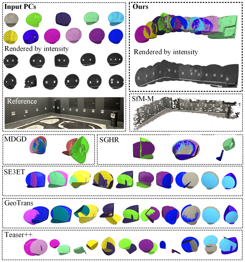
Summary. The dissertation develops an intensity-image-based LiDAR fiducial marker (IFM) system, extends marker localization from single scans to 3D maps, and proposes a two-level graph framework for registering unordered low-overlap multiview point clouds using thin-sheet markers. It also introduces the Livox-3DMatch dataset for training learning-based registration methods and reports experiments against MDGD, SGHR, SE3ET, GeoTrans, Teaser++, LOAM variants, KISS-ICP, and SfM-M across indoor/outdoor scenes, sparse-scan reconstruction, degraded scenes, GPS-denied localization, and large-scale map merging. The central claim is that this marker-based framework is robust to any unseen scenarios with extremely low overlap, providing a convenient, efficient, and low-cost mapping/localization tool.
Significance. The integrated system is a useful practical contribution: it transfers the convenience of visual fiducial markers to LiDAR point clouds, provides open-source implementations and datasets, and demonstrates large accuracy and runtime advantages over learning-based registration baselines in scenes instrumented with markers. The SVD-based pose estimation, the factor-graph MAP formulation, and the dataset-augmentation idea are each standard, but their combination is applied to a relevant and previously underexplored problem. The quantitative gains in the reported applications, such as the improvements to SGHR and MDGD from Livox-3DMatch (Table 4.4) and the low map-merging error in Table 4.7, are concrete and useful if the results are reproducible. The main weakness is that the headline robustness claim is broader than the algorithmic conditions and experimental protocol support.
major comments (3)
- [Section 4.1 and Section 4.2.3, Eq. (4.3)] The claim that the framework is "robust to any unseen scenarios with extremely low overlap" (Section 4.1, repeated in Section 4.4.3) is not supported by the algorithm as stated. In the first-level graph, a non-anchor scan receives an initial pose only if a path of co-observed markers connects it to the anchor scan; Eq. (4.3) requires a marker observed in both scans, and Dijkstra's algorithm operates over that co-visibility graph. A scan that sees no marker, or only markers not detected in any other scan, remains an isolated node and is never initialized, so the second-level graph cannot register it. None of the ten scenes in Table 4.2 or the applications in Sections 4.4.4-4.4.8 contains a disconnected or marker-free scan. The paper should either add experiments with disconnected marker co-visibility (for example, a scan with no detected markers, or a scan whose markers are observed by no other scan) or explicitly restrict the claim to scenes where the marker co-visibility graph is connected and every scan observes at least one marker.
- [Section 4.3 and Section 4.4.5] The Livox-3DMatch dataset is created using poses generated by the proposed marker-based pipeline itself, and no external ground truth (MoCap, RTK, or manually verified CAD alignment) is reported for the aligned 33 scans. The observed improvements to SGHR and MDGD on 3DMatch, ETH, and ScanNet are evidence that the added data are useful for training, but they do not establish the absolute accuracy of the generated poses. Since the dataset is presented as a training resource, the paper should either report a subset of held-out scans with independent pose ground truth or explicitly state that the poses inherit the accuracy of the proposed pipeline and cannot be treated as independently validated ground truth.
- [Sections 4.2.1, 3.2.3, and 4.2.4] Several free parameters that affect the reported results are not specified in the manuscript: the search scope S and step size δ in Algorithm 1, the OBB amplification factor t_b and the filtering thresholds in Section 3.2.3, and the noise covariance matrices Σ_k in Eq. (4.6), which are said to be determined by experiments in [39] without reporting the actual values. Without these settings, the quantitative results in Tables 4.2, 4.5, 4.6, and 4.7 cannot be reproduced from the text. Please provide the parameter values, and ideally a sensitivity analysis for the most important ones, or a clear statement that the open-source code contains the exact settings.
minor comments (4)
- [Throughout] There are several typographical issues: "T race" in Eq. (2.6) and nearby text should be "Trace"; "Apirltag" in Section 1.2.1 should be "AprilTag"; and "synthesis point cloud" in Section 3.2 should be "synthetic point cloud."
- [Section 4.2.1, Algorithm 1] In Algorithm 1, λ* is updated whenever Qtemp,l >= Ql, even if no new marker was appended to Q. This means the returned threshold is the last threshold with at least the current maximum number of detections, not necessarily the threshold at which the final marker set was first detected. Please clarify whether this is intentional and update the pseudocode or explanation.
- [Section 4.4.1] The ground-truth poses for the registration-accuracy experiments are obtained by manual alignment in CloudCompare. Given that the reported translation errors are often only a few centimeters, it would be helpful to quantify the precision of the manual ground truth, for example by cross-checking a subset of scenes against MoCap or RTK poses, or by reporting inter-annotator variability.
- [Table 3.1] The scene labels in Table 3.1 refer to figure panels ("Fig. 3.1(a)-Traj LO") rather than descriptive scene names. Using explicit scene names would make the table easier to read and compare.
Circularity Check
No significant circularity: the central mapping/localization claims are anchored to external ground truth, independent benchmarks, and code-released prior work.
full rationale
The derivation chain is self-contained in the relevant sense. Marker detection starts from raw LiDAR intensity values and known VFM pattern geometry, and pose estimation is a standard SVD least-squares alignment of detected 3D fiducials to predefined vertices; this is validated against OptiTrack MoCap ground truth (Section 2.5.1) and against LiDARTag on an external rosbag (Table 2.2). The multiview registration pipeline in Chapter 4 obtains initial relative poses from Eq. (4.3), which uses marker-pose measurements rather than any fitted target pose, and the second-level factor graph optimizes those same measurements with covariances taken from the author's previously published, open-source IFM work [39]. That self-citation is not load-bearing circularity because [39] is externally published, code-released, and does not encode the registration results being claimed. The Livox-3DMatch dataset is aligned using the proposed pipeline, but its value is demonstrated by improved benchmark performance of independent learning methods (Table 4.4), while the proposed method's own pose accuracy is separately checked against manually registered CloudCompare ground truth, MoCap, and RTK (Tables 4.2, 4.5, 4.6), so the reported success does not reduce to the method's own outputs. The 'any unseen scenarios' claim in Section 4.1 is broader than the tested regime because the first-level graph requires a path of co-observed markers to the anchor scan (Eq. 4.3), but that is an overgeneralization or scope limitation, not a circular derivation: no equation in the paper defines the claimed robustness in terms of the experimental outcome, and no fitted parameter is renamed as a prediction. I therefore find no step that can be quoted as reducing a claimed result to its own input by construction.
Assumptions & free parameters
free parameters (4)
- Adaptive threshold search parameters S and step size δ =
unspecified
- OBB buffer amplification factor t_b =
twice the marker side length
- OBB filtering thresholds =
SOBB in [a^2, 2a^2]; 1/1.5 <= l/w <= 1.5
- Noise covariance matrices Σ_k =
from experiments in [39]
assumptions (5)
- domain assumption Markers are planar thin sheets whose black-and-white patterns produce locally linear intensity gradients in LiDAR intensity images.
- domain assumption The spherical projection with Θa and Θi chosen from the LiDAR manual preserves enough pattern structure for VFM decoders after thresholding and blurring.
- domain assumption Every non-anchor scan is connected to the anchor scan through a path of co-observed markers in the first-level graph.
- standard math Standard SVD least-squares pose result uniqueness for coplanar non-collinear points applies and eliminates rotation ambiguity.
- domain assumption Ground truth poses obtained by manual alignment in CloudCompare are accurate enough for the error levels reported.
Cite this review
Pith. "Pith review of Mapping and Localization Using LiDAR Fiducial Markers." pith.science (2026). https://pith.science/paper/SSZHWCU2
@misc{pith2026250203510,
  author       = {Pith},
  title        = {Pith review of: Mapping and Localization Using LiDAR Fiducial Markers},
  year         = {2026},
  howpublished = {\url{https://pith.science/paper/SSZHWCU2}},
  note         = {Machine review of arXiv:2502.03510}
}
read the original abstract
LiDAR sensors are essential for autonomous systems, yet LiDAR fiducial markers (LFMs) lag behind visual fiducial markers (VFMs) in adoption and utility. Bridging this gap is vital for robotics and computer vision but challenging due to the sparse, unstructured nature of 3D LiDAR data and 2D-focused fiducial marker designs. This dissertation proposes a novel framework for mapping and localization using LFMs is proposed to benefit a variety of real-world applications, including the collection of 3D assets and training data for point cloud registration, 3D map merging, Augmented Reality (AR), and many more. First, an Intensity Image-based LiDAR Fiducial Marker (IFM) system is introduced, using thin, letter-sized markers compatible with VFMs. A detection method locates 3D fiducials from intensity images, enabling LiDAR pose estimation. Second, an enhanced algorithm extends detection to 3D maps, increasing marker range and facilitating tasks like 3D map merging. This method leverages both intensity and geometry, overcoming limitations of geometry-only detection approaches. Third, a new LFM-based mapping and localization method registers unordered, low-overlap point clouds. It employs adaptive threshold detection and a two-level graph framework to solve a maximum a-posteriori (MAP) problem, optimizing point cloud and marker poses. Additionally, the Livox-3DMatch dataset is introduced, improving learning-based multiview point cloud registration methods. Extensive experiments with various LiDAR models in diverse indoor and outdoor scenes demonstrate the effectiveness and superiority of the proposed framework.
Figures


Figures from the paper (42 more)




Reference graph
Works this paper leans on
-
[39]
Intensity image-based lidar fiducial marker system,
Y. Liu, H. Schofield, and J. Shan, “Intensity image-based lidar fiducial marker system,” IEEE Robotics and Automation Letters, vol. 7, no. 3, pp. 6542–6549, 2022
work page 2022
-
[1]
Flexible layouts for fiducial tags,
M. Krogius, A. Haggenmiller, and E. Olson, “Flexible layouts for fiducial tags,” in Proc. IEEE/RSJ International Conference on Intelligent Robots and Systems, 2019, pp. 1898–1903
2019
-
[2]
Matching distance and geometric dis- tribution aided learning multiview point cloud registration,
S. Li, J. Zhu, Y. Xie, N. Hu, and D. Wang, “Matching distance and geometric dis- tribution aided learning multiview point cloud registration,”IEEE Robotics and Au- tomation Letters, vol. 9, no. 11, pp. 9319–9326, 2024
2024
-
[3]
Robust multiview point cloud registration with reliable pose graph initialization and history reweighting,
H. Wang, Y. Liu, Z. Dong, Y. Guo, Y.-S. Liu, W. Wang, and B. Yang, “Robust multiview point cloud registration with reliable pose graph initialization and history reweighting,” inProc. of the IEEE/CVF Conference on Computer Vision and Pattern Recognition, 2023, pp. 9506–9515
2023
-
[4]
Se3et: Se(3)-equivariant transformer for low- overlap point cloud registration,
C. E. Lin, M. Zhu, and M. Ghaffari, “Se3et: Se(3)-equivariant transformer for low- overlap point cloud registration,” IEEE Robotics and Automation Letters, vol. 9, no. 11, pp. 9526–9533, 2024
2024
-
[5]
Geotransformer: Fast and robust point cloud registration with geometric transformer,
Z. Qin, H. Yu, C. Wang, Y. Guo, Y. Peng, S. Ilic, D. Hu, and K. Xu, “Geotransformer: Fast and robust point cloud registration with geometric transformer,”IEEE Trans- actions on Pattern Analysis and Machine Intelligence, vol. 45, no. 8, pp. 9806–9821, 2023. 115
2023
-
[6]
Teaser: Fast and certifiable point cloud registration,
H. Yang, J. Shi, and L. Carlone, “Teaser: Fast and certifiable point cloud registration,” IEEE Transactions on Robotics, vol. 37, no. 2, pp. 314–333, 2020
2020
-
[7]
An efficient visual sfm framework using planar markers,
Z. Jia, Y. Rao, H. Fan, and J. Dong, “An efficient visual sfm framework using planar markers,” IEEE Transactions on Instrumentation and Measurement, vol. 72, pp. 1–12, 2023
2023
Show all 96 references
-
[8]
KISS- ICP: In Defense of Point-to-Point ICP – Simple, Accurate, and Robust Registration If Done the Right Way,
I. Vizzo, T. Guadagnino, B. Mersch, L. Wiesmann, J. Behley, and C. Stachniss, “KISS- ICP: In Defense of Point-to-Point ICP – Simple, Accurate, and Robust Registration If Done the Right Way,”IEEE Robotics and Automation Letters, vol. 8, no. 2, pp. 1029–1036, 2023
2023
-
[9]
Lidartag: A real-time fiducial tag system for point clouds,
J.-K. Huang, S. Wang, M. Ghaffari, and J. W. Grizzle, “Lidartag: A real-time fiducial tag system for point clouds,”IEEE Robotics and Automation Letters, vol. 6, no. 3, pp. 4875–4882, 2021
2021
-
[10]
Traj-lo: In defense of lidar-only odometry using an effective continuous-time trajectory,
X. Zheng and J. Zhu, “Traj-lo: In defense of lidar-only odometry using an effective continuous-time trajectory,”IEEE Robotics and Automation Letters, vol. 9, no. 2, pp. 1961–1968, 2024
1961
-
[11]
A note on two problems in connexion with graphs,
E. W. Dijkstra, “A note on two problems in connexion with graphs,” inEdsger Wybe Dijkstra: His Life, Work, and Legacy, 2022, pp. 287–290
2022
-
[12]
Livox Mapping
Livox-SDK. Livox Mapping. (2020). [Online]. Available: https://github.com/ Livox-SDK/livox_mapping
2020
-
[13]
Loam livox: A fast, robust, high-precision lidar odometry and mapping package for lidars of small fov,
J. Lin and F. Zhang, “Loam livox: A fast, robust, high-precision lidar odometry and mapping package for lidars of small fov,” inProc. IEEE International Conference on Robotics and Automation, 2020, pp. 3126–3131. 116
2020
-
[14]
Loam: Lidar odometry and mapping in real-time
J. Zhang and S. Singh, “Loam: Lidar odometry and mapping in real-time.” inRobotics: Science and systems, vol. 2, no. 9. Berkeley, CA, 2014, pp. 1–9
2014
-
[15]
Rangedet: In defense of range view for lidar-based 3d object detection,
L. Fan, X. Xiong, F. Wang, N. Wang, and Z. Zhang, “Rangedet: In defense of range view for lidar-based 3d object detection,” inProc. IEEE/CVF International Confer- ence on Computer Vision, 2021
2021
-
[16]
Apriltag 2: Efficient and robust fiducial detection,
J. Wang and E. Olson, “Apriltag 2: Efficient and robust fiducial detection,” inProc. IEEE/RSJ International Conference on Intelligent Robots and Systems, 2016, pp. 4193–4198
2016
-
[17]
Apriltag: A robust and flexible visual fiducial system,
E. Olson, “Apriltag: A robust and flexible visual fiducial system,” in Proc. IEEE International Conference on Robotics and Automation, 2011, pp. 3400–3407
2011
-
[18]
Speeded up de- tection of squared fiducial markers,
F. J. Romero-Ramirez, R. Muñoz-Salinas, and R. Medina-Carnicer, “Speeded up de- tection of squared fiducial markers,”Image and vision Computing, vol. 76, pp. 38–47, 2018
2018
-
[19]
Detection and Accurate Lo- calization of Circular Fiducials under Highly Challenging Conditions,
L. Calvet, P. Gurdjos, C. Griwodz, and S. Gasparini, “Detection and Accurate Lo- calization of Circular Fiducials under Highly Challenging Conditions,” inProc. IEEE Conference on Computer Vision and Pattern Recognition, 2016, pp. 562 – 570
2016
-
[20]
A practical frame- work for the development of augmented reality applications by using aruco markers,
D. Avola, L. Cinque, G. L. Foresti, C. Mercuri, and D. Pannone, “A practical frame- work for the development of augmented reality applications by using aruco markers,” in Proc. International Conference on Pattern Recognition Applications and Methods, vol. 2, 2016, pp. 645–654
2016
-
[21]
Navigation of a self-driving vehicle using one fiducial marker,
Y. Liu, H. Schofield, and J. Shan, “Navigation of a self-driving vehicle using one fiducial marker,” inProc. IEEE International Conference on Multisensor Fusion and Integration for Intelligent Systems, 2021, pp. 1–6. 117
2021
-
[22]
Application of ghost-deblurgan to fiducial marker detection,
Y. Liu, A. Haridevan, H. Schofield, and J. Shan, “Application of ghost-deblurgan to fiducial marker detection,” inProc. IEEE/RSJ International Conference on Intelligent Robots and Systems, 2022, pp. 6827–6832
2022
-
[23]
Autonomous vision-based uav landing with collision avoidance using deep learning,
T. Liao, A. Haridevan, Y. Liu, and J. Shan, “Autonomous vision-based uav landing with collision avoidance using deep learning,” inScience and Information Conference. Springer, 2022, pp. 79–87
2022
-
[24]
Extending kalibr: Calibrating the extrinsics of multiple imus and of individual axes,
J. Rehder, J. Nikolic, T. Schneider, T. Hinzmann, and R. Siegwart, “Extending kalibr: Calibrating the extrinsics of multiple imus and of individual axes,” inProc. IEEE International Conference on Robotics and Automation, 2016, pp. 4304–4311
2016
-
[25]
Improvements to target-based 3d lidar to camera calibration,
J.-K. Huang and J. W. Grizzle, “Improvements to target-based 3d lidar to camera calibration,” IEEE Access, vol. 8, pp. 134101–134110, 2020
2020
-
[27]
Spm-slam: Simul- taneous localization and mapping with squared planar markers,
R. Muñoz-Salinas, M. J. Marin-Jimenez, and R. Medina-Carnicer, “Spm-slam: Simul- taneous localization and mapping with squared planar markers,”Pattern Recognition, vol. 86, pp. 156–171, 2019
2019
-
[28]
Variational bayesian estimator for mobile robot local- ization with unknown noise covariance,
S. Zhang, J. Shan, and Y. Liu, “Variational bayesian estimator for mobile robot local- ization with unknown noise covariance,”IEEE/ASME Transactions on Mechatronics, vol. 27, no. 4, pp. 2185–2193, 2022
2022
-
[29]
Particle filtering on lie group for mobile robot localization with range-bearing measurements,
——, “Particle filtering on lie group for mobile robot localization with range-bearing measurements,” IEEE Control Systems Letters, vol. 7, pp. 3753–3758, 2023. 118
2023
-
[30]
Multiway point cloud mosaicking with diffusion and global optimization,
S. Jin, I. Armeni, M. Pollefeys, and D. Barath, “Multiway point cloud mosaicking with diffusion and global optimization,” inProceedings of the IEEE/CVF Conference on Computer Vision and Pattern Recognition, 2024, pp. 20838–20849
2024
-
[31]
Approximate inference particle filtering for mobile robot slam,
S. Zhang, J. Shan, and Y. Liu, “Approximate inference particle filtering for mobile robot slam,” IEEE Transactions on Automation Science and Engineering, pp. 1–12, 2024
2024
-
[32]
Reconstructing objects in-the-wild for realistic sensor simulation,
Z. Yang, S. Manivasagam, Y. Chen, J. Wang, R. Hu, and R. Urtasun, “Reconstructing objects in-the-wild for realistic sensor simulation,” in Proc. of IEEE International Conference on Robotics and Automation, 2023, pp. 11661–11668
2023
-
[33]
Scalability in perception for autonomous driving: Waymo open dataset,
P. Sun, H. Kretzschmar, X. Dotiwalla, A. Chouard, V. Patnaik, P. Tsui, J. Guo, Y. Zhou, Y. Chai, B. Caineet al., “Scalability in perception for autonomous driving: Waymo open dataset,” inProc. of the IEEE/CVF conference on computer vision and pattern recognition, 2020, pp. 2446–2454
2020
-
[34]
Mv-deepsdf: Implicit modeling with multi-sweep point clouds for 3d vehicle reconstruction in autonomous driving,
Y. Liu, K. Zhu, G. Wu, Y. Ren, B. Liu, Y. Liu, and J. Shan, “Mv-deepsdf: Implicit modeling with multi-sweep point clouds for 3d vehicle reconstruction in autonomous driving,” in Proc. of the IEEE/CVF International Conference on Computer Vision, 2023, pp. 8306–8316
2023
-
[35]
3dmatch: Learning local geometric descriptors from rgb-d reconstructions,
A. Zeng, S. Song, M. Nießner, M. Fisher, J. Xiao, and T. Funkhouser, “3dmatch: Learning local geometric descriptors from rgb-d reconstructions,” inProc. of the IEEE conference on computer vision and pattern recognition, 2017, pp. 1802–1811
2017
-
[36]
Challenging data sets for point cloudregistrationalgorithms,
F. Pomerleau, M. Liu, F. Colas, and R. Siegwart, “Challenging data sets for point cloudregistrationalgorithms,” The International Journal of Robotics Research, vol.31, no. 14, pp. 1705–1711, 2012. 119
2012
-
[37]
Scannet: Richly-annotated 3d reconstructions of indoor scenes,
A. Dai, A. X. Chang, M. Savva, M. Halber, T. Funkhouser, and M. Nießner, “Scannet: Richly-annotated 3d reconstructions of indoor scenes,” in Proceedings of the IEEE conference on computer vision and pattern recognition, 2017, pp. 5828–5839
2017
-
[38]
Mending neural implicit modeling for 3d vehicle reconstruction in the wild,
S. Duggal, Z. Wang, W.-C. Ma, S. Manivasagam, J. Liang, S. Wang, and R. Urtasun, “Mending neural implicit modeling for 3d vehicle reconstruction in the wild,” inProc. of the IEEE/CVF Winter Conference on Applications of Computer Vision, 2022, pp. 1900–1909
2022
-
[40]
Mapping and localization from planar markers,
R. Muñoz-Salinas, M. J. Marín-Jimenez, E. Yeguas-Bolivar, and R. Medina-Carnicer, “Mapping and localization from planar markers,” Pattern Recognition, vol. 73, pp. 158–171, 2018
2018
-
[41]
Automatic extrinsic cali- bration method for lidar and camera sensor setups,
J. Beltrán, C. Guindel, A. de la Escalera, and F. García, “Automatic extrinsic cali- bration method for lidar and camera sensor setups,”IEEE Transactions on Intelligent Transportation Systems, vol. 23, no. 10, pp. 17677–17689, 2022
2022
-
[42]
Cpi: Lidar-camera extrinsic calibration based on feature points with reflection intensity,
L. Tao, L. Pei, T. Li, D. Zou, Q. Wu, and S. Xia, “Cpi: Lidar-camera extrinsic calibration based on feature points with reflection intensity,” in Spatial Data and Intelligence: First International Conference, SpatialDI 2020, Virtual Event, May 8–9, 2020, Proceedings 1. Springe...
2020
-
[43]
A4lidartag: Depth-based fiducial marker for extrinsic calibration of solid-state lidar and camera,
Y. Xie, L. Deng, T. Sun, Y. Fu, J. Li, X. Cui, H. Yin, S. Deng, J. Xiao, and B. Chen, “A4lidartag: Depth-based fiducial marker for extrinsic calibration of solid-state lidar and camera,” IEEE Robotics and Automation Letters, vol. 7, no. 3, pp. 6487–6494, 2022. 120
2022
-
[44]
Random sample consensus: a paradigm for model fitting with applications to image analysis and automated cartography,
M. A. Fischler and R. C. Bolles, “Random sample consensus: a paradigm for model fitting with applications to image analysis and automated cartography,”Communica- tions of the ACM, vol. 24, no. 6, pp. 381–395, 1981
1981
-
[45]
Predator: Regis- tration of 3d point clouds with low overlap,
S. Huang, Z. Gojcic, M. Usvyatsov, A. Wieser, and K. Schindler, “Predator: Regis- tration of 3d point clouds with low overlap,” inProc. of the IEEE/CVF Conference on Computer Vision and Pattern Recognition, June 2021, pp. 4267–4276
2021
-
[46]
Recognition of degradation scenarios for lidar slam applications,
C. Yang, Z. Chai, X. Yang, H. Zhuang, and M. Yang, “Recognition of degradation scenarios for lidar slam applications,” in Proc. IEEE International Conference on Robotics and Biomimetics. IEEE, 2022, pp. 1726–1731
2022
-
[47]
Structure-from-motion revisited,
J. L. Schonberger and J.-M. Frahm, “Structure-from-motion revisited,” inProceedings of the IEEE conference on computer vision and pattern recognition, 2016, pp. 4104– 4113
2016
-
[48]
Dust3r: Geometric 3d vision made easy,
S. Wang, V. Leroy, Y. Cabon, B. Chidlovskii, and J. Revaud, “Dust3r: Geometric 3d vision made easy,” inProceedings of the IEEE/CVF Conference on Computer Vision and Pattern Recognition, 2024, pp. 20697–20709
2024
-
[49]
Omniobject3d: Large-vocabulary 3d object dataset for realistic per- ception, reconstruction and generation,
T. Wu, J. Zhang, X. Fu, Y. Wang, J. Ren, L. Pan, W. Wu, L. Yang, J. Wang, C. Qianet al., “Omniobject3d: Large-vocabulary 3d object dataset for realistic per- ception, reconstruction and generation,” inProceedings of the IEEE/CVF Conference on Computer Vision and Pattern Recogn...
2023
-
[50]
Arc-support line segments revisited: An efficient high-quality ellipse detection,
C. Lu, S. Xia, M. Shao, and Y. Fu, “Arc-support line segments revisited: An efficient high-quality ellipse detection,”IEEE Transactions on Image Processing, vol. 29, pp. 768–781, 2019. 121
2019
-
[51]
Circle detection by arc-support line segments,
C. Lu, S. Xia, W. Huang, M. Shao, and Y. Fu, “Circle detection by arc-support line segments,” in Proc. IEEE International Conference on Image Processing, 2017, pp. 76–80
2017
-
[52]
Infinitesimal plane-based pose estimation,
T. Collins and A. Bartoli, “Infinitesimal plane-based pose estimation,”International journal of computer vision, vol. 109, no. 3, pp. 252–286, 2014
2014
-
[53]
Navigation of a self-driving vehicle using one fiducial marker,
Y. Liu, H. Schofield, and J. Shan, “Navigation of a self-driving vehicle using one fiducial marker,” inProc. IEEE International Conference on Multisensor Fusion and Integration for Intelligent Systems, 2021, pp. 1–6
2021
-
[54]
Resolving marker pose ambiguity by robust rotation averaging with clique constraints,
S.-F. Ch’ng, N. Sogi, P. Purkait, T.-J. Chin, and K. Fukui, “Resolving marker pose ambiguity by robust rotation averaging with clique constraints,” inProc. IEEE Inter- national Conference on Robotics and Automation, 2020, pp. 9680–9686
2020
-
[55]
Accurate outdoor ground truth based on total stations,
M. Vaidis, P. Giguère, F. Pomerleau, and V. Kubelka, “Accurate outdoor ground truth based on total stations,” in2021 18th Conference on Robots and Vision (CRV), 2021, pp. 1–8
2021
-
[56]
Unified temporal and spatial calibration for multi-sensor systems,
P. Furgale, J. Rehder, and R. Siegwart, “Unified temporal and spatial calibration for multi-sensor systems,” in Porc. IEEE/RSJ International Conference on Intelligent Robots and Systems, 2013, pp. 1280–1286
2013
-
[57]
Fast range image segmentation by an edge detection strategy,
A. D. Sappa and M. Devy, “Fast range image segmentation by an edge detection strategy,” in Proc. International Conference on 3-D Digital Imaging and Modeling, 2001, pp. 292–299
2001
-
[58]
Hierarchical clustering schemes,
S. C. Johnson, “Hierarchical clustering schemes,”Psychometrika, vol. 32, no. 3, pp. 241–254, 1967. 122
1967
-
[59]
F-loam: Fast lidar odometry and map- ping,
H. Wang, C. Wang, C.-L. Chen, and L. Xie, “F-loam: Fast lidar odometry and map- ping,” in2021 IEEE/RSJ International Conference on Intelligent Robots and Systems (IROS). IEEE, 2021, pp. 4390–4396
2021
-
[60]
Tong and C
Q. Tong and C. Shaozu. A-LOAM: Advanced implementation of loam. (2019). [Online]. Available: âĂİhttps://github.com/HKUST-Aerial-Robotics/A-LOAM
2019
-
[61]
Learning multiview 3d point cloud registration,
Z. Gojcic, C. Zhou, J. D. Wegner, L. J. Guibas, and T. Birdal, “Learning multiview 3d point cloud registration,” inProc. of the IEEE/CVF conference on computer vision and pattern recognition, 2020, pp. 1759–1769
2020
-
[62]
Learning compact geometric features,
M. Khoury, Q.-Y. Zhou, and V. Koltun, “Learning compact geometric features,” in Proc. of the IEEE international conference on computer vision, 2017, pp. 153–161
2017
-
[63]
Improvements to thin-sheet 3d lidar fiducial tag localization,
Y. Liu, J. Shan, and H. Schofield, “Improvements to thin-sheet 3d lidar fiducial tag localization,” IEEE Access, vol. 12, pp. 124907–124914, 2024
2024
-
[64]
L-pr: Exploiting lidar fiducial marker for unordered low overlap multiview point cloud registration,
Y. Liu, J. Shan, A. Haridevan, and S. Zhang, “L-pr: Exploiting lidar fiducial marker for unordered low overlap multiview point cloud registration,”IEEE Transactions on Instrumentation and Measurement, 2025
2025
-
[65]
T. D. Barfoot,State estimation for robotics. Cambridge University Press, 2017
2017
-
[66]
Tagslam: Robust slam with fiducial markers,
B. Pfrommer and K. Daniilidis, “Tagslam: Robust slam with fiducial markers,”arXiv preprint arXiv:1910.00679, 2019
1910 arXiv
-
[67]
Lasernet: An efficient probabilistic 3d object detector for autonomous driving,
G. P. Meyer, A. Laddha, E. Kee, C. Vallespi-Gonzalez, and C. K. Wellington, “Lasernet: An efficient probabilistic 3d object detector for autonomous driving,” in Proc. IEEE/CVF Conference on Computer Vision and Pattern Recognition, 2019, pp. 12677–12686. 123
2019
-
[68]
Good colour maps: How to design them,
P. Kovesi, “Good colour maps: How to design them,”arXiv preprint arXiv:1509.03700, 2015
2015 arXiv
-
[69]
3d is here: Point cloud library (pcl),
R. B. Rusu and S. Cousins, “3d is here: Point cloud library (pcl),” inProc. IEEE International Conference on Robotics and Automation, 2011, pp. 1–4
2011
-
[70]
A class of fast gaussian binomial filters for speech and image processing,
R. A. Haddad, A. N. Akansuet al., “A class of fast gaussian binomial filters for speech and image processing,” IEEE Transactions on Signal Processing, vol. 39, no. 3, pp. 723–727, 1991
1991
-
[71]
Nicp: Dense normal based point cloud registration,
J. Serafin and G. Grisetti, “Nicp: Dense normal based point cloud registration,” in Proc. IEEE/RSJ International Conference on Intelligent Robots and Systems, 2015, pp. 742–749
2015
-
[72]
Least-squares fitting of two 3-d point sets,
K. S. Arun, T. S. Huang, and S. D. Blostein, “Least-squares fitting of two 3-d point sets,” IEEE Transactions on pattern analysis and machine intelligence, no. 5, pp. 698–700, 1987
1987
-
[73]
Scalable fiducial tag localization on a 3d prior map via graph-theoretic global tag-map registration,
K. Koide, S. Oishi, M. Yokozuka, and A. Banno, “Scalable fiducial tag localization on a 3d prior map via graph-theoretic global tag-map registration,” inProc. of IEEE/RSJ International Conference on Intelligent Robots and Systems. IEEE, 2022, pp. 5347– 5353
2022
-
[74]
Vins-mono: A robust and versatile monocular visual- inertial state estimator,
T. Qin, P. Li, and S. Shen, “Vins-mono: A robust and versatile monocular visual- inertial state estimator,”IEEE transactions on robotics, vol. 34, no. 4, pp. 1004–1020, 2018
2018
-
[75]
Semantic 3d object maps for everyday manipulation in human living environments,
R. B. Rusu, “Semantic 3d object maps for everyday manipulation in human living environments,” KI-Künstliche Intelligenz, vol. 24, no. 4, pp. 345–348, 2010
2010
-
[76]
Schneider and D
P. Schneider and D. H. Eberly,Geometric tools for computer graphics. Elsevier, 2002. 124
2002
-
[77]
Cloudcompare,
D. Girardeau-Montautet al., “Cloudcompare,”France: EDF R&D Telecom ParisTech, vol. 11, no. 5, 2016
2016
-
[78]
isam2: In- cremental smoothing and mapping with fluid relinearization and incremental variable reordering,
M. Kaess, H. Johannsson, R. Roberts, V. Ila, J. Leonard, and F. Dellaert, “isam2: In- cremental smoothing and mapping with fluid relinearization and incremental variable reordering,” inProc. of IEEE International Conference on Robotics and Automation, 2011, pp. 3281–3288
2011
-
[79]
Dellaert and M
F. Dellaert and M. Kaess, Factor Graphs for Robot Perception. Foundations and Trends in Robotics, Vol. 6, 2017. [Online]. Available: http://www.cs.cmu.edu/ ~kaess/pub/Dellaert17fnt.pdf
2017
-
[80]
Supervisely Computer Vision platform
Supervisely. Supervisely Computer Vision platform. (2023). [Online]. Available: https://supervisely.com
2023
-
[81]
Fiducial tag localization on a 3d lidar prior map,
Y. Liu, J. Shan, and H. Schofield, “Fiducial tag localization on a 3d lidar prior map,”
-
[82]
Unsupervised intrinsic image decomposition with lidar intensity,
S. Sato, Y. Yao, T. Yoshida, T. Kaneko, S. Ando, and J. Shimamura, “Unsupervised intrinsic image decomposition with lidar intensity,” inProceedings of the IEEE/CVF Conference on Computer Vision and Pattern Recognition, 2023, pp. 13466–13475
2023
-
[83]
Neural lidar fields for novel view synthesis,
S. Huang, Z. Gojcic, Z. Wang, F. Williams, Y. Kasten, S. Fidler, K. Schindler, and O. Litany, “Neural lidar fields for novel view synthesis,” inProceedings of the IEEE/CVF International Conference on Computer Vision, 2023, pp. 18236–18246
2023
-
[84]
Lidar4d: Dynamic neural fields for novel space-time view lidar synthesis,
Z. Zheng, F. Lu, W. Xue, G. Chen, and C. Jiang, “Lidar4d: Dynamic neural fields for novel space-time view lidar synthesis,” inProceedings of the IEEE/CVF Conference on Computer Vision and Pattern Recognition, 2024, pp. 5145–5154. 125 List of Publications
2024
-
[86]
Navigation of a Self-Driving Vehicle Using One Fiducial Marker,
Y. Liu, H. Schofield and J. Shan, "Navigation of a Self-Driving Vehicle Using One Fiducial Marker," IEEE International Conference on Multisensor Fusion and Inte- gration for Intelligent Systems (MFI), Karlsruhe, Germany, 2021, pp. 1-6, DOI: 10.1109/MFI52462.2021.9591194
2021
-
[87]
Intensity Image-Based LiDAR Fiducial Marker System,
Y. Liu, H. Schofield and J. Shan, "Intensity Image-Based LiDAR Fiducial Marker System," in IEEE Robotics and Automation Letters (RA-L), vol. 7, no. 3, pp. 6542-6549, 2022, DOI:10.1109/LRA.2022.3174971
2022
-
[88]
Application of Ghost-DeblurGAN to Fiducial Marker Detection,
Y. Liu, A. Haridevan, H. Schofield and J. Shan, "Application of Ghost-DeblurGAN to Fiducial Marker Detection," IEEE/RSJ International Conference on Intelligent Robots and Systems (IROS), Kyoto, Japan, 2022, pp. 6827-6832, DOI:10.1109/ IROS47612.2022.9981701
2022
-
[89]
MV-DeepSDF: Implicit Modeling with Multi-Sweep Point Clouds for 3D Vehicle Reconstruction in Autonomous Driving,
Y. Liu , K. Zhu, G. Wu. Y. Ren, B. Liu, Y. Liu, and J. Shan, "MV-DeepSDF: Implicit Modeling with Multi-Sweep Point Clouds for 3D Vehicle Reconstruction in Autonomous Driving," IEEE/CVF International Conference on Computer Vi- sion (ICCV), Paris, France, 2023, pp. 8272-8282, DO...
2023
-
[90]
VQA-Diff: 126 ExploitingVQAandDiffusionforZero-ShotImage-to-3DVehicleAssetGenerationin Autonomous Driving,
Y. Liu*, Z. Yang*, G. Wu. Y. Ren, K. Lin, B. Liu, Y. Liu, and J. Shan, "VQA-Diff: 126 ExploitingVQAandDiffusionforZero-ShotImage-to-3DVehicleAssetGenerationin Autonomous Driving," European Conference on Computer Vision (ECCV), Milan, Italy, 2024. pp. 323-340, DOI:https://doi.o...
2024 doi
-
[91]
Improvements to Thin-Sheet 3D LiDAR Fiducial Tag Localization,
Y. Liu, J. Shan, and H. Schofield, "Improvements to Thin-Sheet 3D LiDAR Fiducial Tag Localization,", IEEE ACCESS, vol. 12, pp. 124907-124914, 2024, DOI:10. 1109/ACCESS.2024.3451404
2024
-
[92]
L-PR: Exploiting LiDAR Fidu- cial Marker for Unordered Low Overlap Multiview Point Cloud Registration,
Y. Liu , J. Shan, A. Haridevan, and S. Zhang, “L-PR: Exploiting LiDAR Fidu- cial Marker for Unordered Low Overlap Multiview Point Cloud Registration,” IEEE Transactions on Instrumentation & Measurement (TIM), in press, 2025
2025
-
[93]
Approximate Inference Particle Filtering for Mobile Robot SLAM,
S. Zhang, J. Shan, andY. Liu, "Approximate Inference Particle Filtering for Mobile Robot SLAM," in IEEE Transactions on Automation Science and Engineering (T- ASE), pp. 1-12, 2024, DOI:10.1109/TASE.2024.3475735
2024
-
[94]
Learning Effective NeRFs and SDFs Representations with 3D GANs for Object Generation,
Z. Yang*,Y. Liu*, G. Wu, T. Cao, Y. Ren, Y. Liu, and B. Liu, “Learning Effective NeRFs and SDFs Representations with 3D GANs for Object Generation,”NeurIPS W orkshop, 2024 (* co-first author)
2024
-
[95]
Variational Bayesian Estimator for Mobile Robot Localization With Unknown Noise Covariance,
S. Zhang, J. Shan, andY. Liu, "Variational Bayesian Estimator for Mobile Robot Localization With Unknown Noise Covariance," in IEEE/ASME Transactions on Mechatronics (T-MECH), vol. 27, no. 4, pp. 2185-2193, 2022, DOI: 10.1109/ TMECH.2022.3161591
2022
-
[96]
Particle Filtering on Lie Group for Mobile Robot Localization With Range-Bearing Measurements,
S. Zhang, J. Shan, andY. Liu, "Particle Filtering on Lie Group for Mobile Robot Localization With Range-Bearing Measurements," in IEEE Control Systems Letters (L-CSS), vol. 7, pp. 3753-3758, 2023, DOI:10.1109/LCSYS.2023.3340419. 127
2023
-
[97]
Autonomous Vision-Based UAV Land- ing with Collision Avoidance Using Deep Learning,
T. Liao, A. Haridevan,Y. Liu, and J. Shan, “Autonomous Vision-Based UAV Land- ing with Collision Avoidance Using Deep Learning,” Science and Information Con- ference (SAI), pp. 79–87, 2022, DOI:10.1007/978-3-031-10464-0_6 128
2022 doi
-
[2024]
Available: https://arxiv.org/abs/2209.01072
[Online]. Available: https://arxiv.org/abs/2209.01072
Reviewed August 9, 2026 · model on record in the stance chip above.
Discussion (0). Continue with ORCID to comment.