REVIEW 3 major objections 5 minor 24 references
Towards a quantum realization of the ampere using single-electron resolution Skipper-CCDs
T0 review · 3 major / 5 minor · reviewed 2026-08-08 · deepseek-v4-flash
Pith's one-line read A standard Skipper-CCD can act as a self-referenced electron-pump current source, producing currents from femtoamperes to about 1 nA that agree with an external electrometer.
desk verdict A genuine new proof-of-concept for Skipper-CCD current sources, but the central compatibility check needs an independent calibration or transfer-loss test before the quantitative claim holds. read the letter →
The pith
A machine-rendered reading of the paper's core claim, the machinery that carries it, and where it could break.
The reading
What carries the argument
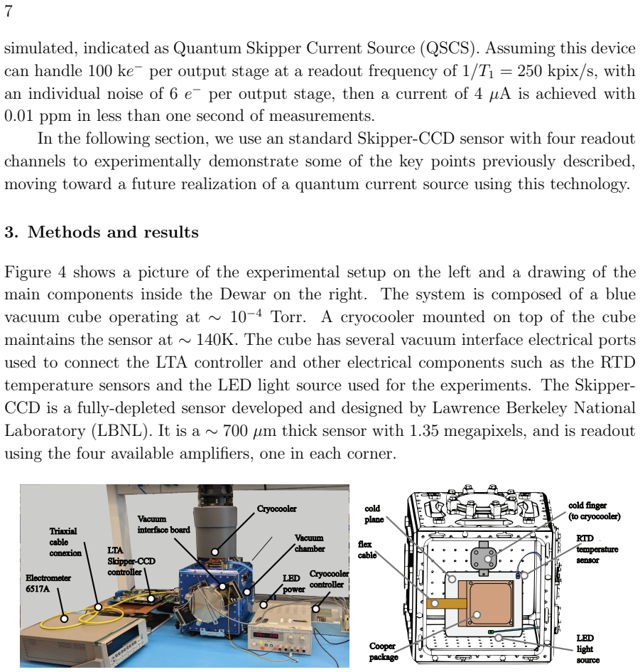
The central object is the Skipper-CCD output stage: a floating-gate sense node that measures a charge packet capacitively and non-destructively, a reset transistor, and a dump gate that drains the measured charge to an external terminal. Because the same packet can be sampled repeatedly, the sensor reaches sub-electron noise and resolves individual electron peaks; those peaks provide an absolute ADU-to-electron calibration without external standards. The drain terminal is connected to an electrometer to cross-check the self-measured charge, and the timing schemes used in the experiments—constant packet rate, larger packets, or packet-dependent drain delays—convert measured charge packets into a current of the form $I = N f e^{-}$.
What would settle it
A direct measurement of charge transfer efficiency across the dump gate would settle the central claim: count a known single-electron packet at the sense node, drain it, and count what arrives at the electrometer; if the drained count is systematically less than the measured packet, the self-referenced current source does not deliver the current it claims.
Extended reading notes
Core claim
The central claim is that a standard Skipper-CCD can perform every core function of a self-referenced electron-pump current source: absolute calibration from resolved single-electron peaks, non-destructive measurement of each charge packet, controlled draining of packets at adjustable rates, and generation of currents spanning femtoamperes to about 1 nA that agree with an external electrometer after a disclosed linear correction (slope 1.026). The authors state the objective is to explore the potential of the technology, and they are explicit that the demonstrated device is not yet a metrological realization of the ampere.
Load-bearing premise
The load-bearing premise is that charge transfer and draining are lossless and complete: every electron the sense node measures non-destructively is later moved over the dump gate and reaches the external drain and electrometer with no trapping, recombination, or sub-threshold leakage, and the paper does not present a direct measurement of this transfer efficiency.
Editorial extensions
If this is right
- The demonstrated agreement between drained charge and electrometer readings means the sensor can serve as its own charge meter while generating current, removing the need for a separate calibration source in the current path.
- With row binning and faster pixel rates, a single Skipper-CCD can reach currents around 1 nA without gigahertz clocking; the paper's projections show that parallel operation of many sensors could reach microampere-level currents with ppm-level precision over measurement times of seconds to minutes.
- In single-electron resolution mode, the sensor produces discrete current levels with steps of one electron charge, showing that the same device can span femtoampere and nanoampere regimes.
- By adjusting the drain delay for each measured charge packet, the sensor can generate arbitrary current waveforms, demonstrated for a constant current and a triangular current.
- The scaling path to a practical ampere realization goes through faster readout electronics, larger full-well capacity, and new Skipper sensors with multiple amplifiers per pixel, all of which the paper identifies as feasible extensions.
Reading between the lines
- Editorial inference: If a dedicated charge-transfer-efficiency measurement showed that every electron measured at the sense node also reaches the drain, the Skipper-CCD could advance from a transfer standard toward a primary realization of the ampere; the paper stops short of that end-to-end uncertainty budget.
- Editorial inference: The self-calibration property could remove one of the main scaling obstacles for parallel electron pumps: each output stage can calibrate its own gain, relaxing the device-matching requirements that limit multi-pump arrays.
- Editorial inference: The per-packet timing control demonstrated for arbitrary waveforms suggests a closed-loop current source in which the measured charge of each packet sets the next drain delay; such online feedback is within reach of the existing firmware-based readout.
- Editorial inference: If Skipper-in-CMOS sensors with per-pixel amplifiers mature, the same self-referencing principle could operate at higher temperatures, extending single-electron current generation well beyond the cryogenic niche of existing electron pumps.
Editorial analysis
A structured set of objections, weighed in public.
Referee Report
Summary. The paper proposes using Skipper-CCDs as self-referenced electron-pump current sources for a practical realization of the ampere. It describes the sensor architecture, presents theoretical ppm scaling for various CCD configurations, and reports four experiments: absolute calibration from single-electron peak spacing (Section 3.1), comparison of CCD self-measured charge with a Keithley 6517A electrometer for different exposures (Section 3.2), a fast-readout experiment claiming up to ~1 nA from a single sensor (Section 3.3), discrete fA-level current generation with quantum steps (Section 3.4), and arbitrary current waveform generation by per-pixel delay control (Section 3.5). The central claim is that the Skipper-CCD can self-calibrate over a wide charge range and that its self-measured charge is compatible with an external electrometer after a linear correction of slope m=1.026.
Significance. If the charge-delivery path were independently established, this would be a valuable proof-of-concept for CCD-based current sources, with an attractive combination of wide dynamic range, self-calibration, and operation near 140 K. The paper deserves credit for the clean absolute calibration anchored to the zero-electron peak and single-electron spacing, for the zero-exposure control showing near-zero CCD variance, and for honestly labeling the work as a proof of concept rather than a metrological realization. However, the unresolved ambiguity between electrometer gain error and possible CCD charge loss during transfer/dump prevents the data from quantitatively supporting the stronger 'self-referenced current source' interpretation.
major comments (3)
- [§3.2.2, Table 1, and §4] The central compatibility claim rests on a linear correction m=1.026 that is fitted to the same dataset used to demonstrate agreement. Because §3.2.2 explicitly assumes that no measuring or processing error is associated with the CCD data, the observed 2.6% systematic difference is equally consistent with a 2.6% loss of charge during horizontal transfer, dump-gate operation, or drain-path leakage before reaching the electrometer. The text attributes the discrepancy to an uncalibrated electrometer gain and to post-processing drift, but no independent electrometer calibration or charge-transfer-efficiency measurement is reported. The paper's own caveats in §4 (uncalibrated electrometer, known drain leakage) do not resolve the degeneracy between instrument gain error and CCD charge loss, so the claimed equivalence between self-measured charge and delivered current is not quantitatively established.
- [§3.2.2, error propagation formula] The expression e_Δ,μ = sqrt(σ_elec²/N_cap − σ_CCD²/N_cap) is derived under the premise that the CCD has zero measurement and processing error. The zero-exposure row in Table 1 supports low CCD readout noise, but it does not justify neglecting systematic gain or transfer errors; those errors are exactly what the fitted slope m=1.026 is meant to correct. Consequently, the uncertainty estimate for the mean difference omits the dominant systematic term, and the statement that the corrected mean is 'compatible with the errors presented in the table' is based on an underestimate of the relevant uncertainty.
- [§3.3] The claim that a single sensor achieves currents up to 1 nA is obtained from I=Q/t_CCD, where Q is the charge self-measured by the CCD. Given the unresolved scale ambiguity between CCD-reported charge and actually drained charge identified in Section 3.2, the magnitude of the delivered current inherits the same possible 2.6% systematic offset. The experiment thus demonstrates the capability to self-measure large packets quickly, but the external electrometer comparison in this section is subject to the same fitted-correction limitation and does not independently confirm the delivered current.
minor comments (5)
- [Section heading after §5] The word 'Ackkowledgments' is a typo and should read 'Acknowledgments'.
- [§3.2.1] The conversion factor is stated as 1 e− = 1.60217646 × 10⁻¹⁹ C; the correct 2019 SI value is 1.602176634 × 10⁻¹⁹ C. This is a small but relevant detail for a paper aimed at the ampere realization.
- [Figure 7] The caption does not explain that the first flat interval includes the exposure time plus instrument initialization; adding this would make the timeline easier to follow.
- [§2.1, Eq. (1) and (2)] The derivation of ppm is clear, but the text does not explicitly state that the timing period T1 is assumed to be exactly known (perfect timing); adding that assumption would make the idealized nature of the ppm curves explicit.
- [§3.4] The text says a row binning of 20000 was employed but later uses T=14.74 ms as the pixel acquisition time for the current conversion; please clarify whether T includes the full readout and reset sequence or only the expose/drain period.
Circularity Check
Electrometer compatibility partially reduces to a fitted correction: the m=1.026 slope is fit to the same CCD-versus-electrometer data that is then declared consistent, while the sensor self-calibration itself remains non-circular.
-
fitted input called prediction
[Section 4 (Discussion), after Table 1; applied to Section 3.2.2 data]
"A linear regression to quantify this systematic offset was performed between the mean of both instruments, yielding a coefficient of determination (R2) very close to one (0.9998)... The slope obtained for the linear regression, m = 1.026, was used as a correction: µ∗diff = µelec/m − µCCD, and added as the last column in table 1. This corrected mean is compatible with the errors presented in the table."
The slope m is estimated from the same μ_elec versus μ_CCD means that are then declared compatible after rescaling by 1/m. Least-squares fitting guarantees the residuals μ_elec/m − μ_CCD are centered near zero, so the statement that the corrected mean is 'compatible' is a restatement of the fit, not an independent check. The paper also assumes 'no measuring nor processing error is associated to the CCD data' when assigning uncertainty, so a ~2.6% CCD charge loss during transfer or dump would be absorbed into m and misattributed to electrometer gain. Thus the electrometer comparison does not independently establish that self-measured charge equals drained charge; it only shows the data can be made consistent with a fitted gain.
full rationale
The paper's strongest non-circular element is Section 3.1: the absolute calibration is anchored to the zero-electron peak and the single-electron peak spacing of the Skipper-CCD, so the ADU-to-electron conversion is not fitted to the electrometer. The circular issue is confined to the electrometer comparison of Section 3.2/4. There, the systematic 2.6% slope between μ_elec and μ_CCD is estimated from the same six exposure points, and then μ_elec/m − μ_CCD is reported as 'compatible.' Because m is a least-squares fit on those same points, the corrected residuals are near zero by construction; this is an in-sample consistency check rather than an independent validation that the charge measured by the sense node equals the charge actually drained to the electrometer. The paper's own error formula assumes no CCD measurement or processing error, and the electrometer is acknowledged to be uncalibrated, so the slope could equally be explained by ~2.6% charge loss in horizontal transfer, dump, or drain path. Section 3.3 inherits this ambiguity when it uses Q/t_CCD as the current and cites electrometer compatibility as support. The self-citations to prior Skipper-CCD noise and parallel-readout work are used only for theoretical ppm projections and are not load-bearing for the experimental demonstration. Overall, the central self-calibration and discrete-electron demonstrations are independent; only the 'compatibility' claim is partially circular, so the score is 4 rather than higher.
Assumptions & free parameters
free parameters (2)
- Electrometer gain correction slope m =
1.026
- Electrometer leakage current fit =
approximately 10 pA
assumptions (5)
- domain assumption Photon arrivals follow Poisson statistics and exposures are independent.
- domain assumption Skipper-CCD measurement and processing error is negligible compared with photon statistics, so sigma_CCD is approximately sigma_light.
- domain assumption Charge transfer from sense node to drain is lossless and complete.
- domain assumption Electrometer leakage is constant during each capture and can be removed by a linear fit.
- domain assumption Readout timing is exact: the pixel period T0 or T1 accurately defines the current I = Q/T.
invented entities (1)
-
Quantum Skipper Current Source (QSCS) hypothetical 1000-stage device
Cite this review
Pith. "Pith review of Towards a quantum realization of the ampere using single-electron resolution Skipper-CCDs." pith.science (2026). https://pith.science/paper/SPJXTY4Z
@misc{pith2026250207742,
  author       = {Pith},
  title        = {Pith review of: Towards a quantum realization of the ampere using single-electron resolution Skipper-CCDs},
  year         = {2026},
  howpublished = {\url{https://pith.science/paper/SPJXTY4Z}},
  note         = {Machine review of arXiv:2502.07742}
}
read the original abstract
This paper presents a proof-of-concept demonstration of the Skipper-CCD, a sensor with single-electron counting capability, as a promising technology for implementing an electron-pump-based current source. Relying on its single-electron resolution and built-in charge sensing, it allows self-calibration of the charge packets. This article presents an initial discussion of how low ppm and high current realizations can be achieved with this technology. We report experimental results that illustrate the key functionalities in manipulating both small and large electron charge packets, including a comparison of the charge generated, self-measured, and drained by the sensor against measurements from an electrometer. These results were obtained using a standard sensor and readout electronics without specific optimizations for this application. The objective is to explore the potential of Skipper-CCD for realizing an electron-based current source.
Figures


Figures from the paper (8 more)


Reference graph
Works this paper leans on
-
[1]
Bureau International des Poids et Mesures (BIPM) 2019 BIPM Publications 1–220 URL https://www.bipm.org/en/publications/si-brochure
work page 2019
-
[2]
Pekola J P, Saira O P, Maisi V F, Kemppinen A, M¨ ott¨ onen M, Pashk in Y A and Averin D V 2013 Rev. Mod. Phys. 85(4) 1421–1472 URL https://link.aps.org/doi/10.1103/RevModPhys.85.1421
-
[3]
Pekola J P, Vartiainen J J, M¨ ott¨ onen M, Saira O P, Meschke M and Averin D V 2008 Nature Physics 4 120–124 ISSN 1745-2481 URL https://doi.org/10.1038/nphys808
-
[4]
Averin D V and Pekola J P 2008 Phys. Rev. Lett. 101(6) 066801 URL https://link.aps.org/doi/10.1103/PhysRevLett.101.066801
-
[5]
Shilton J M, Talyanskii V I, Pepper M, Ritchie D A, Frost J E F, Ford C J B, Smith C G and Jones G A C 1996 Journal of Physics: Condensed Matter 8 L531 URL https://dx.doi.org/10.1088/0953-8984/8/38/001
-
[6]
Giblin S, Kataoka M, Fletcher J, See P, Janssen T, Griffiths J, Jone s G, Farrer I and Ritchie D 2012 Nature communications 3 1–6
work page 2012
-
[7]
Giblin S P, Mykk¨ anen E, Kemppinen A, Immonen P, Manninen A, Jene i M, M¨ ott¨ onen M, Yamahata G, Fujiwara A and Kataoka M 2020 Metrologia 57 025013
work page 2020
-
[8]
Yamahata G, Giblin S P, Kataoka M, Karasawa T and Fujiwara A 2017 Scientific Reports 7 45137
work page 2017
Show all 24 references
-
[9]
Brun-Picard J, Djordjevic S, Leprat D, Schopfer F and Poirier W 2016 Phys. Rev. X 6(4) 041051 URL https://link.aps.org/doi/10.1103/PhysRevX.6.041051
2016 doi
-
[10]
Cheung K P, Wang C and Campbell J P 2020 Micromachines 11 364
2020
-
[11]
Cheung K P and O’Sullivan B J 2023 Applied Physics Letters 122 184001 ISSN 0003-6951 URL https://doi.org/10.1063/5.0146398
2023 doi
-
[12]
Fricke L, Wulf M, Kaestner B, Hohls F, Mirovsky P, Mackrodt B, D olata R, Weimann T, Pierz K, Siegner U and Schumacher H W 2014 Phys. Rev. Lett. 112(22) 226803 URL https://link.aps.org/doi/10.1103/PhysRevLett.112.226803
2014 doi
-
[13]
Norimoto S, See P, Schoinas N, Rungger I, Boykin T, Stewart M, Griffiths J, Chen C, Ritchie D and Kataoka M 2024 Applied Physics Letters 125
2024
-
[14]
Nakamura S, Matsumaru D, Yamahata G, Oe T, Chae D H, Okazak i Y, Takada S, Maruyama M, Fujiwara A and Kaneko N H 2024 Nano Letters 24 9–15
2024
-
[15]
Chierchie F, Chavez C, Haro M S, Moroni G F, Cervantes-Verga ra B, Perez S, Estrada J, Tiffenberg J, Uemura S and Botti A 2023 Journal of Instrumentation 18 P01040
2023
-
[16]
Cervantes-Vergara B A, Perez S, Estrada J, Botti A, Chave z C R, Chierchie F, Saffold N, Aguilar- Arevalo A, Alcalde-Bessia F, Avalos N, Baez O, Baxter D, Bertou X, B onifazi C, Cancelo G, Castell´ o-Mor N, Chavarria A E, Egea J M D, D’Olivo J C, Dreyer C, Drlica -Wagner A, Ess...
2023
-
[17]
Botti A M, Cervantes-Vergara B A, Chavez C R, Chierchie F, Dr lica-Wagner A, Estrada J, Moroni 18 G F, Holland S E, Gimenez B I, Lapi A J, Villalpando E M, Haro M S, Tiffenber g J and Uemura S 2024 IEEE Transactions on Electron Devices 71 3732–3738
2024
-
[18]
Lapi A J, Gimenez B J I, Gamero M E, Blanco C R C, Chierchie F, Fern andez- Moroni G, Holland S, Botti A M, Cervantes-Vergara B A, Tiffenberg J and Estrada J 2024 Journal of Astronomical Telescopes, Instruments, and Syst ems 11 011203 URL https://doi.org/10.1117/1.JATIS.11.1.011203
2024 doi
-
[19]
Lapi A J, Sofo-Haro M, Parpillon B C, Birman A, Fernandez-Moro ni G, Rota L, Bessia F A, Gupta A, Blanco C R C, Chierchie F, Segal J, Kenney C J, Dragone A, Li S, Br aga D, Fenigstein A, Estrada J and Fahim F 2024 IEEE Transactions on Electron Devices 1–7
2024
-
[20]
Tiffenberg J, Sofo-Haro M, Drlica-Wagner A, Essig R, Guardince rri Y, Holland S, Volansky T and Yu T T 2017 Phys. Rev. Lett. 119 131802 ( Preprint 1706.00028)
2017 arXiv
-
[21]
Cancelo G I, Chavez C, Chierchie F, Estrada J, Fernandez-Mor oni G, Paolini E E, Haro M S, Soto A, Stefanazzi L, Tiffenberg J, Treptow K, Wilcer N and Zmu da T J 2021 Journal of Astronomical Telescopes, Instruments, and Syst ems 7 1 – 19 URL https://doi.org/10.1117/1.JATIS.7.1.015001
2021 doi
-
[22]
Lapi A J, Blanco C R C, Chierchie F, Moroni G F, Paolini E E, Estrad a J and Tiffenberg J 2023 IEEE Transactions on Instrumentation and Measurement 72 1–7
2023
-
[23]
Janesick J R 2001 Scientific charge-coupled devices vol 83 (SPIE press) ISBN 9780819436986
2001
-
[24]
Chierchie F, Moroni G F, Stefanazzi L, Paolini E, Tiffenberg J, E strada J, Cancelo G and Uemura S 2021 Phys. Rev. Lett. 127(24) 241101 URL https://link.aps.org/doi/10.1103/PhysRevLett.127.241101
2021 doi
Reviewed August 8, 2026 · model on record in the stance chip above.
Discussion (0). Continue with ORCID to comment.