REVIEW 3 major objections 4 minor 35 references
3D Hand-Eye Calibration for Collaborative Robot Arm: Look at Robot Base Once
T0 review · 3 major / 4 minor · reviewed 2026-08-16 · deepseek-v4-flash
Pith's one-line read Point-cloud registration of the robot base alone produces hand-eye calibration comparable to commercial solutions.
desk verdict A credible engineering extension of the base-as-target idea, with a genuinely useful dataset-generation method and a broad simulation campaign, but the real-world 'comparable to commercial' claim rests on an unverified CAD-to-physical frame alignment assumption. read the letter →
The pith
A machine-rendered reading of the paper's core claim, the machinery that carries it, and where it could break.
The reading
What carries the argument
The mechanism is a closed kinematic chain built around the robot base instead of a removable target. The registration module, trained on a generated dataset of robot-base point clouds, estimates the transform $^{c}_{ref'}T$ from the camera to the reference model; applying the predefined $^{ref'}_{ref}T$ gives the camera-to-base transform, and the chain $I = {}^{b}_{t}T {}^{t}_{c}T {}^{c}_{b}T$ converts this into the eye-in-hand calibration. The dataset is generated by sampling camera viewpoints on hemispheres of radius 0.5 m and 0.7 m and by adding robot poses sampled under realistic joint limits, so the method is not tuned to one robot geometry.
What would settle it
Use an independent high-precision measurement, such as a laser tracker or a precision fixture attached to the robot base, to obtain the true camera-to-base transform on a robot whose physical base geometry is deliberately made to differ from its CAD model; if the calibration error tracks that geometric mismatch rather than staying within the reported few millimeters, the frame-alignment assumption is the limiting factor and the central claim is refuted.
Extended reading notes
Core claim
The central discovery, stated on the paper's own terms, is that the robot base can serve as the calibration target. A camera mounted on the flange captures a point cloud of the base; a learned registration network aligns this scan to a reference model of the base whose frame is defined to coincide with the robot base frame. The resulting camera-to-base transform $^{b}_{c}T$, combined with forward kinematics through the closed chain $I = {}^{b}_{t}T {}^{t}_{c}T {}^{c}_{b}T$, yields the camera-to-flange transform. The paper reports a simulation mean error of $1.29$ mm in position and $0.39$ degrees in rotation over 14 robot arms, and a physical comparison in which the calibration differs from a commercial solution by roughly 3 mm, 2 mm, and 3 mm in position and 0.001 to 0.002 radians in rotation, with a single pose and a single frame of point cloud sufficient.
Load-bearing premise
The load-bearing premise is that the reference model point cloud used for registration is exactly aligned in frame and scale with the physical robot base, so any mismatch between the CAD model and the real arm's geometry shows up directly as calibration error.
Editorial extensions
If this is right
- Recalibrating a vision-guided collaborative robot becomes a seconds-long operation: point the camera at the base, capture one point cloud, and the hand-eye transform follows.
- No external calibration object, board, or target-holding fixture is needed, removing a source of setup error and spare-part dependency.
- The method's accuracy, as reported, is within a few millimeters and roughly a tenth of a degree of a commercial multi-pose calibration, placing it in the usable range for many industrial manipulation tasks.
- Because the simulation spans 14 arms from 9 brands, the dataset-generation recipe may transfer to new robot models without per-robot manual tuning.
- A single 3D frame is enough for a stable calibration, so the method is also suitable for cameras that cannot hold a static pose for long.
Reading between the lines
- Beyond the paper: if CAD-to-real geometric deviations are the dominant error source, the method's accuracy ceiling will vary from robot unit to robot unit; a verification step that uses the robot's own joint motions to check consistency between multiple base views could expose that bias without an external target.
- Beyond the paper: the same camera-to-base estimate is the full eye-to-hand calibration, so the method should extend to fixed cameras directly, which the paper notes is computationally simpler than the validated eye-in-hand case.
- Beyond the paper: the reported simulation errors of about 1.29 mm sit close to the 2 mm voxel size of the point clouds, suggesting that denser scans or a higher-resolution reference model would lower the error floor further.
- Beyond the paper: one could build a self-diagnostic calibration test by comparing calibrations from a few distinct base-looking poses; agreement across poses would indicate that registration noise, not base-frame misalignment, dominates.
Signed reviews
Editorial analysis
A structured set of objections, weighed in public.
Referee Report
Summary. The paper presents a 3D vision-based hand-eye calibration method that avoids external calibration objects by using the robot base itself as the target. The camera observes the base, a learned point-cloud registration network (PREDATOR) aligns the captured point cloud to a reference CAD/URDF model, and the resulting camera-to-model transform is combined with forward kinematics to obtain the hand-eye transform. The authors extend their prior work by proposing a generic dataset generation procedure (hemisphere viewpoints plus realistic joint configurations), evaluating the method in simulation on 14 collaborative robot arms from 9 brands, and performing a real-world experiment on a UR10e with a Zivid 2+ MR60 camera, comparing against a commercial eye-in-hand calibration solution (BM-HEC). They report simulation mean errors of 1.29 mm and 0.39 degrees, physical offsets of 2-3 mm and 0.001-0.002 rad relative to the commercial product, and a calibration time of about 6 seconds.
Significance. If the accuracy claims hold, the method offers a practical, fast, and calibration-object-free alternative to classical AX=XB hand-eye calibration. The paper has concrete strengths: the code and dataset are publicly released, the simulation study covers a wide range of cobot models, and a physical experiment against a commercial product is included. However, the evidence as presented is not fully convincing. The simulation uses the same CAD/URDF models for both training and test, so the reported accuracy mainly validates the registration pipeline under distribution-matched conditions. The real-world comparison has no independent ground truth and only shows agreement with one commercial solution. Most importantly, the derivation of the camera-to-base transform in Eq. (5) rests on an unverified assertion that the reference model frame coincides with the physical robot base frame, and the pre-transformation in Eq. (4) is not explained or validated. These gaps are load-bearing for the central claim of comparable real-world performance. The paper is likely of interest to the robotics community but requires substantial revision before its claims are fully supported.
major comments (3)
- [III-D, Eqs. (4)-(5)] The derivation of b_cT in Eq. (5) depends entirely on the statement in Section III-D that 'the frame of the reference data is aligned with the frame of the robot base in the real world.' No procedure is given for establishing or validating the pre-transformation ref'_refT introduced in Eq. (4); the manuscript does not state how this transform is computed, which degrees of freedom it contains (rotation, translation, and/or scale), or how its accuracy is verified. Any error in this pre-alignment propagates directly into t_cT through Eq. (7) and biases the final hand-eye result. In the simulation, the reference model and the ground-truth robot base are generated from the same CAD source, so this effect is absent by construction. Please specify the method for obtaining ref'_refT, provide a validation of the reference-frame alignment on the physical robot, or quantify the sensitivity of the calibration to a known misalignment of the reference frame.
- [IV-B, Table I] The simulation study trains the PREDATOR registration network on point clouds generated from the same 14 robot CAD/URDF models that are later used to generate the test point clouds (Table I lists per-robot dataset sizes and Table II lists the same 14 robots for evaluation). The reported mean errors of 1.29 mm and 0.39 degrees therefore largely characterize the registration pipeline under near-ideal, distribution-matched conditions rather than the generalizability of the method to unseen robot models. To support the claimed generality, please add a leave-one-out or held-out evaluation (e.g., train on 13 robots and test on the 14th) or introduce synthetic geometry perturbations (mounting offsets, model deviations) and show that accuracy degrades gracefully.
- [IV-C, Table III] The real-world comparison uses a single commercial solution (BM-HEC) as the reference, without any independent ground-truth measurement of the camera-to-flange transform. The reported offsets of 2-3 mm in position and 0.001-0.002 rad in rotation therefore cannot distinguish errors in the proposed method from errors in the commercial product, especially since the commercial solution is itself an estimate from an AX=XB formulation with its own noise characteristics. The paper's own text in Section IV-B acknowledges that 'discrepancies between the CAD model and the scanned robot base can further contribute to calibration errors,' but the physical experiment does not quantify this contribution. Please add an independent accuracy check (e.g., an external tracking system, a precisely machined test tool, or a multi-pose consistency metric) or clearly characterize the reported offsets as relative agreement rather than absolute accuracy.
minor comments (4)
- [IV-B] The sentence 'the final calibration result is obtained by averaging the rotation matrices in quaternion space' should clarify the exact averaging procedure, including how quaternion sign ambiguity is handled and whether the average is computed over the 30 repeated scans or over the 30 poses; the current text is ambiguous.
- [IV-A, Table I] The dataset sizes in Table I are listed without a description of the generation parameters, such as the number of hemispheres, the number of camera viewpoints per radius, and the proportion of data coming from the hemisphere strategy versus the realistic-joint-configuration strategy. Please add these details to the dataset-generation description.
- [Figures 4, 5, 9, 11] Several figures contain garbled Unicode symbols in the manuscript PDF, which makes the plots difficult to read. Please regenerate the figures with proper font embedding and ensure the axis labels, legends, and captions are legible.
- [Introduction, Contributions] The novelty relative to the authors' prior work [22] should be stated more explicitly. The current contribution list emphasizes the dataset generation, the 14-arm simulation study, and the real-world comparison, but does not clearly state whether the core registration pipeline or the use of the robot base as a target is new or unchanged from [22].
Circularity Check
No significant circularity: the hand-eye transform is derived from a direct registration and forward-kinematics composition, with no fitted parameter disguised as a prediction.
full rationale
The derivation chain is self-contained. The camera-to-base transform b_cT is obtained directly from point-cloud registration (Eq. 3-5), and the hand-eye transform is then computed by the closed kinematic chain composition t_cT = b_tT^{-1} c_bT^{-1} (Eq. 6-7). No free parameter is fitted to the calibration result that the paper then presents as a prediction. The simulation errors (1.29 mm, 0.39 deg) are measured against an independently known ground-truth transform in PyBullet, and the real-world experiment reports raw offsets against the commercial BM-HEC solution rather than rescaling any fitted quantity. The only self-citation is to the authors' prior work [22] as the conceptual starting point ("we build upon our previous work [22]"), but the present paper states the full method and does not rely on an unverified theorem from that citation; the registration network PREDATOR [35] is external. Two limitations are noted but are not circular reductions: (i) the frame alignment assumption in Eq. 5, "the frame of the reference data is aligned with the frame of the robot base in the real world," is unverified for CAD-to-real deviations, and the paper itself acknowledges that "discrepancies between the CAD model and the scanned robot base can further contribute to calibration errors"; this is a correctness/robustness risk, not a circular step because the calibration output is not used to define its own input. (ii) The same robot models appear in both the generated training dataset (Table I) and the simulation test set (Table II), making the simulation in-distribution for the learned registration network; this is a generalization-evaluation concern, not an equation-level circularity. Neither observation makes the claimed result equal to its input by construction.
Assumptions & free parameters
free parameters (3)
- Reference pre-transformation ref'_refT =
not reported
- Point cloud voxel size =
2 mm
- Virtual hemisphere radii =
0.5 m and 0.7 m
assumptions (5)
- domain assumption The CAD/URDF mesh of the robot base is geometrically accurate and its coordinate frame coincides with the physical robot base frame.
- domain assumption A registration network (PREDATOR) trained on synthetic point clouds generalizes to real camera point clouds of robot bases.
- domain assumption Robot forward kinematics accurately provide the flange pose in the base frame.
- domain assumption PyBullet simulation faithfully represents the robot geometry and camera imaging enough to serve as training data.
- standard math The closed kinematic chain identity I = b_tT * t_cT * c_bT (Eq. 6) holds.
Cite this review
Pith. "Pith review of 3D Hand-Eye Calibration for Collaborative Robot Arm: Look at Robot Base Once." pith.science (2026). https://pith.science/paper/QFHOIRWK
@misc{pith2026250421619,
  author       = {Pith},
  title        = {Pith review of: 3D Hand-Eye Calibration for Collaborative Robot Arm: Look at Robot Base Once},
  year         = {2026},
  howpublished = {\url{https://pith.science/paper/QFHOIRWK}},
  note         = {Machine review of arXiv:2504.21619}
}
read the original abstract
Hand-eye calibration is a common problem in the field of collaborative robotics, involving the determination of the transformation matrix between the visual sensor and the robot flange to enable vision-based robotic tasks. However, this process typically requires multiple movements of the robot arm and an external calibration object, making it both time-consuming and inconvenient, especially in scenarios where frequent recalibration is necessary. In this work, we extend our previous method which eliminates the need for external calibration objects such as a chessboard. We propose a generic dataset generation approach for point cloud registration, focusing on aligning the robot base point cloud with the scanned data. Furthermore, a more detailed simulation study is conducted involving several different collaborative robot arms, followed by real-world experiments in an industrial setting. Our improved method is simulated and evaluated using a total of 14 robotic arms from 9 different brands, including KUKA, Universal Robots, UFACTORY, and Franka Emika, all of which are widely used in the field of collaborative robotics. Physical experiments demonstrate that our extended approach achieves performance comparable to existing commercial hand-eye calibration solutions, while completing the entire calibration procedure in just a few seconds. In addition, we provide a user-friendly hand-eye calibration solution, with the code publicly available at github.com/leihui6/LRBO.
Figures


Figures from the paper (5 more)



Reference graph
Works this paper leans on
-
[1]
3d robot perception with point cloud library, 2016
Matteo Munaro, Radu B Rusu, and Emanuele Menegatti. 3d robot perception with point cloud library, 2016
work page 2016
-
[2]
Trajectory planning and optimization for robotic machining based on measured point cloud
Gang Wang, Wenlong Li, Cheng Jiang, Dahu Zhu, Zhongwei Li, Wei Xu, Huan Zhao, and Han Ding. Trajectory planning and optimization for robotic machining based on measured point cloud. IEEE transactions on robotics, 38(3):1621–1637, 2021
2021
-
[3]
Ubiquitous manufacturing system based on cloud: A robotics application
Xi Vincent Wang, Lihui Wang, Abdullah Mohammed, and Mohammad Givehchi. Ubiquitous manufacturing system based on cloud: A robotics application. Robotics and Computer-Integrated Manufacturing, 45:116– 125, 2017
work page 2017
-
[4]
Robotic vision for human-robot interaction and collaboration: A survey and systematic review
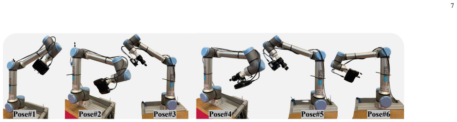
Nicole Robinson, Brendan Tidd, Dylan Campbell, Dana Kuli ´c, and Peter Corke. Robotic vision for human-robot interaction and collaboration: A survey and systematic review. ACM Transactions on Human-Robot Interaction, 12(1):1–66, 2023. 7 Pose#1Pose#2Pose#3Pose#4Pose#5Pose#6 Fig. 10. Different poses used in our proposed hand-eye calibration method. /uni0000...
work page 2023
-
[5]
Review of vision-based safety systems for human-robot collaboration
Roni-Jussi Halme, Minna Lanz, Joni K ¨am¨ar¨ainen, Roel Pieters, Jyrki Latokartano, and Antti Hietanen. Review of vision-based safety systems for human-robot collaboration. Procedia Cirp, 72:111–116, 2018
work page 2018
-
[6]
Deep learning on 3d object detection for automatic plug-in charging using a mobile manipulator
Zhengxue Zhou, Leihui Li, Riwei Wang, and Xuping Zhang. Deep learning on 3d object detection for automatic plug-in charging using a mobile manipulator. In 2021 IEEE International Conference on Robotics and Automation (ICRA) , pages 4148–4154. IEEE, 2021
work page 2021
-
[7]
Grasp pose detection in point clouds
Andreas Ten Pas, Marcus Gualtieri, Kate Saenko, and Robert Platt. Grasp pose detection in point clouds. The International Journal of Robotics Research, 36(13-14):1455–1473, 2017
work page 2017
-
[8]
Path planning with automatic seam extraction over point cloud models for robotic arc welding
Peng Zhou, Rui Peng, Maggie Xu, Victor Wu, and David Navarro- Alarcon. Path planning with automatic seam extraction over point cloud models for robotic arc welding. IEEE robotics and automation letters , 6(3):5002–5009, 2021
work page 2021
Show all 35 references
-
[9]
Hand-eye calibration
Radu Horaud and Fadi Dornaika. Hand-eye calibration. The interna- tional journal of robotics research , 14(3):195–210, 1995
1995
-
[10]
An overview of hand-eye calibration
Jianfeng Jiang, Xiao Luo, Qingsheng Luo, Lijun Qiao, and Minghao Li. An overview of hand-eye calibration. The International Journal of Advanced Manufacturing Technology, 119(1):77–97, 2022
2022
-
[11]
A comparative review of hand-eye calibration techniques for vision guided robots
Ikenna Enebuse, Mathias Foo, Babul Salam Ksm Kader Ibrahim, Hafiz Ahmed, Fhon Supmak, and Odongo Steven Eyobu. A comparative review of hand-eye calibration techniques for vision guided robots. IEEE Access, 9:113143–113155, 2021
2021
-
[12]
Accuracy evaluation of hand-eye calibration techniques for vision-guided robots
Ikenna Enebuse, Babul KSM Kader Ibrahim, Mathias Foo, Ranveer S Matharu, and Hafiz Ahmed. Accuracy evaluation of hand-eye calibration techniques for vision-guided robots. Plos one, 17(10):e0273261, 2022
2022
-
[13]
Eye-to-hand coordination for vision-guided robot control applications
SW Wijesoma, DFH Wolfe, and RJ Richards. Eye-to-hand coordination for vision-guided robot control applications. The International Journal of Robotics Research , 12(1):65–78, 1993
1993
-
[14]
A new technique for fully autonomous and efficient 3 d robotics hand/eye calibration
Roger Y Tsai, Reimar K Lenz, et al. A new technique for fully autonomous and efficient 3 d robotics hand/eye calibration. IEEE Transactions on robotics and automation , 5(3):345–358, 1989
1989
-
[15]
Optimal hand-eye calibration
Klaus H Strobl and Gerd Hirzinger. Optimal hand-eye calibration. In 2006 IEEE/RSJ international conference on intelligent robots and systems, pages 4647–4653. IEEE, 2006
2006
-
[16]
Which pattern? biasing aspects of planar calibration patterns and detection methods
John Mallon and Paul F Whelan. Which pattern? biasing aspects of planar calibration patterns and detection methods. Pattern recognition letters, 28(8):921–930, 2007
2007
-
[17]
One-step solving the hand–eye calibra- tion by dual kronecker product
Xiao Wang and Hanwen Song. One-step solving the hand–eye calibra- tion by dual kronecker product. Journal of Mechanisms and Robotics , 16(10), 2024
2024
-
[18]
Globally optimal symbolic hand-eye calibration
Jin Wu, Ming Liu, Yilong Zhu, Zuhao Zou, Ming-Zhe Dai, Chengxi Zhang, Yi Jiang, and Chong Li. Globally optimal symbolic hand-eye calibration. IEEE/ASME Transactions on Mechatronics , 26(3):1369– 1379, 2020
2020
-
[19]
Simultaneously calibration of multi hand–eye robot system based on graph
Zishun Zhou, Liping Ma, Xilong Liu, Zhiqiang Cao, and Junzhi Yu. Simultaneously calibration of multi hand–eye robot system based on graph. IEEE Transactions on Industrial Electronics , 71(5):5010–5020, 2023
2023
-
[20]
Multi-camera hand-eye calibration for human-robot collaboration in industrial robotic workcells
Davide Allegro, Matteo Terreran, and Stefano Ghidoni. Multi-camera hand-eye calibration for human-robot collaboration in industrial robotic workcells. arXiv preprint arXiv:2406.11392 , 2024
2024 arXiv
-
[21]
Modeling and calibration of high-order joint-dependent kinematic errors for industrial robots
Le Ma, Patrick Bazzoli, Patrick M Sammons, Robert G Landers, and Douglas A Bristow. Modeling and calibration of high-order joint-dependent kinematic errors for industrial robots. Robotics and Computer-Integrated Manufacturing, 50:153–167, 2018
2018
-
[22]
Automatic robot hand-eye calibration enabled by learning-based 3d vision
Leihui Li, Xingyu Yang, Riwei Wang, and Xuping Zhang. Automatic robot hand-eye calibration enabled by learning-based 3d vision. Journal of Intelligent & Robotic Systems , 110(3):130, 2024
2024
-
[23]
Generative adversarial networks for solving hand-eye calibration without data correspondence
Ilkwon Hong and Junhyoung Ha. Generative adversarial networks for solving hand-eye calibration without data correspondence. IEEE Robotics and Automation Letters , 2025
2025
-
[24]
Point cloud registration- enabled globally optimal hand–eye calibration
Dahu Zhu, Hao Wu, Tao Ding, and Lin Hua. Point cloud registration- enabled globally optimal hand–eye calibration. IEEE/ASME Transac- tions on Mechatronics , 2024
2024
-
[25]
Calibration of wrist-mounted robotic sensors by solving homogeneous transform equations of the form ax= xb
Yiu Cheung Shiu and Shaheen Ahmad. Calibration of wrist-mounted robotic sensors by solving homogeneous transform equations of the form ax= xb. 1987
1987
-
[26]
Simultaneous robot/world and tool/flange calibration by solving homogeneous trans- formation equations of the form ax= yb
Hanqi Zhuang, Zvi S Roth, and Raghavan Sudhakar. Simultaneous robot/world and tool/flange calibration by solving homogeneous trans- formation equations of the form ax= yb. IEEE Transactions on Robotics and Automation, 10(4):549–554, 1994
1994
-
[27]
A noise-tolerant algorithm for robotic hand-eye calibration with or without sensor orientation measure- ment
Hanqi Zuang and Yiu Cheung Shiu. A noise-tolerant algorithm for robotic hand-eye calibration with or without sensor orientation measure- ment. IEEE transactions on systems, man, and cybernetics , 23(4):1168– 1175, 1993
1993
-
[28]
New probabilistic approaches to the ax= xb hand-eye calibration without correspondence
Qianli Ma, Haiyuan Li, and Gregory S Chirikjian. New probabilistic approaches to the ax= xb hand-eye calibration without correspondence. In 2016 IEEE international conference on robotics and automation (ICRA), pages 4365–4371. IEEE, 2016
2016
-
[29]
Solving the robot-world hand- eye (s) calibration problem with iterative methods
Amy Tabb and Khalil M Ahmad Yousef. Solving the robot-world hand- eye (s) calibration problem with iterative methods. Machine Vision and Applications, 28(5):569–590, 2017
2017
-
[30]
Probabilistic framework for hand–eye and robot–world calibration ax = yb
Junhyoung Ha. Probabilistic framework for hand–eye and robot–world calibration ax = yb. IEEE Transactions on Robotics, 39(2):1196–1211, 2022
2022
-
[31]
General hand–eye calibration based on reprojection error minimization
Kenji Koide and Emanuele Menegatti. General hand–eye calibration based on reprojection error minimization. IEEE Robotics and Automa- tion Letters, 4(2):1021–1028, 2019
2019
-
[32]
Hand–eye calibration algorithm based on an optimized neural network
Jiang Hua and Liangcai Zeng. Hand–eye calibration algorithm based on an optimized neural network. In Actuators, volume 10, page 85. MDPI, 2021
2021
-
[33]
Learning to calibrate-estimating the hand-eye transformation without calibration objects
Krittin Pachtrachai, Francisco Vasconcelos, Philip Edwards, and Danail Stoyanov. Learning to calibrate-estimating the hand-eye transformation without calibration objects. IEEE Robotics and Automation Letters , 6(4):7309–7316, 2021
2021
-
[34]
Con- tinual learning approaches to hand–eye calibration in robots
Ozan Bahadir, Jan Paul Siebert, and Gerardo Aragon-Camarasa. Con- tinual learning approaches to hand–eye calibration in robots. Machine Vision and Applications , 35(4):97, 2024
2024
-
[35]
Predator: Registration of 3d point clouds with low overlap
Shengyu Huang, Zan Gojcic, Mikhail Usvyatsov, Andreas Wieser, and Konrad Schindler. Predator: Registration of 3d point clouds with low overlap. In Proceedings of the IEEE/CVF Conference on computer vision and pattern recognition , pages 4267–4276, 2021
2021
Reviewed August 16, 2026 · model on record in the stance chip above.
Discussion (0). Continue with ORCID to comment.