REVIEW 3 major objections 6 minor 12 references
Next Generation LLRF Control and Monitoring System for S-Band Linear Accelerators
T0 review · 3 major / 6 minor · reviewed 2026-08-07 · deepseek-v4-flash
Pith's one-line read An RFSoC-based direct RF sampling LLRF platform can meet S-band linac pulse-to-pulse stability requirements, achieving 0.0196° phase fluctuation with a two-ADC subtraction scheme, below the LCLS 0.07° specification.
desk verdict Useful S-band RFSoC loopback data and high-power waveforms, but the 0.0196° stability claim is a differential ADC measurement and shouldn't be compared to the LCLS absolute spec. read the letter →
The pith
A machine-rendered reading of the paper's core claim, the machinery that carries it, and where it could break.
The reading
What carries the argument
The central object is the RF system-on-chip (RFSoC), which integrates RF data converters, FPGA, and processor on one chip, enabling direct RF sampling: the DAC synthesizes an S-band pulse at 2856 MHz via digital up-conversion with a numerically controlled oscillator (NCO), and the ADC samples it directly at up to 4.9512 GSPS, with digital down-conversion and decimation in firmware. The comparison between two devices, ZU49DR (2.5 GSPS ADC) and ZU48DR (5 GSPS ADC), isolates the effect of ADC sample rate. The common-mode subtraction technique divides the DAC output into two ADC channels and subtracts their digitized samples to cancel noise shared by the two paths, specifically phase noise introduced by the NCO and digital mixing. This mechanism carries the paper's stability results and the claim that the platform can meet S-band specs.
What would settle it
Attach an external stable reference oscillator to the RFSoC clock and run a closed-loop test on a real S-band accelerating structure driven by a klystron; if the pulse-to-pulse phase fluctuation of the cavity field against the external reference exceeds the LCLS 0.07° specification (or the 0.0196° subtraction number is not reproduced when klystron phase noise is present), the central claim would fail.
Extended reading notes
Core claim
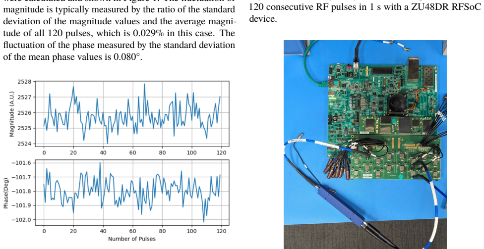
The central claim is that the RFSoC-based NG-LLRF, originally developed for C-band structures, can meet the more stringent short-term stability requirements of S-band LLRF applications when paired with a higher-rate ADC and a common-mode subtraction step. Direct loop-back tests with the ZU48DR device yield 0.023% magnitude and 0.050° phase fluctuation in 1 s at 2856 MHz and 120 Hz pulse rate; splitting the DAC output into two ADC channels and subtracting their samples reduces the phase fluctuation to 0.0196°, which is considerably lower than the LCLS specification. The paper also reports preliminary high-power measurements at NLCTA showing that the NG-LLRF can record cavity forward, reflection, and probe RF pulses with the expected filling and dissipation dynamics, verifying that the direct sampling channel can serve as a precision RF monitor for an S-band structure.
Load-bearing premise
The stability numbers come from loopback tests in which the same chip's DAC drives its own ADCs, and the best result is a difference between two ADC channels, so it measures differential, common-mode-rejected noise rather than the absolute phase stability of a real RF plant referenced to an external signal.
Editorial extensions
If this is right
- Existing S-band facilities like LCLS could upgrade LLRF from heterodyne hardware to a single-chip direct sampling platform, removing extensive analog mixer chains.
- Because down-conversion is fully digital with a tunable NCO frequency, the same board can be software-retuned to different S-band frequencies without hardware changes.
- The higher-rate ADC on ZU48DR yields approximately 20% and 40% improvements in magnitude and phase stability over ZU49DR, informing device selection for future LLRF systems.
- The two-ADC subtraction technique provides a route to sub-0.02° pulse-to-pulse phase jitter for applications with the most stringent phase specifications.
- The high-power NLCTA results indicate the NG-LLRF can simultaneously record forward, reflected, and probe signals from an S-band structure, supporting future field monitoring and closed-loop control.
- None
Reading between the lines
- The 0.0196° result is a differential measurement between two ADCs fed from the same DAC; an external phase reference not common to both channels, such as a master oscillator driving a klystron, would inject noise that subtraction cannot remove, so the absolute closed-loop stability may be poorer.
- Because instability in direct-sampling LLRF shifts from analog mixers to the ADC clock and NCO, the key performance driver is the chip's sampling clock quality; measurements on commercial evaluation boards may not carry over to custom boards with different clock distribution.
- A testable extension is to feed the same S-band RF pulse to two separate RFSoC boards locked to the same external reference and measure their relative phase; the residual would separate chip-level jitter from plant-level noise.
- The improvement attributed to ADC sample rate is inferred from comparing two different device families, so it is not a pure sample-rate effect; a same-device test at two sample rates would isolate that factor.
- None
Editorial analysis
A structured set of objections, weighed in public.
Referee Report
Summary. The paper reports an RFSoC-based direct-sampling LLRF platform extended from C-band to S-band. Loop-back measurements on ZU49DR and ZU48DR evaluation boards give pulse-to-pulse magnitude/phase fluctuations of 0.029%/0.080° and 0.023%/0.050°, respectively; a two-ADC common-mode subtraction variant on ZU48DR gives 0.0196° (19.06 fs). An open-loop high-power measurement at NLCTA captures cavity forward, reflection, and probe pulses. The paper claims these results meet or exceed LCLS short-term stability specifications and constitute an upgrade path for S-band accelerators.
Significance. The direct RF sampling architecture is a promising simplification for LLRF systems, and the paper demonstrates that the RFSoC data converters can capture S-band pulses with reasonable fidelity, including expected cavity filling and decay behavior. The phase-to-jitter conversions are arithmetically correct, and the high-power waveforms show the expected physics. However, the headline stability numbers are measured in self-loopback configurations, and the best value is a two-channel differential measurement, so the central quantitative claim of meeting LCLS absolute stability requirements is not established by the presented data.
major comments (3)
- [Pulse-to-pulse Stability with a ZU48DR Device (Figure 4)] The 0.0196° phase fluctuation is obtained by subtracting the samples of two ADCs that digitize the same DAC-generated RF signal. This removes common-mode noise from the RF source, the shared clock, the NCO, and the digital mixers, leaving only differential noise between the two ADC/down-conversion paths. The LCLS specification of 0.07° from reference [12] is an absolute cavity-field stability requirement relative to the machine reference; comparing a differential channel-mismatch number to that specification is not valid. A single-channel measurement against an external stable reference, or a closed-loop demonstration on the S-band stand, is needed to support the stated claim.
- [Pulse-to-pulse Stability with a ZU49DR Device / ZU48DR Device] The single-channel loop-back values (0.080° on ZU49DR, 0.050° on ZU48DR) are also self-referential: the RFSoC's own DAC drives its own ADC on the same board, so common reference and clock noise is correlated and real-plant effects (modulator, klystron, cavity filling, beam loading, external reference) are absent. These results should be presented as component-level data-converter characterizations rather than as demonstrations that the system meets LCLS system-level stability specifications.
- [HIGH-POWER RF MEASUREMENT AT NLCTA WITH NG-LLRF] The high-power test is an open-loop measurement only. The text states that the goal was 'to verify that the NG-LLRF can measure the RF pulse with reasonable precision' and that the test stand was driven by the original RF drive system. The final sentence, 'More results will be published with the full S-band NG-LLRF developed,' confirms that closed-loop control and absolute stability against a reference have not yet been demonstrated. The paper should distinguish the verified measurement capability from the unverified stability claim.
minor comments (6)
- [Figure 2 caption] The caption says 'with a ZC48DR device' but should read 'with a ZU48DR device'.
- [Figure 1 and Figure 2 captions; ZU48DR section] The captions contain 'and and', and the ZU48DR section says '5 GPSP' instead of '5 GSPS'.
- [Pulse-to-pulse Stability with a ZU48DR Device] The stated phase-fluctuation improvement of 40.0% when comparing 0.080° (ZU49DR) with 0.050° (ZU48DR) is actually 37.5%; please correct the percentage.
- [Pulse-to-pulse Stability with a ZU48DR Device] The sentence 'The magnitude and phase fluctuation levels are lower than the lowest short-term stability specifications 0.08% and 0.07° of all the LCLS sectors [12]' should specify which sectors and whether [12] indeed gives these as absolute requirements.
- [HIGH-POWER RF MEASUREMENT AT NLCTA WITH NG-LLRF] For the high-power measurement, please report the ADC sampling rate, decimation, and NCO settings used at 2853.8 MHz to allow reproducibility.
- [RF PERFORMANCE EVALUATION] Consider adding measurement uncertainty or error bars to the quoted stabilities and specifying the number of pulses and the averaging window beyond the 120 pulses mentioned.
Circularity Check
No significant circularity: the stability results are measured statistics compared against an external LCLS specification, with no fitted inputs or self-citation-derived claims.
full rationale
The paper contains no fitted model, no parameter trained on a subset and then renamed as a prediction, and no derivation chain that reduces to its own inputs. The central results are directly measured pulse-to-pulse magnitude and phase fluctuations obtained by digitizing loopback or coupler signals. The 0.0196 degree figure is produced by subtracting two ADC channels that sample the same DAC-generated RF signal; this is a measurement technique analogous to common-mode rejection, not a quantity equal to the LCLS comparison by construction. The comparison to the 0.07 degree LCLS specification is an external benchmark rather than an input to the measurement. Self-citations to prior RFSoC and NG-LLRF work are contextual and document prior platform development; no load-bearing argument reduces to a self-cited uniqueness theorem, ansatz, or unverified premise. Even if the differential loopback measurement is not directly comparable to an absolute single-channel stability specification, that is a measurement-validity concern, not circularity. The paper is self-contained against external benchmarks and its claims are experimentally sourced, so no circular step is identified.
Assumptions & free parameters
assumptions (4)
- domain assumption The same-chip DAC-to-ADC loopback measurement represents the pulse-to-pulse stability the system would provide in an accelerator LLRF application.
- standard math Phase fluctuation in degrees converts linearly to time jitter at the fixed RF frequency of 2856 MHz.
- domain assumption The high-power cavity signals recorded at NLCTA (forward, reflection, probe) are faithful representations of the cavity fields after attenuation and direct sampling.
- domain assumption The LCLS short-term stability specification is the appropriate external benchmark for S-band LLRF.
Cite this review
Pith. "Pith review of Next Generation LLRF Control and Monitoring System for S-Band Linear Accelerators." pith.science (2026). https://pith.science/paper/IUKM3XCG
@misc{pith2026250522876,
  author       = {Pith},
  title        = {Pith review of: Next Generation LLRF Control and Monitoring System for S-Band Linear Accelerators},
  year         = {2026},
  howpublished = {\url{https://pith.science/paper/IUKM3XCG}},
  note         = {Machine review of arXiv:2505.22876}
}
read the original abstract
The low-level RF (LLRF) systems for S-band linear accelerating structures are typically implemented with heterodyne base architectures. We have developed and characterized the next generation LLRF (NG-LLRF) based on the RF system-on-chip (RFSoC) for C-band accelerating structures, and the platform delivered the pulse-to-pulse fluctuation levels considerably better than the requirement of the targeted applications. The NG-LLRF system uses the direct RF sampling technique of the RFSoC, which significantly simplified the architecture compared to the conventional LLRF. We have extended the frequency range of the NG-LLRF to S-band and experimented with different RFSoC devices and system designs to meet the more stringent requirements for S-band LLRF applications. In this paper, the characterization results of the platform with different system architectures will be summarized and the high-power test results of the NG-LLRF with the S-band accelerating structure in the Next Linear Collider Test Accelerator (NLCTA) test facility at the SLAC National Accelerator Laboratory will be presented and analyzed.
Figures


Figures from the paper (1 more)

Reference graph
Works this paper leans on
-
[12]
LCLS LLRF upgrades to the SLAC linac
R. Akreet al., “LCLS LLRF upgrades to the SLAC linac ”, 2007 IEEE Particle Accelerator Conference (PAC), p. 2421- 2423, 2007
work page 2007
-
[1]
Next Generation LLRF Control Platform for CompactC-bandLinearAccelerator
C. Liuet al., “Next Generation LLRF Control Platform for CompactC-bandLinearAccelerator”,LCWS2024,EPJWebof Conferences, vol. 315, no. 4, p. 02008, 2024.doi:10.1051/ epjconf/202431502008
arXiv 2024
-
[2]
E.Nannietal.,“ESPPUINPUT:C3withinthe"LinearCollider Vision" ”,arXiv preprint arXiv:2503.20829, 2025.https: //arxiv.org/abs/2503.20829
arXiv 2025
-
[3]
C. Liuet al., “Characterizing the performance of high-speed data converters for RFSoC-based radio astronomy receivers”, Monthly Notices of the Royal Astronomical Society, vol. 501, no.4, p.5096–5104, 2021. doi:10.1093/mnras/staa3895
-
[4]
C. Liuet al., “Development of General-purpose Digi- tal Backend for Single-dish Centimetre and Millimetre- wave Telescopes”,2022 3rd URSI Atlantic and Asia Pa- cific Radio Science Meeting (AT-AP-RASC),doi:10.23919/ AT-AP-RASC54737.2022.9814190
arXiv 2022
-
[5]
Advanced RFSoC readout for space-based superconducting sensor arrays
S. Henderson, C. Liuet al., “Advanced RFSoC readout for space-based superconducting sensor arrays”,Millimeter, Sub- millimeter,andFar-InfraredDetectorsandInstrumentationfor Astronomy XI, vol. 12190, p. 339-355, 2022.doi:10.1117/ 12.2630412
2022
-
[6]
Evaluating Direct RF Sampling Performance for RFSoC-based Radio-frequency Astronomy Receivers
C. Liuet al., “Evaluating Direct RF Sampling Performance for RFSoC-based Radio-frequency Astronomy Receivers”, 2023 XXXVth General Assembly and Scientific Symposium of the International Union of Radio Science (URSI GASS), arXivpreprintarXiv:2309.08067
arXiv 2023
-
[7]
C. Liuet al., “Higher order nyquist zone sampling with rf- soc data converters for astronomical and high energy physics readout systems”,2023 IEEE Nuclear Science Symposium and Medical Imaging Conference,arXivpreprintarXiv: 2309.08640
arXiv 2023
Show all 12 references
-
[8]
Development of RFSoC-based direct sampling highlymultiplexedmicrowaveSQUIDreadoutforfutureCMB and submillimeter surveys
C. Liuet al., “Development of RFSoC-based direct sampling highlymultiplexedmicrowaveSQUIDreadoutforfutureCMB and submillimeter surveys”,2024 SPIE Astronomical Tele- scopes + Instrumentation,doi:10.1117/12.3019317
2024 doi
-
[9]
Direct rf sampling based LLRF control sys- tem for C-band linear accelerator
C. Liuet al., “Direct rf sampling based LLRF control sys- tem for C-band linear accelerator”,IPAC’24 - 15th Inter- national Particle Accelerator Conference, p. 25-28, 2024. doi:10.18429/JACoW-IPAC2024-MOCN2
2024 doi
-
[10]
High-powertestofaC-bandlinearaccelerating structure with an RFSoC-based LLRF system
C.Liuetal.,“High-powertestofaC-bandlinearaccelerating structure with an RFSoC-based LLRF system”,Review of Scientific Instruments,vol. 96, no. 4, 2025.doi:10.1063/5. 0258520
2025 doi
-
[11]
A Compact Low-level RF Control System for Advanced Concept Compact Electron Linear Accelerator
C. Liuet al., “A Compact Low-level RF Control System for Advanced Concept Compact Electron Linear Accelerator”, Submitted to Review of Scientific Instruments, 2025https: //arxiv.org/abs/2502.10623
Reviewed August 7, 2026 · model on record in the stance chip above.
Discussion (0). Sign in to comment.