REVIEW 2 major objections 5 minor 43 references
High-precision polarization measurements with Lumped Element Kinetic Inductance Detectors
T0 review · 2 major / 5 minor · reviewed 2026-08-06 · deepseek-v4-flash
Pith's one-line read Two LEKID arrays measure polarization angle to 6.5 arcmin
desk verdict A real precision measurement in the lab, but the CMB-ready claim only works if you treat statistical scatter as absolute calibration, which it is not. read the letter →
The pith
A machine-rendered reading of the paper's core claim, the machinery that carries it, and where it could break.
The reading
What carries the argument
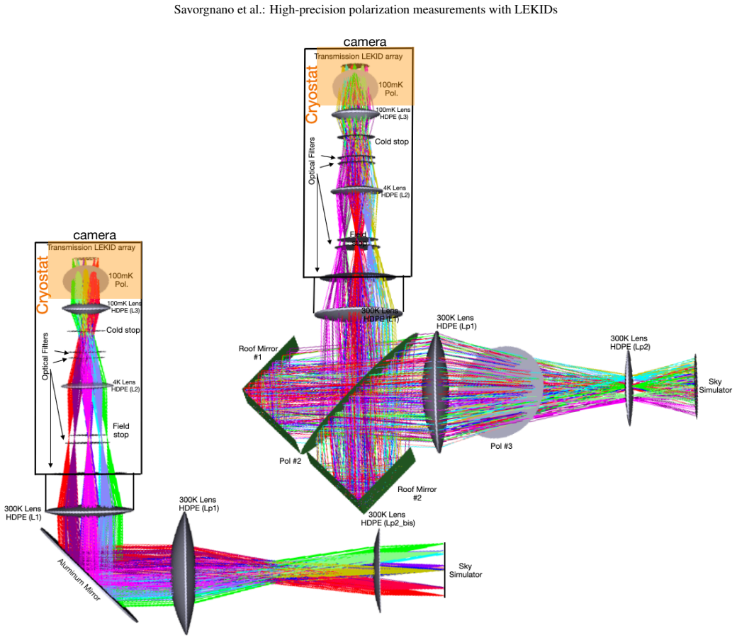
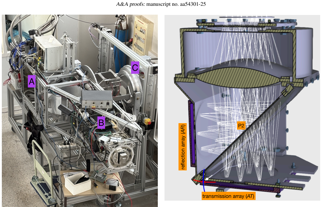
The load-bearing mechanism is the two-arm polarization splitter formed by the two mutually perpendicular LEKID arrays and the 45-degree wire-grid polarizer P2 between them: the transmission array records one linear polarization while the reflection array records the orthogonal one, giving a 90-degree phase separation. The quantitative core is the Mueller-matrix model $V = 1 + \sin 2\alpha \cos 2\beta + \cos 2\alpha \sin 2\beta$, where $\alpha$ is the rotated source polarizer's angle and $\beta$ is the cold polarizer's orientation; fitting this model to the measured intensity-versus-angle curves with a Monte Carlo Markov Chain returns $\beta$ and its uncertainty. This model is what converts raw detector maps into a polarization angle, and the width of its fitted parameter distribution is the claimed 0.1-degree precision.
What would settle it
Measure the absolute orientation of the cold polarizer P2 independently to better than 0.05 degrees, for instance with a theodolite sighting through the optical path, and repeat the polarization-curve fit; if the independently measured angle differs from the fitted $\beta = 0.8^\circ$ by more than the claimed uncertainty, then 6.5 arcmin is a relative precision rather than an absolute angle accuracy.
Extended reading notes
Core claim
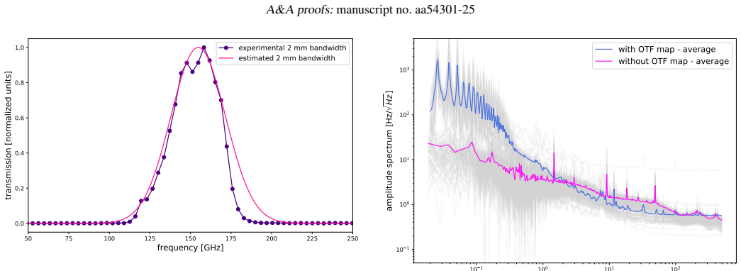
The paper's central claim is that a focal plane built from two perpendicular LEKID arrays, with a wire-grid polarizer at 45 degrees splitting the incoming beam, measures the linear polarization angle of a 150 GHz source with an uncertainty of 6.5 arcmin (about 0.1 degrees), meeting the target that next-generation CMB experiments set for absolute polarization calibration. The claim is supported by a laboratory polarization curve: the source polarizer was rotated in 15-degree steps, the detected flux was integrated by aperture photometry on the two arrays, and a Mueller-matrix model fitted to those curves returned the cold polarizer angle $\beta = 0.8^\circ \pm 0.1^\circ$. The same measurements give a cross-polarization of about 1% and a pixel noise equivalent power of about $1.5 \times 10^{-16}$ W per root hertz, within roughly a factor 1.1 of the photon-noise limit. The paper concludes that LEKID filled arrays can meet the angle-precision requirement for CMB B-mode searches.
Load-bearing premise
The result treats the fitted 0.1-degree scatter as the total polarization-angle uncertainty, even though the paper states that the cold polarizer's orientation was only set to within one degree, so if that alignment uncertainty dominates, the absolute angle accuracy is about one degree rather than 0.1 degrees.
Editorial extensions
If this is right
- If the central claim holds, LEKID filled arrays become viable focal planes for CMB experiments targeting tensor-to-scalar ratios around $r \sim 10^{-3}$, where a polarization-angle error of 0.1 degrees keeps E-to-B leakage at the multipoles that matter.
- The demonstrated test bench can serve as a qualification facility for other millimeter-wave cameras, since it produces diffraction-limited intensity and polarization maps under realistic ground-based optical loading.
- The measured noise equivalent power, close to the photon-noise limit, implies that a ground-based 150 GHz instrument using these arrays would not be limited by detector noise in the 1-10 Hz band used for polarization modulation.
- The path to wider deployment is the paper's stated plan: extend the analysis from the best 30% of pixels to full arrays, scale toward roughly 30,000 detectors, and validate the result at 250 GHz.
Reading between the lines
- Beyond the paper: the 0.1-degree figure is the statistical width of the fitted cold-polarizer angle, and the absolute accuracy inherits the roughly one-degree leveling uncertainty of that polarizer, so the headline precision is best read as relative reproducibility until an externally calibrated absolute reference is used.
- Beyond the paper: the same Mueller-matrix procedure should transfer to on-sky operation with a rotating half-wave plate, where the sky itself acts as the rotating source, providing a direct end-to-end test of the angle calibration.
- Beyond the paper: because the paper identifies setup alignment as the dominant uncertainty, replacing the microscope-leveled source polarizer with an absolutely calibrated polarizing source is a straightforward improvement path that could push the stated uncertainty below 0.1 degrees and is testable with the existing apparatus.
Signed reviews
Editorial analysis
A structured set of objections, weighed in public.
Referee Report
Summary. The manuscript presents a laboratory characterization of two filled-array LEKID cameras operating at 150 GHz, configured with a 45° linear polarizer between them. Using a sky simulator with a rotating wire-grid polarizer (P1) as an external reference, the authors fit a Mueller-matrix model to aperture-photometry measurements to determine the orientation of the cold polarizer (P2). They report a reconstructed polarization-angle uncertainty of 6.5 arcmin (0.1°), a near-photon-noise NEP, and a forecast that this precision would bias the tensor-to-scalar ratio at r ~ 0.001. The conclusions state that the setup meets the polarization-angle requirements of next-generation CMB experiments.
Significance. If the 0.1° value is a true total absolute uncertainty, this would be a meaningful step for LEKID-based CMB polarimetry, especially compared with the ~1° statistical angle precision reported for NIKA2. The paper is also valuable for its detailed description of the test bench, including the sky simulator, Martin-Puplett interferometer, aperture photometry, MCMC fitting, and explicit discussion of cross-polarization and calibration limitations. However, the headline precision is not placed in a complete uncertainty budget, so the central CMB-readiness claim is not yet fully established.
major comments (2)
- [Abstract, §4.3, §5.1, Conclusions] The manuscript reports that the polarization angle was reconstructed with an uncertainty of 6.5 arcmin and states in the Conclusions that a precision of 0.1° meets next-generation CMB requirements. However, §5.1 explicitly defines the ±0.1° as the statistical uncertainty accounting for reproducibility and intrinsic dispersion among the KIDs, while §4.3 gives only the pre-calibration accuracy: P1 is aligned by microscope to 0.1°, and P2 is empirically leveled to 0°±1°. Although the fit may be used to calibrate P2 relative to P1, the paper never propagates the P1 reference uncertainty and the P2 placement prior into a total absolute uncertainty for the reconstructed angle. As written, the abstract and Conclusions conflate fit precision with absolute calibration accuracy; the Conclusions' own statement that the current uncertainty is dominated by the alignment and calibration of the setup undercuts the headline claim. Please provide an explicit error budget separating statistical, P1-reference, P2-alignment, and cross-polarization contributions, and adjust the abstract and conclusions accordingly.
- [§5.3, Eqs. (13)-(16), Fig. 12] The forecast for the tensor-to-scalar ratio bias uses Δψ = 0.1° as the absolute polarization-angle error. Since the paper does not establish that 0.1° is the total absolute uncertainty, the 'this work' point in Fig. 12 is not conservative. For example, adding the 0.1° P1 reference uncertainty in quadrature with the 0.1° statistical term gives Δψ ≈ 0.14°, which via Eq. (16) approximately doubles the E-to-B leakage relative to Δψ = 0.1°, and a 1° systematic floor would bring the bias to roughly the Planck level (r ~ 0.01). The forecast should be recomputed using a properly propagated total uncertainty and should include a sensitivity curve r(Δψ) over the range allowed by the setup.
minor comments (5)
- [§3.1] The reference temperatures provided by thermometers are treated as exact values without associated uncertainties; please state the estimated thermometer uncertainty and its effect on the derived effective sky-simulator temperature.
- [Eq. (4)] The text 'can also be expresses as' should read 'can also be expressed as'.
- [Fig. 12] The x-axis label appears to be missing the variable Δψ; please add it and specify the units explicitly.
- [§2.2.1 and Conclusions] Section 2.2.1 states a temperature stability of 0.1 mK at the 100 mK stage, while the Conclusions mention fluctuations within 1 mK during a typical measurement session; please reconcile these values or specify the different timescales.
- [§5.2] The parasitic cross-polarization component k(T) is estimated as approximately 1% without an associated uncertainty; please provide an uncertainty or state explicitly that this is an order-of-magnitude estimate.
Circularity Check
No circularity found: the 0.1° polarization-angle precision is a fitted calibration parameter anchored to an external rotating polarizer and forecast against published CMB spectra.
full rationale
The paper's central derivation is the fit of Eq. 11 to the measured response of two LEKID arrays as a function of the known rotation of source polarizer P1; the fitted parameter β is a calibration parameter of the cold polarizer P2, and its ±0.1° uncertainty is propagated into the CMB r-forecast using published C_EE and C_BB spectra (Planck/SO). No load-bearing step defines the target result in terms of its own inputs: the Mueller-matrix model is independent of the measurement, the fit uses encoder-provided angles as external references, and the r forecast uses externally published power spectra rather than fitted values. The paper's self-citations (NIKA/Perotto et al.) are methodological or baseline context, not the justification of the headline precision. The possible concern that 6.5 arcmin is only the statistical fit uncertainty while the absolute calibration floor from P2 is 1° is a correctness/calibration limitation acknowledged in the conclusions, not a circular reduction.
Assumptions & free parameters
free parameters (2)
- Polarizer angle β =
0.8° ± 0.1°
- Cross-polarization parasitic factor k(T) =
~1% of signal (parasitic temperature ~17 K)
assumptions (2)
- domain assumption The detector response follows the Mueller-matrix model V = 1 + sin(2α)cos(2β) + cos(2α)sin(2β) for two crossed linear polarizers.
- domain assumption The source polarizer P1 is a perfect linear polarizer with known orientation (accuracy 0.1°) and the cold polarizer P2 is linear with orientation 0°±1°.
Cite this review
Pith. "Pith review of High-precision polarization measurements with Lumped Element Kinetic Inductance Detectors." pith.science (2026). https://pith.science/paper/E45ZLYQF
@misc{pith2026250623983,
  author       = {Pith},
  title        = {Pith review of: High-precision polarization measurements with Lumped Element Kinetic Inductance Detectors},
  year         = {2026},
  howpublished = {\url{https://pith.science/paper/E45ZLYQF}},
  note         = {Machine review of arXiv:2506.23983}
}
read the original abstract
This work aims to demonstrate that two arrays of Lumped Element Kinetic Inductance Detectors (LEKIDs), when employed in filled array configuration and separated by an external linear polarizer oriented at 45 degrees, can achieve the precision required by next-generation cosmological experiments. The focus here is on validating their ability to meet stringent uncertainty requirements, in particular for polarization angle reconstruction. To achieve this, the uncertainties in the reconstruction of the polarization angle have been characterized in the laboratory using a dedicated closed-circuit 100 mK dilution cryostat. This is optically coupled to a Martin-Puplett interferometer and a custom-designed sky simulator equipped with both photometric and polarized sources, allowing one to reproduce realistic ground-based observation conditions. This experimental setup allows us to generate intensity and polarization maps with diffraction-limited resolution, allowing us to determine the polarization angles and their associated uncertainties. The results show performance in line with expectations for the next generation CMB experiments. The polarization angle was reconstructed with an uncertainty of 6.5 arcmin.
Figures

Figures from the paper (6 more)



Reference graph
Works this paper leans on
-
[1]
N., Adshead, P., Ahmed, Z., et al
Abazajian, K. N., Adshead, P., Ahmed, Z., et al. 2016, arXiv e-prints, arXiv:1610.02743
arXiv 2016
-
[2]
Adam, R., Adane, A., Ade, P. A. R., et al. 2018, A&A, 609, A115
2018
-
[3]
Ade, P., Aguirre, J., Ahmed, Z., et al. 2019, J. Cosmology Astropart. Phys., 2019, 056
2019
-
[4]
Ade, P. A. R., Akiba, Y ., Anthony, A. E., et al. 2014, Phys. Rev. Lett., 113, 021301
work page 2014
-
[5]
Aiola, S., Calabrese, E., Maurin, L., et al. 2020, J. Cosmology Astropart. Phys., 2020, 047
work page 2020
-
[6]
Ajeddig, H., André, P., Desert, F.-X., et al. 2022
work page 2022
-
[7]
F., Ritacco, A., Ponthieu, N., & Mangilli, A
Aumont, J., Macías-Pérez, J. F., Ritacco, A., Ponthieu, N., & Mangilli, A. 2020, A&A, 634, A100
work page 2020
-
[8]
2022, Journal of Instrumentation, 17, P10047
Bourrion, O., Hoarau, C., Bounmy, J., et al. 2022, Journal of Instrumentation, 17, P10047
2022
Show all 43 references
-
[9]
M., Field, G
Carroll, S. M., Field, G. B., & Jackiw, R. 1990, Phys. Rev. D, 41, 1231
1990
-
[10]
2020, A&A, 641, A179
Catalano, A., Bideaud, A., Bourrion, O., et al. 2020, A&A, 641, A179
2020
-
[11]
2015, A&A, 580, A15
Catalano, A., Goupy, J., le Sueur, H., et al. 2015, A&A, 580, A15
2015
-
[12]
R., Minami, Y ., et al
Diego-Palazuelos, P., Eskilt, J. R., Minami, Y ., et al. 2022, Phys. Rev. Lett., 128, 091302
2022
-
[13]
Diego-Palazuelos, P., Martínez-González, E., Vielva, P., et al. 2023, J. Cosmol- ogy Astropart. Phys., 2023, 044
2023
-
[14]
2009, in American Institute of Physics Conference Series, V ol
Doyle, S., Mauskopf, P., Zhang, J., et al. 2009, in American Institute of Physics Conference Series, V ol. 1185, The Thirteenth International Workshop on Low Temperature Detectors - LTD13, ed. B. Young, B. Cabrera, & A. Miller (AIP), 156–159
2009
-
[15]
2020, in European Physical Journal Web of Conferences, V ol
Fasano, A., Aguiar, M., Benoit, A., et al. 2020, in European Physical Journal Web of Conferences, V ol. 228, mm Universe @ NIKA2 - Observing the mm Universe with the NIKA2 Camera, 00010
2020
-
[16]
W., Lang, D., & Goodman, J
Foreman-Mackey, D., Hogg, D. W., Lang, D., & Goodman, J. 2013, PASP, 125, 306
2013
-
[17]
Giardiello, S., Gerbino, M., Pagano, L., et al. 2024, J. Cosmology Astropart. Phys., 2024, 008
2024
-
[18]
2016, Journal of Low Temperature Physics, 184, 661
Goupy, J., Adane, A., Benoit, A., et al. 2016, Journal of Low Temperature Physics, 184, 661
2016
-
[19]
Guth, A. H. 1981, Phys. Rev. D, 23, 347
1981
-
[20]
2019, in Bulletin of the American As- tronomical Society, V ol
Hanany, S., Alvarez, M., Artis, E., et al. 2019, in Bulletin of the American As- tronomical Society, V ol. 51, 194
2019
-
[21]
& Dodelson, S
Hu, W. & Dodelson, S. 2002, ARA&A, 40, 171
2002
-
[22]
& White, M
Hu, W. & White, M. 1997, New A, 2, 323
1997
-
[23]
2023, Phys
Jost, B., Errard, J., & Stompor, R. 2023, Phys. Rev. D, 108, 082005
2023
-
[24]
& Kovetz, E
Kamionkowski, M. & Kovetz, E. D. 2016, ARA&A, 54, 227
2016
-
[25]
G., Shimon, M., & Yadav, A
Keating, B. G., Shimon, M., & Yadav, A. P. S. 2013, ApJ, 762, L23
2013
-
[26]
M., Leitch, E
Kovac, J. M., Leitch, E. M., Pryke, C., et al. 2002, Nature, 420, 772 LiteBIRD Collaboration, Allys, E., Arnold, K., et al. 2023, Progress of Theoret- ical and Experimental Physics, 2023, 042F01 Macías-Pérez, J. F., Fernández-Torreiro, M., Catalano, A., et al. 2024, PASP, 136, 114505
2002
-
[27]
& Komatsu, E
Minami, Y . & Komatsu, E. 2020, Phys. Rev. Lett., 125, 221301
2020
-
[28]
2016, in Society of Photo- Optical Instrumentation Engineers (SPIE) Conference Series, V ol
Monfardini, A., Baselmans, J., Benoit, A., et al. 2016, in Society of Photo- Optical Instrumentation Engineers (SPIE) Conference Series, V ol. 9914, Mil- limeter, Submillimeter, and Far-Infrared Detectors and Instrumentation for Astronomy VIII, ed. W. S. Holland & J. Zmuidzina...
2016
-
[29]
2011, ApJS, 194, 24
Monfardini, A., Benoit, A., Bideaud, A., et al. 2011, ApJS, 194, 24
2011
-
[30]
J., Benoit, A., et al
Monfardini, A., Swenson, L. J., Benoit, A., et al. 2009, in EAS Publications
2009
-
[31]
J., Bideaud, A., et al
Monfardini, A., Swenson, L. J., Bideaud, A., et al. 2010, A&A, 521, A29
2010
-
[32]
F., et al
Perotto, L., Ponthieu, N., Macías-Pérez, J. F., et al. 2020, A&A, 637, A71 Planck Collaboration, Aghanim, N., Akrami, Y ., et al. 2020a, A&A, 641, A6 Planck Collaboration, Aghanim, N., Ashdown, M., et al. 2016, A&A, 596, A107 Planck Collaboration, Akrami, Y ., Arroja, F., et a...
2020
-
[33]
Polnarev, A. G. 1985, Soviet Ast., 29, 607
1985
-
[34]
M., Ade, P
Posada, C. M., Ade, P. A. R., Ahmed, Z., et al. 2015, Superconductor Science Technology, 28, 094002
2015
-
[35]
2009, Phys
Pospelov, M., Ritz, A., & Skordis, C. 2009, Phys. Rev. Lett., 103, 051302
2009
-
[36]
Rees, M. J. 1978, Nature, 275, 35
1978
-
[37]
2022, in European Physical Journal Web of
Ritacco, A., Adam, R., Ade, P., et al. 2022, in European Physical Journal Web of
2022
-
[38]
2024, PASP, 136, 115001
Ritacco, A., Bizzarri, L., Savorgnano, S., et al. 2024, PASP, 136, 115001
2024
-
[39]
2023, A&A, 670, A163
Ritacco, A., Boulanger, F., Guillet, V ., et al. 2023, A&A, 670, A163
2023
-
[40]
2017, A&A, 599, A34
Ritacco, A., Ponthieu, N., Catalano, A., et al. 2017, A&A, 599, A34
2017
-
[41]
2010, A&A, 520, A13
Rosset, C., Tristram, M., Ponthieu, N., et al. 2010, A&A, 520, A13
2010
-
[42]
J., Górski, K
Tristram, M., Banday, A. J., Górski, K. M., et al. 2021, A&A, 647, A128
2021
-
[43]
2023, A&A, 672, A146 Vergès, C., Errard, J., & Stompor, R
Vacher, L., Aumont, J., Boulanger, F., et al. 2023, A&A, 672, A146 Vergès, C., Errard, J., & Stompor, R. 2021, Phys. Rev. D, 103, 063507 Article number, page 12 of 12
2023
Reviewed August 6, 2026 · model on record in the stance chip above.
Discussion (0). Continue with ORCID to comment.