REVIEW 5 major objections 4 minor 28 references
S3D: A Spatial Steerable Surgical Drilling Framework for Robotic Spinal Fixation Procedures
T0 review · 5 major / 4 minor · reviewed 2026-08-06 · deepseek-v4-flash
Pith's one-line read A robotic drilling framework with a pre-curved steering tube autonomously creates J-shaped vertebra tunnels whose measured curvature is within 1.9 percent of the planned radius, with roughly millimeter-level tip positioning.
desk verdict A solid bench-top integration with honest numbers; the main gap is that the 'cortical bone' surrogate is cancellous foam, so the 1.9% curvature match does not transfer to real bone. read the letter →
The pith
A machine-rendered reading of the paper's core claim, the machinery that carries it, and where it could break.
The reading
What carries the argument
The load-bearing object is the CT-SDR*, a concentric-tube steerable drilling robot: a motorized rigid or flexible drill that slides inside a pre-curved Nitinol guide tube, so the tube's curvature dictates the path the flexible ball burr cuts once it leaves the straight stainless-steel housing. The paper's supporting machinery is the four-phase procedure: hand-eye calibration, formulated as an $AX = ZB$ problem, pivot calibration of the digitizer tip, digitizer-aided tip calibration of the drill tip, then pose marking, autonomous pilot-hole drilling with the rigid tool, and autonomous J-shape drilling with the flexible tool. The three calibrations build the chain of coordinate transforms that lets a surgeon's digitizer-marked entry pose become a robot command; the pre-curved tube carries the drilling phase by steering the burr after the pilot hole provides straight access through the pedicle.
What would settle it
Drill the same J-shaped protocol into fresh or cadaveric corticocancellous bone while measuring force at the robot wrist and comparing the exit path to the planned curve; if the flexible tip buckles at the pedicle, skives off the pilot-hole wall, or produces a radius deviation much larger than 1.9 percent, the phantom-based claim does not transfer.
Extended reading notes
Core claim
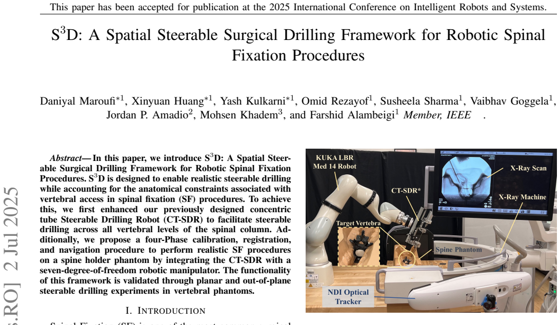
The central claim is that the S3D framework makes autonomous J-shaped steerable drilling into a realistically mounted vertebra phantom possible for the first time. A rigid 2.5 mm drill first creates a straight pilot hole through the simulated cortical pedicle; the tool is then swapped for a flexible 3.9 mm ball burr, and a pre-curved Nitinol steering tube guides the burr along a planned curve through the cancellous body. The paper reports an overall positioning error of $1.14 \pm 0.28$ mm for the rigid tip and $1.74 \pm 0.97$ mm for the flexible tip, orientation errors below 1 degree, and a drilled radius of curvature of $70.83 \pm 1.72$ mm versus the planned 69.5 mm, a 1.9 percent deviation. The authors state that to their knowledge this is the first use of such a realistic experimental setup to perform J-shaped drilling into vertebrae.
Load-bearing premise
The result rests on the assumption that a flexible burr pushed through a pre-curved metal tube into polyurethane foam behaves the same as it would in real cortical and cancellous bone, so the 1.9 percent curvature match in foam would carry over to human vertebrae.
Editorial extensions
If this is right
- The same four-phase calibration-and-navigation pipeline can be reused for other steerable drilling tools, because it depends only on generic hand-eye, pivot, and tip calibrations.
- A surgeon can specify both the entry point and the drilling angle with an optical digitizer, and the robot reproduces that pose well within the 4 mm pedicle-perforation safety threshold used clinically.
- The 1.9 percent radius-of-curvature error means a pre-bent steering tube can reliably produce the planned tunnel shape in a foam vertebra, making planned curved screw paths feasible at the benchtop level.
- Covering the cortical pedicle with a pilot hole and then reaming it with the flexible burr is demonstrated in foam, which is the step needed before moving from bone blocks to whole-vertebra experiments.
Reading between the lines
- Because force and torque during the curved pass are not reported, a natural next test is instrumenting the drill to find feed rates and tube curvatures at which the flexible burr starts to buckle or skive at the pedicle; that would extend the empirical accuracy claim into a stability envelope.
- The adjustable chucks are claimed to cover all vertebral levels, but the experiments use one tube curvature and one level; testing smaller-diameter, tighter-radius guides in a cervical-scale phantom would directly test that generalization.
- Only the planar J-shape is measured quantitatively; the out-of-plane case is shown qualitatively, so a quantitative spatial error metric for the out-of-plane trajectory would be the immediate missing validation.
- If the foam phantoms faithfully represent osteoporotic bone, the framework points toward a clinical workflow where the surgeon marks one pose and the robot drills a curved tunnel that a flexible pedicle screw can follow, but transfer to real tissue still requires the cadaver and animal studies the authors list as future work.
Editorial analysis
A structured set of objections, weighed in public.
Referee Report
Summary. The paper introduces S3D, a framework that integrates a redesigned concentric-tube steerable drilling robot (CT-SDR*) with a 7-DoF KUKA arm and an NDI optical tracker, together with a four-phase calibration/registration/navigation procedure (hand-eye, pivot, and digitizer-aided tip calibration; pose marking; pilot-hole drilling; J-shape drilling). Experiments on a 3D-printed L3 vertebra phantom embedded in a spine holder, with PCF 5 and PCF 15 Sawbone materials, yield calibration/registration errors of 1.14 mm (rigid) and 1.74 mm (flexible) with sub-degree orientation errors, and a measured radius of curvature of 70.83 +/- 1.72 mm versus a planned 69.5 mm (1.9% error) for three planar holes. One out-of-plane trajectory is demonstrated but is not quantitatively assessed. The authors claim this is the first realistic experimental setup for J-shaped drilling into vertebrae.
Significance. The framework's calibration pipeline is clearly described and the headline error metrics are independently measured (CAD-based curvature, optical-tracker-based pose errors); no fitted parameters are used to produce the reported accuracy. If the results transfer to more realistic bone models, this would be a meaningful step toward autonomous curved drilling for spinal fixation. The main value is the integration of existing steerable-drilling hardware with a complete calibration/registration/navigation loop, going beyond prior single-level or simulated-bone studies. However, the significance is currently bounded by the phantom material choice, the small number of drilling trials, and the unquantified out-of-plane case, which limit the strength of the 'realistic' and 'spatial' claims rather than the validity of the calibration mathematics.
major comments (5)
- [III-A, III-B.2, IV] The central curvature validation (70.83 +/- 1.72 mm vs 69.5 mm, 1.9% error) is performed in a phantom whose pedicle 'cortical bone' is PCF 15 Sawbone and whose body is PCF 5 Sawbone. PCF 15 is a cancellous-bone analog (ASTM F1839), with density and compressive strength roughly an order of magnitude below cortical bone. During Phase 4, the 3.9 mm flexible ball burr must ream the 2.5 mm pilot hole through this layer before curving, but the paper reports no force/torque data or test in a cortical-like shell. The 1.9% curvature match therefore does not yet support the claim that the approach works in cortical bone, and the 'realistic' setup statement should be revised accordingly.
- [IV, Fig. 6B] The out-of-plane trajectory is shown only as X-ray images in Fig. 6B, with no quantitative accuracy measure; Section IV states that quantitative analysis was done only for planar transverse-plane holes. Since the abstract and introduction emphasize 'spatial' and 'out-of-plane' drilling, this is a gap in the evidence. Please provide quantitative out-of-plane error metrics (e.g., reconstructed trajectory deviation or curvature error) or restrict the claims to planar validation.
- [II-A, V] The claim that the CT-SDR* 'facilitate[s] steerable drilling across all vertebral levels of the spinal column' is not supported by the experiments, which use only a single L3 phantom. The adjustable chucks broaden compatibility, but no cervical, thoracic, or differently sized vertebra was tested. The 'all vertebral levels' statement should either be supported by additional experiments or replaced by a statement about design capability.
- [Table I, IV] The orientation errors in Table I have large standard deviations (e.g., flexible-tip yaw 0.80 +/- 1.16 deg), so the statement 'orientation error was also less than 1 degree' is not guaranteed for all trials. The number of repeated measurements is not reported. Please report the number of trials, individual errors, and/or confidence intervals to support the sub-degree claim and the subsequent safety-margin discussion.
- [V] The claim 'to the best of our knowledge this is the first time to use such realistic experimental setup to perform J-shaped drilling into the vertebrae' is stronger than the presented evidence: the test is a 3D-printed L3 phantom with foam inserts and only one unquantified out-of-plane case. I recommend a more precise claim that describes the specific integration, for example 'first integration of a steerable drilling robot, optical tracking, and a seven-DoF arm for J-shaped drilling in a spine phantom.'
minor comments (4)
- [II-B.1, Eq. (1)] The frame notation appears inconsistent: drillTPolaris is described as the transformation of the optical tracker frame with respect to the drill frame, which would conventionally be written PolarisTdrill; please clarify the convention.
- [III-A] The phantom material is described as ABS in one place and PLA in another; please correct the inconsistency.
- [IV, Fig. 6A] The CAD-based curvature measurement lacks details on how the circle was fitted to the sliced trajectory and how the reported uncertainty (1.72 mm) was computed; please add a brief description of the fitting procedure.
- [Throughout] Please copyedit for typos: 'cancelous' should be 'cancellous', 'Mcmaster-Carr' should be 'McMaster-Carr', and 'Sas interational' should be 'SAS International'.
Circularity Check
No circularity: the framework's calibration and curvature results are independently measured against physical ground truth.
full rationale
The paper's derivation chain is experimental rather than analytic, and the central quantitative claims are measured against independent physical references. The planned J-shape radius of curvature (69.5 mm) is the manufactured specification of the pre-curved NiTi steering tube, not a value fitted from the drilling outcome; the reported 70.83 +/- 1.72 mm radius is obtained by slicing the drilled Sawbone phantom and measuring the trajectory in CAD, so the 1.9% agreement is an empirical conformance check, not a self-consistent prediction. The calibration and registration errors are computed by comparing optical-tracker measurements of the digitizer-marked desired poses with the robot-commanded poses, again an external comparison. The paper does rely on the authors' prior CT-SDR publications for the flexible cutting tool, steering guide, and actuation design, but it cites those as previously validated hardware developments and does not invoke them as a uniqueness theorem or as proof of the current framework's performance. The concern that PCF 5/PCF 15 foam may not faithfully represent human cortical bone, and that the 3.9 mm flexible burr must ream the 2.5 mm pilot hole through the pedicle shell, is a validity and transferability limitation of the phantom study, not a circularity in the derivation. No fitted parameter is renamed as a prediction, and no load-bearing step reduces to its own inputs by construction.
Assumptions & free parameters
assumptions (4)
- domain assumption The pre-curved NiTi tube determines the drilled trajectory; the flexible drill bit follows this tube without significant deviation when cutting bone.
- domain assumption PCF 15 and PCF 5 Sawbone materials approximate cortical and osteoporotic cancellous bone respectively.
- domain assumption The optical tracking system and hand-eye, pivot, and digitizer calibrations provide sufficiently accurate pose estimates for surgical drilling.
- domain assumption The 3D-printed L3 vertebra phantom with a hollow pedicle canal represents the anatomical constraints relevant to spinal fixation.
Cite this review
Pith. "Pith review of S3D: A Spatial Steerable Surgical Drilling Framework for Robotic Spinal Fixation Procedures." pith.science (2026). https://pith.science/paper/DBLJXIWE
@misc{pith2026250701779,
  author       = {Pith},
  title        = {Pith review of: S3D: A Spatial Steerable Surgical Drilling Framework for Robotic Spinal Fixation Procedures},
  year         = {2026},
  howpublished = {\url{https://pith.science/paper/DBLJXIWE}},
  note         = {Machine review of arXiv:2507.01779}
}
read the original abstract
In this paper, we introduce S3D: A Spatial Steerable Surgical Drilling Framework for Robotic Spinal Fixation Procedures. S3D is designed to enable realistic steerable drilling while accounting for the anatomical constraints associated with vertebral access in spinal fixation (SF) procedures. To achieve this, we first enhanced our previously designed concentric tube Steerable Drilling Robot (CT-SDR) to facilitate steerable drilling across all vertebral levels of the spinal column. Additionally, we propose a four-Phase calibration, registration, and navigation procedure to perform realistic SF procedures on a spine holder phantom by integrating the CT-SDR with a seven-degree-of-freedom robotic manipulator. The functionality of this framework is validated through planar and out-of-plane steerable drilling experiments in vertebral phantoms.
Figures


Figures from the paper (4 more)



Reference graph
Works this paper leans on
-
[1]
The use of pedicle-screw internal fixation for the operative treatment of spinal disorders,
R. W. Gaines Jr, “The use of pedicle-screw internal fixation for the operative treatment of spinal disorders,” JBJS, vol. 82, no. 10, p. 1458, 2000
work page 2000
-
[2]
E. Rometsch, M. Spruit, J. E. Zigler, V . K. Menon, J. A. Ouellet, C. Mazel, R. H ¨artl, K. Espinoza, and F. Kandziora, “Screw-related complications after instrumentation of the osteoporotic spine: a sys- tematic literature review with meta-analysis,” Global spine journal , vol. 10, no. 1, pp. 69–88, 2020
work page 2020
-
[3]
Importance of bone mineral density in instrumented spine fusions
R. Wittenberg, M. Shea, D. Swartz, K. Lee, A. White 3rd, and W. Hayes, “Importance of bone mineral density in instrumented spine fusions.” Spine, vol. 16, no. 6, pp. 647–652, 1991
work page 1991
-
[4]
K. Okuyama, K. Sato, E. Abe, H. Inaba, Y . Shimada, and H. Murai, “Stability of transpedicle screwing for the osteoporotic spine. an in vitro study of the mechanical stability.” Spine, vol. 18, no. 15, pp. 2240–2245, 1993
work page 1993
-
[5]
Insufficient stability of pedicle screws in osteoporotic vertebrae: biomechanical correlation of bone mineral density and pedicle screw fixation strength,
L. Weiser, G. Huber, K. Sellenschloh, L. Viezens, K. P ¨uschel, M. M. Morlock, and W. Lehmann, “Insufficient stability of pedicle screws in osteoporotic vertebrae: biomechanical correlation of bone mineral density and pedicle screw fixation strength,” European Spine Journal, vol. 26, no. 11, pp. 2891–2897, 2017
2017
-
[6]
Robotic systems and navigation techniques in orthopedics: A historical review,
T. Li, A. Badre, F. Alambeigi, and M. Tavakoli, “Robotic systems and navigation techniques in orthopedics: A historical review,” Applied Sciences, 2023
work page 2023
-
[7]
Weakly-supervised biomechanically- constrained ct/mri registration of the spine,
B. Jian, M. F. Azampour, F. De Benetti, J. Oberreuter, C. Bukas, A. S. Gersing, S. C. Foreman, A.-S. Dietrich, J. Rischewski, J. S. Kirschke, N. Navab, and T. Wendler, “Weakly-supervised biomechanically- constrained ct/mri registration of the spine,” in Medical Image Com- puting and Computer Assisted Intervention – MICCAI 2022 , L. Wang, Q. Dou, P. T. Fle...
work page 2022
-
[8]
3d stent recovery from one x-ray projection,
S. Demirci, A. Bigdelou, L. Wang, C. Wachinger, M. Baust, R. Tibre- wal, R. Ghotbi, H.-H. Eckstein, and N. Navab, “3d stent recovery from one x-ray projection,” in Medical Image Computing and Computer- Assisted Intervention – MICCAI 2011 , G. Fichtinger, A. Martel, and T. Peters, Eds. Berlin, Heidelberg: Springer Berlin Heidelberg, 2011, pp. 178–185
work page 2011
Show all 28 references
-
[9]
Pedicle screw placement using augmented reality surgical navigation with intraoperative 3d imaging,
A. Elmi-Terander, G. Burstr ¨om, R. Nachabe, H. Sk ´ulason, K. Ped- ersen, M. Fagerlund, F. St ˚ahl, A. Charalampidis, M. S ¨oderman, S. Holmin, D. Babic, I. Jenniskens, E. Edstr ¨om, and P. Gerdhem, “Pedicle screw placement using augmented reality surgical navigation with int...
2018
-
[10]
Beyond pedicle screw placement: Future minimally invasive applications of robotics in spine surgery,
M. Bhimreddy, A. K. Menta, A. A. Fuleihan, A. D. Davidar, P. Kramer, R. Jillala, M. Najeed, X. Wang, and N. Theodore, “Beyond pedicle screw placement: Future minimally invasive applications of robotics in spine surgery,” Neurosurgery, vol. 96, no. 3S, 2025. [Online]. Available...
2025 doi
-
[11]
Design and experimental validation of a miniaturized robotic tendon-driven articulated surgical drill for enhancing distal dexterity in minimally invasive spine fusion,
Y . Wang, H.-W. Yip, H. Zheng, H. Lin, R. Taylor, and K. W. S. Au, “Design and experimental validation of a miniaturized robotic tendon-driven articulated surgical drill for enhancing distal dexterity in minimally invasive spine fusion,” IEEE/ASME Transactions on Mechatronics, 2021
2021
-
[12]
A handheld steerable surgical drill with a novel miniaturized articulated joint module for dexterous confined-space bone work,
Y . Wang, H. Zheng, R. H. Taylor, and K. W. S. Au, “A handheld steerable surgical drill with a novel miniaturized articulated joint module for dexterous confined-space bone work,” IEEE Transactions on Biomedical Engineering , pp. 1–1, 2022
2022
-
[13]
On the use of a continuum manipulator and a bendable medical screw for minimally invasive interventions in orthopedic surgery,
F. Alambeigi, M. Bakhtiarinejad, S. Sefati, R. Hegeman, I. Iordachita, H. Khanuja, and M. Armand, “On the use of a continuum manipulator and a bendable medical screw for minimally invasive interventions in orthopedic surgery,” IEEE transactions on medical robotics and bionics,...
2019
-
[14]
A curved-drilling ap- proach in core decompression of the femoral head osteonecrosis using a continuum manipulator,
F. Alambeigi, Y . Wang, S. Sefati, C. Gao, R. J. Murphy, I. Iordachita, R. H. Taylor, H. Khanuja, and M. Armand, “A curved-drilling ap- proach in core decompression of the femoral head osteonecrosis using a continuum manipulator,” IEEE Robotics and Automation Letters , vol. 2,...
2017
-
[15]
A patient- specific framework for autonomous spinal fixation via a steerable drilling robot,
S. Sharma, S. Go, Z. Yakay, Y . Kulkarni, S. Kapuria, J. P. Amadio, R. Rajebi, M. Khadem, N. Navab, and F. Alambeigi, “A patient- specific framework for autonomous spinal fixation via a steerable drilling robot,” in International Conference on Medical Image Comput- ing and Com...
2024
-
[16]
A concentric tube steerable drilling robot for minimally inva- sive spinal fixation of osteoporotic vertebrae,
S. Sharma, T. G. Mohanraj, J. P. Amadio, M. Khadem, and F. Alam- beigi, “A concentric tube steerable drilling robot for minimally inva- sive spinal fixation of osteoporotic vertebrae,” IEEE Transactions on Biomedical Engineering, vol. 70, no. 11, pp. 3017–3027, 2023
2023
-
[17]
Towards biomechanics-aware design of a steer- able drilling robot for spinal fixation procedures with flexible pedi- cle screws,
S. Sharma, Y . Sun, S. Go, J. P. Amadio, M. Khadem, A. H. Eskandari, and F. Alambeigi, “Towards biomechanics-aware design of a steer- able drilling robot for spinal fixation procedures with flexible pedi- cle screws,” in 2023 International Symposium on Medical Robotics (ISMR),...
2023
-
[18]
Towards design and development of a concentric tube steerable drilling robot for creating s-shape tunnels for pelvic fixation procedures,
Y . Kulkarni, S. Sharma, S. Go, J. P. Amadio, M. Khadem, and F. Alambeigi, “Towards design and development of a concentric tube steerable drilling robot for creating s-shape tunnels for pelvic fixation procedures,” ArXiv, 2025
2025
-
[19]
A synergistic patient-specific approach for en- hanced spinal fixation using a novel flexible pedicle screw and a complementary steerable drilling robotic system,
Y . Kulkarni, S. Sharma, Z. Yakay, S. Go, J. P. Amadio, M. Tilton, and F. Alambeigi, “A synergistic patient-specific approach for en- hanced spinal fixation using a novel flexible pedicle screw and a complementary steerable drilling robotic system,” IEEE Transactions on Biomed...
2025
-
[20]
Towards the feasibility analysis and additive manufac- turing of a novel flexible pedicle screw for spinal fixation procedures,
Y . Kulkarni, S. Sharma, J. Allison, J. P. Amadio, M. Tilton, and F. Alambeigi, “Towards the feasibility analysis and additive manufac- turing of a novel flexible pedicle screw for spinal fixation procedures,” The 35th Annual International Solid Freeform Fabrication Symposium,...
2024
-
[21]
Augmented bridge spinal fixation: A new concept for addressing pedicle screw pullout via a steerable drilling robot and flexible pedicle screws,
Y . Kulkarni, S. Sharma, O. Rezayof, S. Kapuria, J. P. Amadio, M. Khadem, M. Tilton, and F. Alambeigi, “Augmented bridge spinal fixation: A new concept for addressing pedicle screw pullout via a steerable drilling robot and flexible pedicle screws,” ArXiv, 2025
2025
-
[22]
A novel concentric tube steerable drilling robot for minimally in- vasive treatment of spinal tumors using cavity and u-shape drilling techniques,
S. Sharma, J. H. Park, J. P. Amadio, M. Khadem, and F. Alambeigi, “A novel concentric tube steerable drilling robot for minimally in- vasive treatment of spinal tumors using cavity and u-shape drilling techniques,” in 2023 IEEE International Conference on Robotics and Automati...
2023
-
[23]
A biomechanics-aware robot-assisted steerable drilling framework for minimally invasive spinal fixation procedures,
S. Sharma, Y . Sun, J. Bonyun, M. Khadem, J. Amadio, A. H. Eskandari, and F. Alambeigi, “A biomechanics-aware robot-assisted steerable drilling framework for minimally invasive spinal fixation procedures,” IEEE Transactions on Biomedical Engineering , vol. 71, no. 6, pp. 1810–...
2024
-
[24]
Solving the robot-world/hand-eye calibration problem using the kronecker product,
M. Shah, “Solving the robot-world/hand-eye calibration problem using the kronecker product,” Journal of Mechanisms and Robotics , vol. 5, no. 3, p. 031007, 2013
2013
-
[25]
The OpenCV Library,
G. Bradski, “The OpenCV Library,” Dr. Dobb’s Journal of Software Tools, 2000
2000
-
[26]
Which pivot calibration?
Z. Yaniv, “Which pivot calibration?” in Medical imaging 2015: Image- guided procedures, robotic interventions, and modeling , vol. 9415. SPIE, 2015, pp. 542–550
2015
-
[27]
Experimental investigation of pull-out performance of pedicle screws at different polyurethane (pu) foam densities,
A. C ¸ etin and D. A. Bircan, “Experimental investigation of pull-out performance of pedicle screws at different polyurethane (pu) foam densities,” Proceedings of the Institution of Mechanical Engineers, Part H: Journal of Engineering in Medicine , vol. 235, no. 6, pp. 709– 716, 2021
2021
-
[28]
Accuracy of pedicle screw placement: a systematic review of prospective in vivo studies comparing free hand, fluoroscopy guidance and navigation techniques,
I. Gelalis, N. K. Paschos, E. E. Pakos, A. N. Politis, C. M. Arnaouto- glou, A. C. Karageorgos, A. Ploumis, and T. A. Xenakis, “Accuracy of pedicle screw placement: a systematic review of prospective in vivo studies comparing free hand, fluoroscopy guidance and navigation tech...
2012
Reviewed August 6, 2026 · model on record in the stance chip above.
Discussion (0). Sign in to comment.