REVIEW 5 major objections 5 minor 37 references
RIS-Aided Cooperative ISAC Networks for Structural Health Monitoring
T0 review · 5 major / 5 minor · reviewed 2026-08-06 · deepseek-v4-flash
Pith's one-line read RIS-aided cellular ISAC can detect millimeter-level building deformation.
desk verdict Fresh RIS differential-sensing idea for SHM, but two concrete errors need fixing before the millimeter-level claims are trustworthy. read the letter →
The pith
A machine-rendered reading of the paper's core claim, the machinery that carries it, and where it could break.
The reading
What carries the argument
The carrying object is the information ellipsoid, an equivalent Fisher information representation $\mathbf{F}_e(\mathbf{r})=\lambda_{\tau_r}\mathbf{u}_{\tau_r}\mathbf{u}_{\tau_r}^H+(\lambda_{\phi_r^{az}}-\chi_{\phi_r^{az}\phi_r^{el}})\mathbf{u}_{\phi_r^{az}}\mathbf{u}_{\phi_r^{az}}^H+(\lambda_{\phi_r^{el}}-\chi_{\phi_r^{el}\phi_r^{az}})\mathbf{u}_{\phi_r^{el}}\mathbf{u}_{\phi_r^{el}}^H$ built from three mutually orthogonal unit vectors for range, azimuth, and elevation. The range intensity grows with bandwidth squared, while the angle intensities grow with effective array aperture and decay with target distance. The companion mechanism is the two-state RIS phase alternation with phases $-\left(\bar\phi_m-\bar\theta_m\right)$ and $\pi-\left(\bar\phi_m-\bar\theta_m\right)$, which makes the differenced measurement add coherently and gives $\beta_{**}=4M^4$ and $\gamma_{**}=N_T^2P_T$, converting RIS size and transmit power directly into Fisher information. The ellipsoid is then fed into a Wald test and a Bayesian state-inference model to produce detection probabilities for structural damage.
What would settle it
Take two adjacent measurements with the RIS alternating phases while a scatterer such as a passing car or a pedestrian changes the background channel between them, and check whether the estimated RIS position still tracks a known millimeter-level displacement applied to the structure; the model predicts no background residual, so any observed bias or PEB increase beyond the predicted bound would falsify the static-scatterer assumption. A second check is to simulate a receiver position-error covariance that is diagonal in Cartesian coordinates but not diagonal in the target basis $\mathbf{U}$, which would break the assumptions behind Theorem 5.
Extended reading notes
Core claim
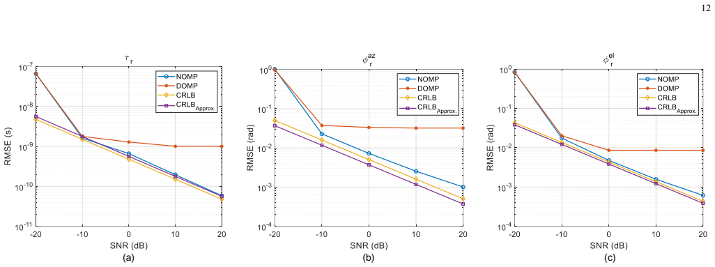
The central claim is that the channel difference between two closely spaced instants with different RIS phase configurations isolates the RIS reflection: $\mathbf{H}_s[i]=\mathbf{H}_s[i-1]$, so $\mathbf{s}_{i,i-1}=(\mathbf{H}_r[i]-\mathbf{H}_r[i-1])\mathbf{f}x+\mathbf{w}_{i,i-1}$. Fisher information theory then yields a closed-form position error bound in 3D, expressed as an information ellipsoid whose axes are range information intensity, proportional to bandwidth squared, and angle information intensities, proportional to array aperture divided by distance squared. The paper claims that increasing observation time multiplies the equivalent Fisher information by $(T-1)$ under optimized phases, that extra receivers always weakly decrease the Cram\'er-Rao lower bound, that receivers with self-positioning errors still help unless their error is very large, and that the resulting millimeter-level position error bound supports detection probabilities near 100 percent for millimeter deformations under adequate time, bandwidth, and RIS size. The numerical validation with a Newtonized orthogonal matching pursuit estimator shows delay and angle root-mean-square error close to the derived CRLB.
Load-bearing premise
The load-bearing premise is that the background multipath channel is identical at the two closely spaced measurement instants, as stated in Eq. (6), so subtracting adjacent measurements removes all non-RIS reflections; if any scatterer moves or changes between instants, its residual becomes unmodeled clutter that can swamp millimeter-level detection.
Editorial extensions
If this is right
- If the central claim holds, a 16x16 RIS with an 8x8 receive array can reach a 100 percent detection probability for millimeter-level deformation by integrating over one 20 ms radio frame with 2240 OFDM symbols.
- Cooperative receivers with meter-level self-positioning errors do not degrade the network CRLB, and three receivers with millimeter-level self-positioning errors match a perfectly positioned receiver in the simulated setup.
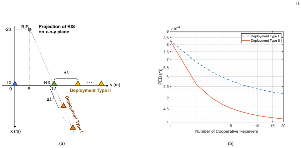
- Deployment Type II, with cooperative receivers spread along the positive y-axis, gives a smaller PEB than Deployment Type I because of spatial diversity, making receiver placement a design lever.
- RIS phases optimized at installation remain robust to sub-meter RIS position shifts and to a few degrees of orientation change, so frequent reconfiguration may be unnecessary.
- Performance improves monotonically with observation time, receiver count, bandwidth, antenna count, and RIS size under the model.
Reading between the lines
- The paper leaves implicit that the same differencing idea could monitor rotation, torsion, and bending by placing several RISs on one structure and combining their estimated displacements, since the single-RIS framework only detects translation.
- A testable extension is to apply the method to a real bridge or high-rise with an independent laser or GNSS reference and deliberately create moving background scatterers, because the static-scatterer assumption in Eq. (6) is the first premise likely to break at millimeter accuracy.
- An unproven corner is Theorem 5's assumption that the receiver position-error covariance is diagonal in the target-centric basis $\mathbf{U}$; a numerical test with a Cartesian-diagonal $\mathbf{Q}_R$ that is not diagonal in $\mathbf{U}$ would show how much optimism remains.
Editorial analysis
A structured set of objections, weighed in public.
Referee Report
Summary. This paper proposes an RIS-aided cooperative ISAC framework for structural health monitoring. The key idea is to mount an RIS on a possibly deformable structure, alternate its phase configuration between two closely spaced observation instants, and subtract the received signals so that the static background multipath channel cancels. The remaining differential signal is then used to estimate the RIS position via a Fisher information analysis. The authors derive closed-form FIM and EFIM expressions, extend them to temporal accumulation, multiple cooperative receivers, and receivers with self-positioning errors, and build a Bayesian/Wald detection model for structural state identification. Numerical results validate the CRLB through the NOMP algorithm and study the PEB and detection probability as functions of bandwidth, array size, RIS size, observation time, and cooperative node geometry.
Significance. If the result holds, the paper is a useful contribution: it translates SHM accuracy requirements into concrete network design parameters and provides analytic expressions for the PEB of an RIS reference point as a function of bandwidth, antenna count, RIS size, observation time, node placement, and receiver position uncertainty. The ideal-case EFIM derivation follows standard CRLB machinery, and the NOMP simulation in Section V-C supports the single-configuration CRLB expressions. The paper also makes falsifiable predictions (e.g., PEB decreases with T, K, M, and B) and compares concrete deployment strategies. However, the central claim of millimeter-level deformation detection is not yet robust: the RIS gain expression appears to contain a factor-M^2 algebraic error, the static-background assumption that enables the whole differential measurement is not bounded or stress-tested, and the detection model has dimensional inconsistencies. These issues are load-bearing for the central claim, but they appear correctable within the manuscript's scope.
major comments (5)
- [Section III-A, Eqs. (19a)-(21)] The text states that with the optimized RIS phases, beta_{**} = 4M^4. Direct evaluation of Eq. (19a) with unit-modulus steering vectors and |Omega[i]-Omega[i-1]|_mm = 2 gives beta_{**} = 4M^2, because each scalar factor in (19a) is a sum of M terms of magnitude at most 2, so the product has magnitude at most (2M)^2 = 4M^2. The asserted value 4M^4 overestimates the RIS contribution by a factor of M^2. Since the per-antenna SNR in Eq. (20) and all subsequent FIM entries, including (24), (26), (28), (30), and (32), inherit this factor, the reported PEB values in Figs. 5-9 and the detection probabilities in Figs. 11-12 are optimistically biased. This algebraic error must be corrected and the simulations rerun before the millimeter-level claim can be accepted.
- [Section II-A, Eq. (6)] The central cancellation H_s[i] = H_s[i-1] is assumed but never bounded. In a real deployment, the two observation instants are separated by at least one RIS phase switch, and vehicles, pedestrians, foliage, wind, or thermal drift can alter the background scatterer channel. The residual Delta H_s = H_s[i] - H_s[i-1] enters the differential signal in Eq. (10) as unmodeled clutter, and at the claimed millimeter accuracy even a weak residual scatterer can produce a bias comparable to the deformation signal. The numerical validation in Section V-C uses synthetic data generated under exactly the same static-background model, so it cannot detect a violation of (6). The authors should either model Delta H_s in the FIM or provide an explicit condition (e.g., a bound on residual scatterer power or a coherence-time requirement) under which the millimeter-level PEB claim remains valid.
- [Section IV-C, Eq. (61)] The step Q_R^{-1} = U tilde-Q_R^{-1} U^H assumes that the receiver position-error covariance is diagonal in the target-centric U basis. For the diagonal Cartesian covariance stated in Eq. (59), this is generally false: the columns of U are geometry-dependent direction vectors (u_tau, u_phi_az, u_phi_el) and are not eigenvectors of an arbitrary diagonal Q_R. Consequently, Theorem 5 and Corollary 6 do not hold for arbitrary diagonal Q_R. The authors should either derive the EFIM for a general Q_R, or state and justify an additional assumption such as isotropic error (Q_R = qI), or show that the diagonalization in the U basis is a conservative bound.
- [Section III-C, Eqs. (42)-(44)] The detection model is dimensionally inconsistent. The statistic d(hat-r) = (hat-r - r0)^T F(hat-r)(hat-r - r0) is dimensionless because F has units m^{-2}, yet the threshold kappa is stated in millimeters and the assumed variances sigma_p^2 have units m^2. Under H0, the exact distribution of d is a chi-squared distribution with three degrees of freedom (for a known FIM), not a zero-mean Gaussian. This undermines the quantitative detection-probability results in Figs. 11-12. The authors should define a physical displacement statistic with proper units, or use the correct noncentral chi-squared / quadratic-form distribution for the Wald test, and then recompute the detection probabilities.
- [Section IV-B, Corollary 4] Corollary 4 relies on the EFIM being a sum of positive semidefinite rank-one terms for each receiver. This is valid if each receiver's FIM is expressed in the same global coordinate basis, which the paper does implicitly. However, the proof in Eq. (55) uses an EFIM decomposition in which the U_k matrices differ per receiver; the inequality F[1:K+1] >= F[1:K] follows as stated, but the authors should clarify that the U_k columns are expressed in a common coordinate frame to avoid an apparent basis mismatch.
minor comments (5)
- [Section III-A, Eq. (21)] The beamforming vector is written as f = a_H^T(...) in the text; it should be f = a_T(theta_az, theta_el), a column vector, with the Hermitian transpose used only in the alignment argument.
- [Section III-A, Eq. (19a)] The notation beta_{**} is undefined; the subscripts should be tied to the parameter pair (e.g., beta_{tau_r tau_r}, beta_{phi_az phi_az}) for readability.
- [Appendix C, Eq. (86)] There is a typo in 'Acoording' in the proof of the non-negativity result; the sentence should read 'According'.
- [Section V-C, Fig. 10] The label 'CRLBApprox.' is missing a space and could be typeset as 'CRLB Approx.'; also, the figure caption should state explicitly which curves are which, since the legend is small.
- [Section II-A, Eq. (2)] The channel model in Eq. (2) includes the RIS phase matrix Omega[i] as an M x M diagonal matrix premultiplying the RIS steering vectors; the dimensions of the product are not immediately obvious, and a short dimension-check or block diagram would help the reader verify the M-scaling of the final expressions.
Circularity Check
No significant circularity: the CRLB/EFIM and detection-probability results are derived from the stated signal model, with no fitted parameter or self-citation chain forcing the millimeter-level conclusion.
full rationale
The derivation chain is self-contained. The received-signal model (1)-(10) defines the measurement; Eqs. (11)-(17) define the FIM, CRLB, and PEB from derivatives of that model. The closed-form FIM elements (24)-(32), Theorem 1's EFIM (37), and Corollaries 2-6 are algebraic consequences of the model and of external EFIM results [29], [30], [32], [34]; none of those citations is authored by the present paper's authors, and none smuggles in the millimeter-level conclusion. The self-citations ([1], [15]) point only to earlier WOCC material and a prior ISAC-SLAM method; neither is load-bearing for the PEB. The Bayesian detection model in Section III-C deliberately defines the likelihood variances through the PEB, so the detection-probability curves in Figs. 11-12 are derived consequences of the PEB rather than independent empirical predictions; this is a modeling and consistency check, not a fitted-parameter circularity. Similarly, the NOMP simulation in Section V-C uses data generated from the same signal model and therefore validates the algebra of the EFIM, not the physical assumptions. The main caveat, Eq. (6) H_s[i]=H_s[i-1], is a stated stationarity premise; an unmodeled violation would bias the estimates, but assuming a premise is not circular reasoning.
Assumptions & free parameters
free parameters (1)
- per-antenna SNR =
20 dB (simulation parameter)
assumptions (5)
- domain assumption Static scatterer channel between adjacent observation instants: H_s[i] = H_s[i-1] (Eq. 6)
- domain assumption Far-field point-target model for the RIS, with known initial position and orientation (Section II-A)
- standard math Block-diagonal structure of the channel-parameter FIM, FB = 0 (Section III-B, Eq. (34))
- ad hoc to paper Receiver position-error covariance Q_R is diagonal in the U basis (Section IV-C, Eq. (61))
- domain assumption Gaussian likelihoods for the Wald statistic d(r_hat) under both hypotheses (Section III-C)
Cite this review
Pith. "Pith review of RIS-Aided Cooperative ISAC Networks for Structural Health Monitoring." pith.science (2026). https://pith.science/paper/26E6OHSV
@misc{pith2026250702731,
  author       = {Pith},
  title        = {Pith review of: RIS-Aided Cooperative ISAC Networks for Structural Health Monitoring},
  year         = {2026},
  howpublished = {\url{https://pith.science/paper/26E6OHSV}},
  note         = {Machine review of arXiv:2507.02731}
}
read the original abstract
Integrated sensing and communication (ISAC) is a key feature of future cellular systems, enabling applications such as intruder detection, monitoring, and tracking using the same infrastructure. However, its potential for structural health monitoring (SHM), which requires the detection of slow and subtle structural changes, remains largely unexplored due to challenges such as multipath interference and the need for ultra-high sensing precision. This study introduces a novel theoretical framework for SHM via ISAC by leveraging reconfigurable intelligent surfaces (RIS) as reference points in collaboration with base stations and users. By dynamically adjusting RIS phases to generate distinct radio signals that suppress background multipath interference, measurement accuracy at these reference points is enhanced. We theoretically analyze RIS-aided collaborative sensing in three-dimensional cellular networks using Fisher information theory, demonstrating how increasing observation time, incorporating additional receivers (even with self-positioning errors), optimizing RIS phases, and refining collaborative node selection can reduce the position error bound to meet SHM's stringent accuracy requirements. Furthermore, we develop a Bayesian inference model to identify structural states and validate damage detection probabilities. Both theoretical and numerical analyses confirm ISAC's capability for millimeter-level deformation detection, highlighting its potential for high-precision SHM applications.
Figures
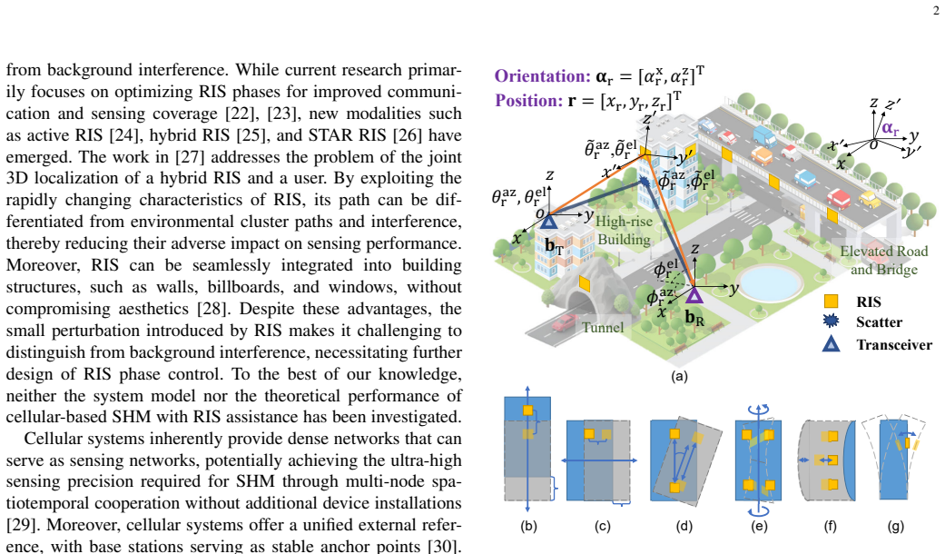


Figures from the paper (7 more)





Reference graph
Works this paper leans on
-
[1]
Application of integrated sensing and communication in structural health monitoring,
J. Yang, C.-K. Wen, and S. Jin, “Application of integrated sensing and communication in structural health monitoring,” in Proc. 2024 33rd Wireless Opt. Commun. Conf. (WOCC) , 2024, pp. 128–133. 15 Fe(r) = U Fτr τr c2 0 0 0 Fϕazr ϕazr c2(τr−τtr)2 cos2 ϕelr − Fϕelr ϕazr Fϕazr ϕelr c2(τr−τtr)2 cos2 ϕelr Fϕelr ϕelr 0 0 0 Fϕelr ϕelr c2(τr−τtr)2 − Fϕazr ...
work page 2024
-
[2]
Structural health monitoring using wireless sensor networks: A comprehensive survey,
A. B. Noel et al. , “Structural health monitoring using wireless sensor networks: A comprehensive survey,” IEEE Commun. Surveys & Tutori- als, vol. 19, no. 3, pp. 1403–1423, 2017
work page 2017
-
[3]
MIMO-SAR interferometric measurements for structural monitoring: Accuracy and limitations,
A. Baumann-Ouyang et al., “MIMO-SAR interferometric measurements for structural monitoring: Accuracy and limitations,” Remote Sens. , vol. 13, no. 21, pp. 4290–4309, 2021
work page 2021
-
[4]
An overview of multi-modal sensing systems and the potential of ISAC technologies in SHM,
Z. Zhu et al. , “An overview of multi-modal sensing systems and the potential of ISAC technologies in SHM,” Phys. Commun. , vol. 69, p. 102614, 2025
work page 2025
-
[5]
Integrated sensing and communications: Toward dual- functional wireless networks for 6G and beyond,
F. Liu et al. , “Integrated sensing and communications: Toward dual- functional wireless networks for 6G and beyond,” IEEE J. Sel. Areas Commun., vol. 40, no. 6, pp. 1728–1767, 2022
2022
-
[6]
Integrated sensing and communications: Recent advances and ten open challenges,
S. Lu et al., “Integrated sensing and communications: Recent advances and ten open challenges,” IEEE Internet Things J. , vol. 11, no. 11, pp. 19 094–19 120, 2024
work page 2024
-
[7]
6G positioning and sensing through the lens of sustainability, inclusiveness, and trustworthiness,
H. Wymeersch et al. , “6G positioning and sensing through the lens of sustainability, inclusiveness, and trustworthiness,” IEEE Wireless Commun., vol. 32, no. 1, pp. 68–75, 2025
work page 2025
-
[8]
Integrated sensing and communication: 3GPP standardiza- tion progress,
H. Li et al., “Integrated sensing and communication: 3GPP standardiza- tion progress,” in proc. 21st Int. Symp. Model. Optim. Mobile, Ad Hoc, Wireless Netw. (WiOpt), 2023, pp. 1–7
work page 2023
Show all 37 references
-
[9]
Feasibility study on integrated sensing and communication,
3GPP, “Feasibility study on integrated sensing and communication,” Technical Report 3GPP TR 22.837 V19.4.0 (2024-06), 2024
2024
-
[10]
Distributed intelligent integrated sensing and communications: The 6G-DISAC approach,
E. C. Strinati et al. , “Distributed intelligent integrated sensing and communications: The 6G-DISAC approach,” in Proc. 2024 Joint Eur. Conf. Networks Commun. & 6G Summit (EuCNC/6G Summit) , 2024, pp. 392–397
2024
-
[11]
Cooperative ISAC networks: Performance analysis, scaling laws and optimization,
K. Meng et al. , “Cooperative ISAC networks: Performance analysis, scaling laws and optimization,” IEEE Trans. Wireless Commun., pp. 1– 1, 2024
2024
-
[12]
Integrated sensing and communication enabled multiple base stations cooperative sensing towards 6G,
Z. Wei et al., “Integrated sensing and communication enabled multiple base stations cooperative sensing towards 6G,” IEEE Network, vol. 38, no. 4, pp. 207–215, 2024
2024
-
[13]
Deep cooperation in ISAC system: Resource, node and infras- tructure perspectives,
——, “Deep cooperation in ISAC system: Resource, node and infras- tructure perspectives,” IEEE Internet Things Mag. , vol. 7, no. 6, pp. 118–125, 2024
2024
-
[14]
Real-time bayesian neural networks for 6G cooperative positioning and tracking,
B. C. Tedeschini et al. , “Real-time bayesian neural networks for 6G cooperative positioning and tracking,” IEEE J. Sel. Areas Commun. , vol. 42, no. 9, pp. 2322–2338, 2024
2024
-
[15]
Hybrid active and passive sensing for SLAM in wireless communication systems,
J. Yang, C.-K. Wen, and S. Jin, “Hybrid active and passive sensing for SLAM in wireless communication systems,” IEEE J. Sel. Areas Commun., vol. 40, no. 7, pp. 2146–2163, 2022
2022
-
[16]
Joint localization, synchronization and mapping via phase-coherent distributed arrays,
A. Fascista et al., “Joint localization, synchronization and mapping via phase-coherent distributed arrays,” IEEE J. Sel. Topics Signal Process. , pp. 1–16, 2025
2025
-
[17]
GNSS-assisted low-cost vision-based observation system for deformation monitoring,
R. Shults et al. , “GNSS-assisted low-cost vision-based observation system for deformation monitoring,” Appl. Sci., vol. 13, no. 5, pp. 2813– 2848, 2023
2023
-
[18]
Deformations and displacements of buildings and building el- ements at serviceability limit states,
ISO, “Deformations and displacements of buildings and building el- ements at serviceability limit states,” Geneva, Switzerland, Technical Report ISO/TR 4553:2022, 2022
2022
-
[19]
Smart radio environments empowered by reconfig- urable intelligent surfaces: How it works, state of research, and the road ahead,
M. Di Renzo et al., “Smart radio environments empowered by reconfig- urable intelligent surfaces: How it works, state of research, and the road ahead,” IEEE J. Sel. Areas Commun. , vol. 38, no. 11, pp. 2450–2525, 2020
2020
-
[20]
Wireless communications with reconfigurable intelligent surface: Path loss modeling and experimental measurement,
W. Tang et al., “Wireless communications with reconfigurable intelligent surface: Path loss modeling and experimental measurement,” IEEE Trans. Wireless Commun., vol. 20, no. 1, pp. 421–439, 2021
2021
-
[21]
Reconfigurable intelligent surfaces: Principles and op- portunities,
Y . Liu et al. , “Reconfigurable intelligent surfaces: Principles and op- portunities,” IEEE Commun. Surveys & Tutorials , vol. 23, no. 3, pp. 1546–1577, 2021
2021
-
[22]
IRS aided millimeter-wave sensing and communication: Beam scanning, beam splitting, and performance analysis,
R. Li et al. , “IRS aided millimeter-wave sensing and communication: Beam scanning, beam splitting, and performance analysis,” IEEE Trans. Wireless Commun., vol. 23, no. 12, pp. 19 713–19 727, 2024
2024
-
[23]
Joint waveform and beamforming design for RIS-aided ISAC systems,
K. Zhong et al., “Joint waveform and beamforming design for RIS-aided ISAC systems,” IEEE Signal Process. Lett., vol. 30, pp. 165–169, 2023
2023
-
[24]
Active RIS vs. passive RIS: Which will prevail in 6G?
Z. Zhang et al., “Active RIS vs. passive RIS: Which will prevail in 6G?” IEEE Trans. Commun. , vol. 71, no. 3, pp. 1707–1725, 2023
2023
-
[25]
Hybrid reconfigurable intelligent surface- enabled enhanced reflection modulation,
A. T. Dogukan et al. , “Hybrid reconfigurable intelligent surface- enabled enhanced reflection modulation,” IEEE Trans. Wireless Com- mun., vol. 23, no. 12, pp. 18 929–18 939, 2024
2024
-
[26]
Simultaneously transmitting and reflecting (STAR) RIS aided wireless communications,
X. Mu et al. , “Simultaneously transmitting and reflecting (STAR) RIS aided wireless communications,” IEEE Trans. Wireless Commun. , vol. 21, no. 5, pp. 3083–3098, 2022
2022
-
[27]
Joint 3D user and 6D hybrid reconfigurable intelligent surface localization,
R. Ghazalian et al. , “Joint 3D user and 6D hybrid reconfigurable intelligent surface localization,” IEEE Trans. Veh. Technol. , vol. 73, no. 10, pp. 15 302–15 317, 2024
2024
-
[28]
Information metamaterials and metasurfaces,
T. J. Cui, S. Liu, and L. Zhang, “Information metamaterials and metasurfaces,” J. Mater. Chem. C, vol. 5, no. 15, pp. 3644–3668, 2017
2017
-
[29]
Joint communication and localization in millimeter wave networks,
G. Kwon et al. , “Joint communication and localization in millimeter wave networks,” IEEE J. Sel. Topics Signal Process. , vol. 15, no. 6, pp. 1439–1454, 2021
2021
-
[30]
Error bounds for uplink and downlink 3D localization in 5G millimeter wave systems,
Z. Abu-Shaban et al. , “Error bounds for uplink and downlink 3D localization in 5G millimeter wave systems,” IEEE Trans. Wireless Commun., vol. 17, no. 8, pp. 4939–4954, 2018
2018
-
[31]
Cooperative localization in wireless networks,
H. Wymeersch, J. Lien, and M. Z. Win, “Cooperative localization in wireless networks,” Proc. IEEE, vol. 97, no. 2, pp. 427–450, 2009
2009
-
[32]
Fundamental limits of wideband localization — Part I: A general framework,
Y . Shen and M. Z. Win, “Fundamental limits of wideband localization — Part I: A general framework,” IEEE Trans. Inf. Theory , vol. 56, no. 10, pp. 4956–4980, 2010
2010
-
[33]
Fundamental limits of wideband localization — Part II: Cooperative networks,
Y . Shen, H. Wymeersch, and M. Z. Win, “Fundamental limits of wideband localization — Part II: Cooperative networks,” IEEE Trans. Inf. Theory, vol. 56, no. 10, pp. 4981–5000, 2010
2010
-
[34]
A theoretical foundation of network localization and navigation,
M. Z. Win, Y . Shen, and W. Dai, “A theoretical foundation of network localization and navigation,” Proc. IEEE, vol. 106, no. 7, pp. 1136–1165, 2018
2018
-
[35]
Intelligent adaptive metasurface in complex wireless environments,
H. Q. Yang et al., “Intelligent adaptive metasurface in complex wireless environments,” arXiv preprint arXiv:2411.08538 , 2024
2024 arXiv
-
[36]
Expected utility theory for monitoring-based decision-making,
C. Cappello, D. Zonta, and B. Gli ˇsi´c, “Expected utility theory for monitoring-based decision-making,” Proc. IEEE , vol. 104, no. 8, pp. 1647–1661, 2016
2016
-
[37]
Newtonized orthog- onal matching pursuit: Frequency estimation over the continuum,
B. Mamandipoor, D. Ramasamy, and U. Madhow, “Newtonized orthog- onal matching pursuit: Frequency estimation over the continuum,” IEEE Trans. Signal Process., vol. 64, no. 19, pp. 5066–5081, 2016
2016
Reviewed August 6, 2026 · model on record in the stance chip above.
Discussion (0). Continue with ORCID to comment.