REVIEW 3 major objections 4 minor 21 references
A Robust COTS Objective for Diffraction-Limited, High-NA, Long Front Working Distance Imaging
T0 review · 3 major / 4 minor · reviewed 2026-08-06 · deepseek-v4-flash
Pith's one-line read Five off-the-shelf singlet lenses deliver diffraction-limited 0.87 µm imaging from 61 mm away.
desk verdict A genuinely useful engineering demonstration: an all-COTS five-singlet objective that directly projects diffraction-limited images with long working distance and high NA, verified at three wavelengths, but the 'robust' claim outruns the evidence because there is no tolerance analysis. read the letter →
The pith
A machine-rendered reading of the paper's core claim, the machinery that carries it, and where it could break.
The reading
What carries the argument
The design is carried by an iterative optimization process that starts from a three-lens meniscus/plano-convex/plano-concave group, adds singlets until the RMS spot size falls below the Airy-disk radius, and then replaces each element with a closely matching COTS singlet while re-optimizing. The first meniscus lens maintains the required NA while limiting spherical aberration, the positive lenses converge the image, and a final plano-concave element compensates for residual aberration. Precision-machined brass spacer rings set the inter-lens distances and align the stack. The key simplification is direct projection of the image onto the back focal plane, which removes the separate refocusing stage and its associated bulk and effective-NA restriction.
What would settle it
Assemble a second copy of the objective from the same part numbers with the same 10 µm spacer-ring machining tolerance and measure Strehl ratio or USAF resolution at 375, 397, and 866 nm and at both ends of the 46 mm length range; if any configuration fails the diffraction-limited criterion (for example, cannot resolve the 0.87 µm target at 397 nm), the claimed robustness would be contradicted.
Extended reading notes
Core claim
The central claim is that spherical aberration from thick vacuum and cryostat windows at high NA can be corrected entirely with five off-the-shelf singlets arranged in a single lens group that converges light directly onto the back focal plane, eliminating the refocusing optics required by earlier COTS designs. The authors validate this with a concrete implementation: under 397 nm illumination, the objective resolves Group 9 Element 2 of a 1951 USAF target corresponding to 0.87 µm line widths, matching the diffraction-limited Airy radius, while the measured Strehl-based field of view and magnification agree with simulation. They further show that only a small adjustment of the gap between the first lens and the window keeps the system diffraction limited across 375–866 nm and across a −14 mm to +32 mm change in total length, with all lenses and inter-lens spacings fixed.
Load-bearing premise
The robustness claims rest on the assumption that the as-built COTS singlets and machined brass spacer rings reproduce the Zemax prescription within tolerances that keep the system diffraction limited, but the paper reports only 10 µm machining tolerances for the spacer rings and gives no Monte Carlo tolerance or sensitivity analysis, while experimental checks cover only a few wavelengths and total-length points.
Editorial extensions
If this is right
- Researchers can reproduce the reported 61 mm working distance, 0.30 NA objective by ordering the listed COTS singlets and machining spacer rings to the published table.
- The same lens stack, with only a small change in the front gap, is simulated to remain diffraction limited at wavelengths for other atomic species (Yb⁺, Sr⁺, Ba⁺, Rb, Cs) at NA 0.35–0.37.
- A 46 mm tolerance on total length means the camera and objective do not require precise placement, easing integration into vacuum and cryostat systems.
- The pinhole-scan Strehl method provides a quantitative, repeatable field-of-view measurement that can be applied to other imaging systems.
Reading between the lines
- Because the design uses standard parts, the same iterative optimization could be adapted quickly to other working distances and window configurations by substituting different COTS catalogs.
- A natural stress test would be to add a Monte Carlo tolerance analysis on lens curvatures, thicknesses, and spacer lengths, since the paper's robustness claim currently rests on simulation plus a limited set of experimental points.
- The single-group direct-focusing scheme may also reduce the number of optical surfaces and stray-light paths compared to two-stage designs, though the paper does not quantify stray light.
- The field-of-view method's dependence on an experimentally calibrated pinhole diameter could be extended to infer wavefront quality across the full aperture, not just on-axis.
Signed reviews
Editorial analysis
A structured set of objections, weighed in public.
Referee Report
Summary. The manuscript presents a compound imaging objective built from five commercial fused-silica singlet lenses in a single lens group that images directly onto the back focal plane, without separate collimation/refocusing optics. The example system has a 61 mm front working distance, a clipped NA of 0.30, and a simulated/measured resolution of 0.87 µm at 397 nm. The authors report USAF target images at 375, 397, and 866 nm, images at two extremes of a 46 mm total-length variation, and a pinhole-scan method for measuring the field of view. The stated central claims are: diffraction-limited performance across 375–866 nm, robustness to a 46 mm total-length change, a 540 µm FOV at 397 nm, and an experimentally validated FOV-measurement technique.
Significance. If fully substantiated, the design would be a practical, low-cost, all-singlet alternative to custom aspheric or multi-group objectives for AMO and QIS experiments that require imaging through thick vacuum/cryostat windows at long working distance. The paper's concrete strengths are the clear step-by-step design methodology, the detailed optical prescription in Table 1, the experimental demonstrations at three wavelengths and two total-length extremes, and the quantitative FOV-mapping procedure. The main gaps are the absence of a tolerance analysis for the COTS lenses and the visual, non-quantitative basis for the 'diffraction-limited' claim. Both are fixable within the manuscript's scope, so the work is suitable for major revision rather than rejection.
major comments (3)
- [Section 3, Table 1] The central 'robust' claim is not supported by a tolerance analysis. The only tolerance mentioned is the 10 µm machining tolerance for the brass spacer rings; there is no Monte Carlo or sensitivity study over the five COTS lenses' manufacturing tolerances (surface radius, center thickness, wedge, refractive index, surface irregularity) or over assembly errors. At NA=0.30 with 13.4 mm of fused-silica windows, the design balances spherical aberration among five catalog surfaces, so small perturbations can plausibly shift the aberration balance. The experimental validation covers one assembled copy at a few wavelengths and total lengths and cannot bound the distribution over lens lots. Please add a Zemax tolerance analysis (e.g., Monte Carlo with vendor tolerances) and report the predicted Strehl distribution; if that is not feasible, explicitly limit the robustness claim to the demonstrated prototype.
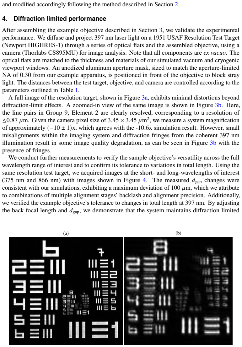
- [Section 4, Figs. 3-5] The claim 'experimentally verify diffraction-limited resolution' is inferred solely from visual inspection of USAF target images ('clearly resolved' Group 9 Element 2). Resolving line pairs at 0.87 µm is strong evidence of good image quality, but it is not a quantitative measurement of diffraction-limited performance; contrast at the resolution limit, MTF/CTF, or a measured PSF/Strehl ratio are needed to support the stronger claim. The images in Fig. 3b show visible diffraction fringes and possible degradation, and no error bars are provided for the resolution. Please add a contrast transfer function measurement or an equivalent quantitative metric, or qualify the claim accordingly.
- [Section 5, Fig. 6] The FOV measurement is partly self-referential. The ideal reference image is generated with the POP module from the same Zemax model whose field behavior is under test, and the pinhole diameter is calibrated from the objective's own Airy pattern. Consequently, agreement between the measured Strehl contour and the simulated FOV (red circle in Fig. 6c) does not provide an independent validation of the model. In particular, if the POP reference includes the model's field-dependent aberrations, the measured ratio would be approximately flat even for a system that exactly follows the model, making it insensitive to the very aberrations that define the FOV. Please state clearly whether the POP reference is on-axis only, and consider an independent reference (e.g., an ideal Airy disk at the measured NA, or a pinhole diameter verified by SEM) to break the circularity.
minor comments (4)
- [Throughout] Several typos and grammatical errors should be corrected: 'a a' in the Conclusion, 'Elemenet' in the Fig. 4 caption, 'Veiwport' in the Table 2 caption, and missing closing parentheses after 'Figure 6b' and 'dashed grey lines' in Section 5.
- [Ref. [21]] The statement 'Documents are available upon request' is not sufficient for reproducibility; please archive the Zemax file or provide it as supplementary material.
- [Abstract and Introduction] The phrase 'all-COTS' could be misread as applying to the entire assembly; only the optical lenses are COTS, while the brass spacer rings and aperture mask are custom-machined. Please clarify this in the abstract or introduction.
- [Abstract and Conclusion] The experimental wavelength coverage is 375, 397, and 866 nm; intermediate wavelengths between these points are demonstrated only in simulation. Please word the abstract and conclusion to distinguish measured wavelengths from simulated ones.
Circularity Check
No significant circularity: central resolution and robustness claims are externally benchmarked, and the FOV method uses a diffraction-limited POP reference, not a circular reduction.
full rationale
The paper's central claims are supported by external benchmarks: the 0.87 um resolution is verified with a 1951 USAF target (Group 9 Element 2), and wavelength/total-length robustness is verified at discrete experimental points (375 nm, 866 nm, and total lengths of approximately 714 mm and 760 mm). The design methodology is a forward Zemax optimization loop that minimizes RMS wavefront error; no parameter fitted to a subset of data is renamed as a prediction. The FOV measurement in Section 5 uses a POP ideal reference generated from the same optical design, which is a legitimate point to scrutinize, but the reference is the diffraction-limited Airy disk at 397 nm for NA=0.30, convolved with the pinhole; it is not the design's predicted off-axis FOV. The pinhole diameter (0.88(3) um) is calibrated using the objective's PSF but is cross-checked against manufacturing tolerances, and the resulting Strehl map is an independent experimental dataset compared with, not derived from, the simulated FOV contour. The robustness claim lacks a Monte Carlo tolerance analysis over COTS lens manufacturing variations, but this is a missing-support concern, not circularity: it does not reduce a predicted quantity to an input by construction.
Assumptions & free parameters
free parameters (4)
- d_gap (gap from last window to first lens) =
-0.4 mm to +2.9 mm relative to design at 375-866 nm; 4.3-8.1 mm in Table 2
- Inter-lens air gaps and back focal length =
Table 1; nominal BFL 613 mm, 46 mm adjustable range
- Aperture mask diameter for NA 0.30 =
NA 0.30 (30 mm aperture at cryostat window)
- Reproduced pinhole diameter for FOV reference =
0.88(3) um
assumptions (5)
- domain assumption Zemax ray tracing correctly models diffraction and aberrations for the COTS design
- domain assumption Catalog lens prescriptions and fused silica material data match the delivered lenses
- domain assumption Optical flats used in the experiment replicate the simulated vacuum and cryostat viewports
- domain assumption The USAF target resolving a given group/element is sufficient evidence of diffraction-limited resolution
- domain assumption Strehl ratio >= 0.8 defines the FOV boundary
Cite this review
Pith. "Pith review of A Robust COTS Objective for Diffraction-Limited, High-NA, Long Front Working Distance Imaging." pith.science (2026). https://pith.science/paper/NDNDE6YC
@misc{pith2026250715786,
  author       = {Pith},
  title        = {Pith review of: A Robust COTS Objective for Diffraction-Limited, High-NA, Long Front Working Distance Imaging},
  year         = {2026},
  howpublished = {\url{https://pith.science/paper/NDNDE6YC}},
  note         = {Machine review of arXiv:2507.15786}
}
abstract
We present a robust objective lens optimized for applications requiring both high numerical aperture (NA) and long front working distance imaging comprised of all commercial-off-the-shelf (COTS) singlet lenses. Unlike traditional designs that require separate collimation and refocusing stages, our approach directly converges imaged light to the back focal plane using a single lens group. Our configuration corrects spherical aberrations and efficiently collects light to achieve diffraction-limited performance across a wide range of wavelengths while simplifying alignment and assembly. Using this approach, we design and construct an example objective lens that features a long front working distance of 61 mm and a clipped NA of 0.30 (limited by an aperture in our experimental setup). We experimentally verify that it achieves monochromatic diffraction-limited resolution at wavelengths from 375 nm to 866 nm without requiring replacement of the lenses or changing the inter-lens spacings, and its performance remains robust across a 46 mm range variation in total length (by adjusting mainly the back working distances). Additionally, we develop a quantitative method to measure the field of view (FOV) using an experimentally-calibrated pinhole target. Under 397 nm illumination (i.e. from $^{40}$Ca$^+$ ion fluorescence), the objective achieves a resolution of 0.87 $\mu$m with a 540 $\mu$m FOV. This robust, all-COTS, and versatile design is well-suited for a broad range of experiments, supporting high-precision measurements and exploring quantum phenomena.
Figures


Figures from the paper (3 more)


Reference graph
Works this paper leans on
-
[1]
A quantum gas microscope for detecting single atoms in a hubbard-regime optical lattice,
W. S. Bakr, J. I. Gillen, A. Peng,et al., “A quantum gas microscope for detecting single atoms in a hubbard-regime optical lattice,” Nature462, 74–77 (2009)
work page 2009
-
[2]
Entangled states of trapped atomic ions,
R. Blatt and D. Wineland, “Entangled states of trapped atomic ions,” Nature453, 1008–1015 (2008)
work page 2008
-
[3]
Optomechanics with levitated particles,
J. Millen, T. S. Monteiro, R. Pettit, and A. N. Vamivakas, “Optomechanics with levitated particles,” Reports on Prog. Phys. 83, 026401 (2020)
work page 2020
-
[4]
Cryogenic trapped-ion system for large scale quantum simulation,
G. Pagano, P. W. Hess, H. B. Kaplan,et al., “Cryogenic trapped-ion system for large scale quantum simulation,” Quantum Sci. Technol.4, 014004 (2018)
work page 2018
-
[5]
Collecting more than half the fluorescence photons from a single ion,
R. Maiwald, A. Golla, M. Fischer,et al., “Collecting more than half the fluorescence photons from a single ion,” Phys. Rev. A86, 043431 (2012)
work page 2012
-
[6]
Note: Single ion imaging and fluorescence collection with a parabolic mirror trap,
C.-K. Chou, C. Auchter, J. Lilieholm,et al., “Note: Single ion imaging and fluorescence collection with a parabolic mirror trap,” Rev. Sci. Instruments88, 086101 (2017)
work page 2017
-
[7]
ThePanopticondevice: AnintegratedPaul-trap–hemispherical mirror system for quantum optics,
G.Araneda,G.Cerchiari,D.B.Higginbottom, et al.,“ThePanopticondevice: AnintegratedPaul-trap–hemispherical mirror system for quantum optics,” Rev. Sci. Instruments91, 113201 (2020)
work page 2020
-
[9]
D.Coyne, LIGO Vacuum Compatile Materials List (LIGO-E960050-v13, 2014)
work page 2014
Show all 21 references
-
[10]
Highnumericalaperture(na =0.92)objectivelensforimagingandaddressing of cold atoms,
C.Robens,S.Brakhane,W.Alt, et al.,“Highnumericalaperture(na =0.92)objectivelensforimagingandaddressing of cold atoms,” Opt. Lett.42, 1043–1046 (2017)
2017
-
[11]
Ion trap with in-vacuum high numerical aperture imaging for a dual-species modular quantum computer,
A. L. Carter, J. O’Reilly, G. Toh,et al., “Ion trap with in-vacuum high numerical aperture imaging for a dual-species modular quantum computer,” Rev. Sci. Instruments95, 033201 (2024)
2024
-
[12]
Wavelength-scale imaging of trapped ions using a phase fresnel lens,
A. Jechow, E. W. Streed, B. G. Norton,et al., “Wavelength-scale imaging of trapped ions using a phase fresnel lens,” Opt. Lett.36, 1371–1373 (2011)
2011
-
[13]
An objective lens for efficient fluorescence detection of single atoms,
W. Alt, “An objective lens for efficient fluorescence detection of single atoms,” Optik113, 142–144 (2002)
2002
-
[14]
A versatile high resolution objective for imaging quantum gases,
L. M. Bennie, P. T. Starkey, M. Jasperse,et al., “A versatile high resolution objective for imaging quantum gases,” Opt. Express21, 9011–9016 (2013)
2013
-
[15]
Long working distance objective lenses for single atom trapping and imaging,
J. D. Pritchard, J. A. Isaacs, and M. Saffman, “Long working distance objective lenses for single atom trapping and imaging,” Rev. Sci. Instruments87, 073107 (2016)
2016
-
[16]
High-resolution ex vacuo objective for cold atom experiments,
X. Li, F. Zhou, M. Ke,et al., “High-resolution ex vacuo objective for cold atom experiments,” Appl. Opt.57, 7584–7590 (2018)
2018
-
[17]
High-numerical-apertureandlong-working-distanceobjectiveforsingle-atomexperiments,
S.Li,G.Li,W.Wu, et al.,“High-numerical-apertureandlong-working-distanceobjectiveforsingle-atomexperiments,” Rev. Sci. Instruments91, 043104 (2020)
2020
-
[18]
High-resolution adaptive imaging of a single atom,
J. D. Wong-Campos, K. G. Johnson, B. Neyenhuis,et al., “High-resolution adaptive imaging of a single atom,” Nat. Photonics 10, 606–610 (2016)
2016
-
[19]
Objective lenses for trapped ion experiments,
K. Silvan, “Objective lenses for trapped ion experiments,” Tech. rep. (2020)
2020
-
[20]
Accessed: May 29, 2025
Ansys Zemax,OpticStudio User Guide, Ansys (2025). Accessed: May 29, 2025
2025
-
[21]
Documents are available upon request
-
[22]
R. B. J. Rudolf Kingslake,Lens Design Fundamentals, Second Edition (Elsevier/Academic Press, 2010)
2010
Reviewed August 6, 2026 · model on record in the stance chip above.
Discussion (0). Continue with ORCID to comment.