REVIEW 4 major objections 6 minor 30 references
Time Domain Design of a Josephson Parametric Amplifier and Comparison with Input Output Theory
T0 review · 4 major / 6 minor · reviewed 2026-08-05 · deepseek-v4-flash
Pith's one-line read A time-domain circuit simulator is shown to reproduce the gain curves that quantum input–output theory predicts for a Josephson parametric amplifier.
desk verdict A useful time-domain JPA simulation workflow, but the quantum-to-classical comparison is under-documented enough that part of the agreement is built into the normalization. read the letter →
The pith
A machine-rendered reading of the paper's core claim, the machinery that carries it, and where it could break.
The reading
What carries the argument
The argument is carried by two parallel descriptions of the same device. On the quantum side, the JPA is a parallel nonlinear LC circuit whose Hamiltonian is quantized and expanded to quartic order, yielding a damped, driven Duffing-like quantum Langevin equation; its steady-state pump photon number N solves a cubic equation, and the signal gain follows from the frequency-domain solution of the linearized equation for a weak signal tone. On the classical side, the same circuit is represented by a Norton equivalent with a Josephson junction, driven by pump and signal current sources; the reflection coefficient S11 is computed from the input and output voltages after Fourier projection of the
What would settle it
A decisive test would be to compute the bifurcation threshold directly from the time-domain circuit simulation (by increasing pump power until the response jumps) and then compare the resulting gain curves with the quantum theory using that independently determined pcrit, rather than importing pcrit from the quantum side. If the curves no longer align on the same power axis, the reported agreement comes from the shared normalization rather than from the models themselves.
Extended reading notes
Core claim
On its own terms, the paper's central claim is that, provided the comparison is set up correctly, quantum input–output theory and Josephson circuit simulators are interchangeable descriptions of a JPA. The quantitative evidence is that the JoSIM gain curves for the degenerate signal mode, plotted against detuning normalized by the cavity linewidth, agree with the input-output theory curves of Figs. 3 and 4, apart from 'slight discrepancies' the authors attribute to the linearization of the quantum Langevin equation and the relatively low quality factor of the cavity. The paper does not claim the time-domain simulation is a substitute for the quantum description of added noise; it claims equi
Load-bearing premise
The comparison hinges on the circuit simulation and the quantum theory being given the same resonance frequency, linewidth, and critical pump power, and the paper does not show that the critical power for the circuit model is determined independently of the quantum result.
Editorial extensions
If this is right
- JPA designers can use open-source circuit simulators and optimizers to explore design parameters, replacing analytical quantum calculations.
- The method extends naturally to multi-junction, coupled, or impedance-engineered resonant circuits where input-output theory is harder to apply.
- The comparison provides a benchmark for checking whether a given circuit model in a time-domain simulator captures parametric amplification quantitatively.
- The gain–bandwidth trade-off and the 1 dB compression point can be obtained directly from the time-domain simulation at the operating point.
- The approach may accelerate the design cycle for quantum-limited amplifiers in scalable quantum computers.
Reading between the lines
- A stricter test of the interchangeability claim would compute pcrit from the circuit model itself (for example, by locating the bifurcation threshold in the time-domain simulation) rather than importing it from the quantum theory; if the two critical powers differ, the agreement of the normalized curves is at least partly a result of the normalization.
- The 0.36% discrepancy between JoSIM and the ODE45 solver reported in the appendix suggests the classical computations are internally consistent, but the paper's quantum-vs-classical comparison is made only on the shape of the gain curves, not on absolute pump power; a reader should interpret 'interchangeable' as 'equivalent after the same parameters and normalization are imposed.'
- Because the time-domain simulation includes the full Josephson nonlinearity rather than a quartic expansion, it could be used to test predictions beyond the RWA and beyond the cubic steady-state equation, such as nonlinear mixing and saturation behavior near the bifurcation threshold.
Signed reviews
Editorial analysis
A structured set of objections, weighed in public.
Referee Report
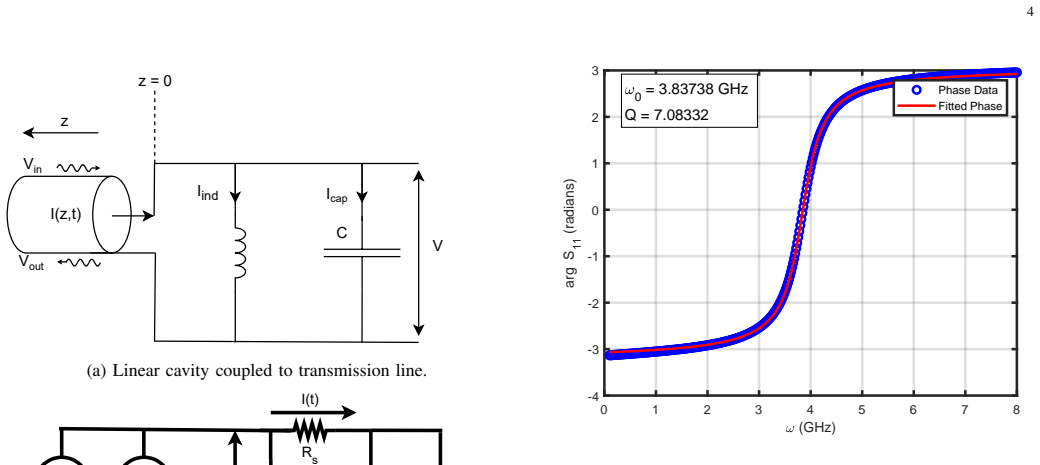
Summary. The manuscript proposes a classical time-domain design/analysis route for Josephson parametric amplifiers using open-source Josephson circuit simulators (JSIM/JoSIM), and compares the resulting gain predictions with input–output theory based on a Kerr nonlinear oscillator. The authors first derive the quantum Langevin equation and the standard frequency-domain gain expressions for a degenerate JPA, including the signal and image gain. They then construct a Norton-equivalent lumped circuit model, extract the cavity resonance frequency and quality factor from a linear reflection-phase fit, and compute S11 gain from time-domain Fourier projection. The JoSIM gain-versus-detuning and gain-versus-signal-frequency curves are presented for pump powers pin = 0.50, 0.70, 0.90, 0.95, 0.99 pc and are claimed to agree with the quantum input–output theory curves. A saturation-power map at 0.99 pc is also given, and an appendix validates the JoSIM time-domain solver against Matlab ODE45 with a reported 0.36% discrepancy.
Significance. If the comparison is set up fairly, the paper makes a useful engineering contribution: it demonstrates that a purely classical, open-source circuit solver can reproduce the narrowband gain response of a degenerate JPA, including the steep rise as the pump approaches the bifurcation point. Such a workflow could accelerate JPA design and optimization. The quantum derivation in Sec. II is standard and the linear-reflection extraction in Sec. III is clearly described. However, the central comparative claim currently rests on two undocumented normalizations—the critical pump power pc and the mapping between input power and circuit amplitude—and on a visual agreement assessment. These gaps must be closed before the 'interchangeably' claim in Sec. IV is supported. The appendix's 0.36% discrepancy only validates two classical solvers against each other; it does not test the quantum-to-classical mapping.
major comments (4)
- [Section III, Figs. 7–8; Eq. (7)] The central comparison is normalized by pin/pc, but the paper never states how pc is obtained for the JoSIM circuit. Eq. (7) defines the quantum steady-state photon number and its multistability threshold; importing that pc into the classical simulation and scaling the JoSIM pump amplitude to match the quantum pin labeling would make the agreement in Figs. 7–8 partly enforced by construction. Please specify: (i) whether pc for the circuit model is computed by observing bifurcation in the time-domain simulation, from Eq. (7) using fitted ω0, K, γ1, γ2, or from another criterion; (ii) the explicit conversion from JoSIM pump current/voltage amplitude to pin in dBm; and (iii) whether that conversion is fitted or independently derived. This is load-bearing for the claim that the classical model independently predicts the pump-power dependence.
- [Section III, Fig. 5 and Fig. 10 (Appendix)] No circuit parameter values are reported: C, Cco, Ic, Z0, and the pump and signal amplitudes are never given, nor are the quantum parameters γ1, γ2, K, and ω0 used in the input–output model. Without these values, Figs. 7–9 cannot be reproduced, and the reader cannot judge whether the quantum and classical models correspond to the same physical device. Please provide a table of all parameters and state the source or fitting procedure for each value.
- [Section III, text after Fig. 8] The statement that the JoSIM curves agree 'apart from slight discrepancies' is not quantified. There are no residuals, root-mean-square errors, or peak-gain/detuning differences shown. Given that both axes are normalized by parameters fitted from the same linear response (Fig. 6) and that the pump axis is scaled by pc, a quantitative agreement metric is necessary—especially near pin = 0.99 pc, where the gain curve is steep and small normalization differences produce large apparent changes.
- [Section IV (Summary)] The summary claim that quantum input–output theory and Josephson circuit simulators 'can be used interchangeably' exceeds what is demonstrated. The comparison covers only the degenerate signal/idler gain; it does not address output noise, phase response, squeezing, or nondegenerate operation. Please scope the claim to the quantities actually compared, or add the missing validations.
minor comments (6)
- [Fig. 4 caption] The caption lists 'pin = 0.90 pc' twice; the intended value is likely 0.95 pc, matching Fig. 3 and Fig. 7.
- [Eq. (7) and surrounding text] The critical pump power pc is mentioned repeatedly but never defined explicitly. Please add an equation or sentence defining pc, e.g., as the lowest pump power at which Eq. (7) has multiple real solutions.
- [Appendix, Eq. (28)] The notation ϕ0 is used for the single flux quantum, whereas the main text uses Φ0. In Josephson equations, the phase is usually normalized by Φ0/2π, so the definition 'ϕ0 represents the single flux quantum' is ambiguous and likely incorrect. Please harmonize the notation.
- [Eq. (24)] The Fourier projection uses e^{iω_s t}, while Eq. (11) uses e^{iω t} in the transform and e^{-iω t} in the inverse transform. Please state the sign convention consistently so that S11 and the gain expressions are unambiguous.
- [Appendix] The '0.36% discrepancy' is reported without specifying the error metric (peak voltage, RMS over a time window, etc.). Please define the metric so the agreement between JoSIM and ODE45 is meaningful.
- [Section II] There is a typo: 'Josepshon junction' should be 'Josephson junction'.
Circularity Check
No demonstrated circularity: classical gain curves are computed independently from JoSIM; shared ω0 and γ are linear-response calibrations, and the pump-power mapping gap is underdocumentation, not a shown reduction.
full rationale
The central comparison is not circular in the sense prohibited by the task. The classical gain curves (Figs. 7–8) are obtained from JoSIM time-domain simulation of the lumped circuit in Fig. 5, using S11 = Vout/Vin (Eq. 25), not from the quantum gain formula (Eq. 18). The quantum curves are computed independently from Eq. (18) after solving Eq. (7). The shared quantities are the resonance frequency and linewidth, which are extracted from the linear reflection phase of the same circuit (Fig. 6, Eq. (27)) and then used to normalize the detuning axes in both frameworks. This is legitimate parameter calibration rather than fitting the target gain curves: no nonlinear gain datum enters the fit. The paper does not document the mapping between the quantum pump power pin and the JoSIM pump amplitude, nor how pcrit is obtained in the time-domain model; if pcrit were imported from Eq. (7) and the amplitude scale chosen to align the curves, the pump-power dependence would be partly enforced. However, the manuscript contains no equation or statement exhibiting that reduction, so under the hard rules this remains an underdocumentation/reproducibility concern, not a demonstrated circularity. The self-citations [16]–[19],[22] are introductory examples of circuit-simulator use and do not carry the argument. The Appendix's 0.36% JoSIM/ODE45 agreement only validates two classical solvers against each other, but that is not a circular step; it is simply not evidence for the quantum-classical correspondence. Overall: no load-bearing circular step demonstrated; score 1.
Assumptions & free parameters
free parameters (3)
- Resonance frequency ω0 and quality factor Q =
ω0 = 3.83738 GHz, Q = 7.08332
- Critical pump power pc (bifurcation power mapping) =
not stated
- Circuit element values C, Ic, Cco, Z0 and pump/signal amplitudes =
not stated
assumptions (4)
- domain assumption Rotating wave approximation and truncation of the cosine expansion to fourth order, with external flux dependence dropped (Eqs. 2-4)
- domain assumption Linearization of the quantum Langevin equation around the pumped steady state (Eq. 10)
- standard math Lumped-element and high-Q approximations for the reflection relation (Eqs. 20-27)
- domain assumption JoSIM's Josephson junction model (phase-basis Kirchhoff equations with Josephson relations) faithfully represents the lumped JPA
Cite this review
Pith. "Pith review of Time Domain Design of a Josephson Parametric Amplifier and Comparison with Input Output Theory." pith.science (2026). https://pith.science/paper/LTT7GTIF
@misc{pith2026250818396,
  author       = {Pith},
  title        = {Pith review of: Time Domain Design of a Josephson Parametric Amplifier and Comparison with Input Output Theory},
  year         = {2026},
  howpublished = {\url{https://pith.science/paper/LTT7GTIF}},
  note         = {Machine review of arXiv:2508.18396}
}
read the original abstract
Quantum-limited amplifiers, such as Josephson Traveling Wave Parametric Amplifiers (JTWPAs) and Josephson Parametric Amplifiers (JPAs), are essential components in quantum computers. They amplify low-power microwave signals from qubits at the 10 mK stage before further amplification at the 4 K stage using HEMT amplifiers. In JPAs, parametric amplification is based on the nonlinear properties of Josephson Junctions. While JPAs are typically designed and analyzed using input-output theory based on quantum physics, we propose an alternative approach based on an equivalent circuit model of JPAs, implemented using open-source Josephson circuit simulators. We compare the results with those obtained from input-output theory. This method enables the use of circuit optimizers for various objective functions and significantly reduces design time compared to quantum theory-based approaches.
Figures


Figures from the paper (8 more)



Reference graph
Works this paper leans on
-
[13]
K. He, G. Dai, Q. Yu, Y . He, C. Zhao, J. Liu, and W. Chen, “Simulation of a flux-pumped Josephson parametric amplifier with a detailed SQUID model using the harmonic balance method,” Superconductor Science and Technology, vol. 36, no. 4, 2023
work page 2023
-
[1]
Amplification and squeezing of quantum noise with a tunable Josephson metamaterial,
M. A. Castellanos-Beltran, K. D. Irwin, G. C. Hilton, L. R. Vale, and K. W. Lehnert, “Amplification and squeezing of quantum noise with a tunable Josephson metamaterial,” Nature Physics , vol. 4, no. 12, pp. 929–931, 12 2008
work page 2008
-
[2]
Un- derstanding the Saturation Power of Josephson Parametric Amplifiers Made from SQUID Arrays,
L. Planat, R. Dassonneville, J. P. Mart ´ınez, F. Foroughi, O. Buisson, W. Hasch-Guichard, C. Naud, R. Vijay, K. Murch, and N. Roch, “Un- derstanding the Saturation Power of Josephson Parametric Amplifiers Made from SQUID Arrays,” Physical Review Applied , 2019
work page 2019
-
[3]
Wideband Joseph- son parametric amplifier with integrated transmission line transformer,
L. Ranzani, G. Ribeill, B. Hassick, and K. C. Fong, “Wideband Joseph- son parametric amplifier with integrated transmission line transformer,” in 2022 IEEE International Conference on Quantum Computing and Engineering (QCE), 2022, pp. 314–319
work page 2022
-
[4]
Flux-pumped impedance-engineered broadband Josephson parametric amplifier,
J. Grebel, A. Bienfait, P. Dumur, H.-S. Chang, M.-H. Chou, C. R. Conner, G. A. Peairs, R. G. Povey, Y . P. Zhong, and A. N. Cleland, “Flux-pumped impedance-engineered broadband Josephson parametric amplifier,” Applied Physics Letters , vol. 118, no. 14, p. 142601, 04 2021
work page 2021
-
[5]
Broadband lumped-element Josephson parametric amplifier with single-step lithography,
T. Elo, T. S. Abhilash, M. R. Perelshtein, I. Lilja, E. V . Korostylev, and P. J. Hakonen, “Broadband lumped-element Josephson parametric amplifier with single-step lithography,”Applied Physics Letters, vol. 114, no. 15, p. 152601, 2019. 6
work page 2019
-
[6]
Widely Tunable, Nondegenerate Three-Wave Mixing Microwave Device Operating near the Quantum Limit,
N. Roch, E. Flurin, F. Nguyen, P. Morfin, P. Campagne-Ibarcq, M. H. Devoret, and B. Huard, “Widely Tunable, Nondegenerate Three-Wave Mixing Microwave Device Operating near the Quantum Limit,” Physical Review Letters , vol. 108, no. 14, p. 147701, 04 2012
work page 2012
-
[7]
Circuits for Josephson Parametric Amplification in Quantum Radar,
J. A. Russer, M. W ¨urth, W. Utschick, F. Bischeltsrieder, and M. Peichl, “Circuits for Josephson Parametric Amplification in Quantum Radar,” in 2023 United States National Committee of URSI National Radio Science Meeting (USNC-URSI NRSM) , 2023, pp. 315–316
work page 2023
Show all 30 references
-
[8]
Rf-driven josephson bifurcation amplifier for quantum measurement,
I. Siddiqi, R. Vijay, F. Pierre, C. M. Wilson, M. Metcalfe, C. Rigetti, L. Frunzio, and M. H. Devoret, “Rf-driven josephson bifurcation amplifier for quantum measurement,” Phys. Rev. Lett. , vol. 93, p. 207002, Nov 2004
2004
-
[9]
Effect of Higher-Order Nonlinearities on Amplification and Squeezing in Josephson Parametric Amplifiers,
S. Boutin, D. M. Toyli, A. V . Venkatramani, A. W. Eddins, I. S. Siddiqi, and A. Blais, “Effect of Higher-Order Nonlinearities on Amplification and Squeezing in Josephson Parametric Amplifiers,” Physical Review Applied, vol. 8, no. 5, p. 054030, 2017
2017
-
[10]
Input and output in damped quantum systems: Quantum stochastic differential equations and the master equation,
C. W. Gardiner and M. J. Collett, “Input and output in damped quantum systems: Quantum stochastic differential equations and the master equation,” Physical Review A , vol. 31, no. 6, pp. 3761–3774, 1985
1985
-
[11]
Controlling the dynamic range of a Josephson parametric amplifier,
C. Eichler and A. Wallraff, “Controlling the dynamic range of a Josephson parametric amplifier,”EPJ Quantum Technology, vol. 1, no. 1, p. 2, 2014
2014
-
[12]
Graph-based analysis of nonreciprocity in coupled-mode systems,
L. Ranzani and J. Aumentado, “Graph-based analysis of nonreciprocity in coupled-mode systems,” New Journal of Physics , vol. 17, no. 2, p. 023024, 2015
2015
-
[14]
A Josephson integrated circuit simu- lator (JSIM) for superconductive electronics application,
E. S. Fang and T. Van Duzer, “A Josephson integrated circuit simu- lator (JSIM) for superconductive electronics application,” in Extended Abstracts of the 1989 International Superconductive Electronics Con- ference (ISEC ’89) , 08 1989, pp. 407–410
1989
-
[15]
JoSIM – Superconductor SPICE Simulator,
J. A. Delport, K. Jackman, P. L. Roux, and C. J. Fourie, “JoSIM – Superconductor SPICE Simulator,” IEEE Transactions on Applied Superconductivity, vol. 29, no. 5, 2018, pp. 1–5
2018
-
[16]
Askerzade, A
I. Askerzade, A. Bozbey, and M. Canturk, Modern Aspects of Josephson Dynamics and Superconductivity . Springer, 2017
2017
-
[17]
JJ-Soma: Toward a Spiking Neuromorphic Processor Architecture,
M. A. Karamuftuoglu, A. Bozbey, and S. Razmkhah, “JJ-Soma: Toward a Spiking Neuromorphic Processor Architecture,” IEEE Transactions on Applied Superconductivity, vol. 33, no. 8, pp. 1–7, 2023
2023
-
[18]
Development of an Optimization Tool for RSFQ Digital Cell Library Using Particle Swarm,
Y . Tukel, A. Bozbey, and C. Tunc, “Development of an Optimization Tool for RSFQ Digital Cell Library Using Particle Swarm,” IEEE Transactions on Applied Superconductivity, vol. 23, no. 3, pp. 1700805– 1700805, 2013
2013
-
[19]
Optimization of Single Flux Quantum Circuit Based Comparators Using PSO,
Y . Tukel, A. Bozbey, and C. A. Tunc, “Optimization of Single Flux Quantum Circuit Based Comparators Using PSO,” Journal of Supercon- ductivity and Novel Magnetism , vol. 26, no. 5, pp. 1837–1841, 2013
2013
-
[20]
Experimental verification of moat design and flux trapping analysis,
C. J. Fourie and K. Jackman, “Experimental verification of moat design and flux trapping analysis,” IEEE Transactions on Applied Supercon- ductivity, vol. 31, no. 5, pp. 1–7, 2021
2021
-
[21]
How moats protect superconductor films from flux trapping,
V . K. Semenov and M. M. Khapaev, “How moats protect superconductor films from flux trapping,” IEEE Transactions on Applied Superconduc- tivity, vol. 26, no. 3, pp. 1–10, 2016
2016
-
[22]
Current resolution of a single-flux-quantum readout circuit based on current- to-time conversion toward a flux qubit system,
S. Nakamura, H. Numabe, A. Bozbey, and A. Fujimaki, “Current resolution of a single-flux-quantum readout circuit based on current- to-time conversion toward a flux qubit system,” IEEE Transactions on Applied Superconductivity, vol. 19, no. 3, pp. 973–976, 2009
2009
-
[23]
Introduction to quantum electromagnetic circuits,
U. V ool and M. Devoret, “Introduction to quantum electromagnetic circuits,” International Journal of Circuit Theory and Applications , vol. 45, no. 7, pp. 897–934, 2017
2017
-
[24]
Josephson Parametric Amplification for Circuit Quan- tum Electrodynamics: Theory and Implementation,
C. M. Quintana, “Josephson Parametric Amplification for Circuit Quan- tum Electrodynamics: Theory and Implementation,” Ph.D. dissertation, 2013
2013
-
[25]
Invited Review Article: The Josephson bifurcation amplifier,
R. Vijay, M. H. Devoret, and I. S. Siddiqi, “Invited Review Article: The Josephson bifurcation amplifier,” Review of Scientific Instruments , vol. 80, no. 11, p. 111101, 2009
2009
-
[26]
The Josephson Bifurcation Amplifier for Quantum Measurements,
I. Siddiqi, R. Vijay, F. Pierre, C. M. Wilson, L. Frunzio, M. Metcalfe, C. Rigetti, and M. H. Devoret, “The Josephson Bifurcation Amplifier for Quantum Measurements,” arXiv, 2005
2005
-
[27]
Advances in vibration analysis research,
E. Sarrouy, J. Sinou, and F. Ebrahimi, “Advances in vibration analysis research,” in Non-Linear Periodic and Quasi-Periodic Vibrations in Mechanical Systems – On the use of the Harmonic Balance Methods , 2011, pp. 419–434
2011
-
[28]
Development of a Josephson Parametric Amplifier for the Preparation and Detection of Nonclassical States of Microwave Fields,
C. Beltran, “Development of a Josephson Parametric Amplifier for the Preparation and Detection of Nonclassical States of Microwave Fields,” Ph.D. dissertation, 2010
2010
-
[29]
D. M. Pozar, Microwave Engineering, 4th Edition . Wiley, 11 2011
2011
-
[30]
Higher-order nonlinear effects in a Josephson parametric amplifier,
B. A. Kochetov and A. Fedorov, “Higher-order nonlinear effects in a Josephson parametric amplifier,” Phys. Rev. B, vol. 92, p. 224304, Dec 2015. APPENDIX In addition to the Josephson circuit based simulators for time domain analysis, we computed the signal characteristics of t...
2015
Reviewed August 5, 2026 · model on record in the stance chip above.
Discussion (0). Continue with ORCID to comment.