REVIEW 3 major objections 7 minor 1 cited by
An Effective Trajectory Planning and an Optimized Path Planning for a 6-Degree-of-Freedom Robot Manipulator
T0 review · 3 major / 7 minor · reviewed 2026-08-05 · deepseek-v4-flash
Pith's one-line read This paper shows that planning a 6-DOF robot's path can be reduced to sampling via-points, solving inverse kinematics at each, and letting Dijkstra's algorithm pick the optimal joint sequence under a chosen cost.
desk verdict A clean, honest incremental extension of CGS-based path planning to a full 6-DOF arm, but the feasible-region guarantee is not actually a guarantee—the paper admits the region overapproximates—so the central claim is weaker than it looks. read the letter →
The pith
A machine-rendered reading of the paper's core claim, the machinery that carries it, and where it could break.
The reading
What carries the argument
The key machinery is the directed graph G=(V,E) constructed from inverse-kinematics solutions: each vertex is one solution iθk at the i-th via-point, and each directed edge i,sCi+1,t carries the cost of moving from solution s at via-point i to solution t at via-point i+1. The graph is acyclic because motion proceeds forward through via-points, so Dijkstra's algorithm returns the minimal-cost sequence from any starting configuration to any ending configuration; the cost functions f1–f6 make the optimization criterion pluggable. The feasible region derived in Section 3 (for n3=±1, the exterior of a cylinder with radius d4) serves as a geometric filter for path segments, and the quintic spline
What would settle it
Select a fixed orientation with n3=0 that the authors reported as having no inverse-kinematics solution (Section 4.4). Construct a straight-line path whose every point lies in R^3, which the paper claims is the feasible region for n3=0, and re-run Algorithm 1. If the planner fails at any via-point, the claimed feasible region contains unreachable points, refuting the assumption that the region characterizes reachability.
Extended reading notes
Core claim
The central claim is that the discrete combinatorial problem of selecting one joint configuration per via-point, necessary because inverse kinematics admits multiple solutions, is exactly a shortest-path problem in a directed acyclic layered graph, and that Dijkstra's algorithm on this graph yields an optimal joint trajectory for any additive or pathwise cost. The paper demonstrates this for the myCobot 280 by computing the feasible region (explicitly for the n3=±1 case, yielding the cylinder constraint p1^2+p2^2 ≥ d4^2), generating via-points with either uniform or smooth (quintic) time parameterization, and applying six edge-cost functions: sum of joint displacements, maximum displacement,
Load-bearing premise
The computed feasible region is assumed to contain exactly the end-effector positions that are reachable with the chosen fixed orientation, so any straight segment inside it is assumed to be traversable; the paper's own experiments show this can be false (for n3=0 the region is all of R^3 yet some orientations have no IK solution).
Editorial extensions
If this is right
- A user can specify a polyline path and per-segment orientations and receive a complete joint-space trajectory without manually choosing among IK branches.
- Changing the optimization goal, such as from minimizing total joint displacement to balancing wear across joints or maximizing dexterity, requires only swapping the edge-cost function, not recomputing inverse kinematics.
- The smooth-motion parameterization gives trajectories with zero velocity and acceleration at start and end, which should reduce mechanical stress compared to constant-speed motion along the same path.
- The computing time of the optimizer is roughly proportional to the total number of IK solutions across all via-points, so the method remains practical for dense sampling (T=50) on the tested robot.
Reading between the lines
- The paper's admission that the feasible region overestimates the truly reachable set for n3=0 implies the region is best used as a quick filter for rejecting paths, not as a certificate of solvability; an inner approximation of the reachable set would make the planner's performance guarantee rigorous.
- Since the graph layers are built purely from IK solutions and edge costs, the same optimizer could be coupled with any other IK solver or with cost functions that capture dynamics, collision avoidance, or sensor constraints, extending the approach beyond the myCobot.
- The graph built is layered and only connects consecutive via-points, so the optimizer cannot explicitly bound cumulative joint drift over long paths; adding smoothness penalties across multiple segments would require a higher-order graph or a post-processing stage.
Editorial analysis
A structured set of objections, weighed in public.
Referee Report
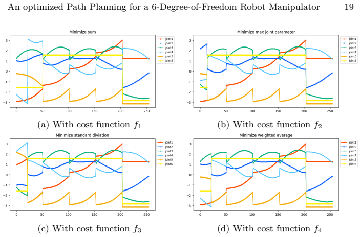
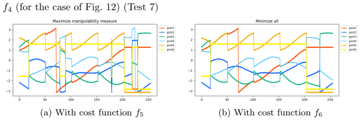
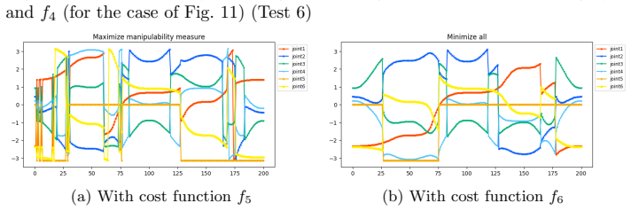
Summary. The paper proposes a three-step motion-planning pipeline for the 6-DOF myCobot 280 under a fixed end-effector orientation. First, it computes an algebraic 'feasible region' from the wrist-center polynomial system (5), treating the cases n3=±1, n3=0, and general n3 separately; for n3=±1 it derives a cylinder, for n3=0 it derives R^3, and for general n3 the quantifier elimination did not terminate (Section 3.3). Second, it generates via-points along piecewise-linear paths using either uniform or quintic-polynomial time parametrization and solves the inverse kinematics at each via-point with the companion CGS-based solver [12] (Algorithm 1). Third, it selects one IK solution per via-point by solving a shortest-path problem on a layered directed graph with Dijkstra's algorithm, using six cost functions: total joint displacement, maximum joint displacement, standard deviation of displacement, a weighted sum of these three, manipulability, and a weighted combination of the previous weighted sum with manipulability. Experiments on six rectilinear paths and one pentagon with orientation changes report computation times and joint trajectories for T=25 and T=50 segments.
Significance. The paper's main strength is the clean reduction of the IK-branch-selection problem to Dijkstra's algorithm on a layered graph, together with a transparent disclosure of the limitations of the feasible-region computation in Sections 3.3 and 4.4. If the feasible-region computation were both necessary and sufficient for the existence of an IK solution along a trajectory, the method would be a practical extension of CGS-based IK to trajectory planning with orientation constraints. However, the manuscript does not establish sufficiency, and for general orientations no feasible-region characterization is provided at all. The trajectory-planning contribution is therefore currently a heuristic whose reliability is not guaranteed, while the path-optimization contribution, though useful and clearly presented, is not compared against existing methods and is largely an application of a standard graph algorithm to the IK-solution sets. The paper is honest about these gaps, but the gaps are central to the claimed contribution.
major comments (3)
- [Section 3.2 and Section 4.4] The derivation in Section 3.2 concludes that for n3=0 the feasible region is R^3. However, Section 4.4 explicitly reports that for n3=0 some orientations produced no inverse-kinematics solution, which means the region computed from equations (5) is only a necessary condition for the full IK system (4), not a sufficient one. Consequently, the claim that a path lying inside the computed feasible region can be executed by solving IK at via-points is not supported. This is load-bearing: Algorithm 1 can fail at a via-point even when all via-points lie in the region. Please either prove sufficiency for the cases covered (e.g., n3=±1) or explicitly characterize the feasible region as a necessary-condition filter and adjust the trajectory-planning claims accordingly.
- [Section 4.3, Algorithm 1] Algorithm 1 checks the inverse kinematics only at the discrete via-points, not along the continuous line segments between them. Even if every via-point has an IK solution, there is no argument that every intermediate point on the segment is reachable. The feasible-region condition, even if sufficient at the sample points, does not imply reachability along the whole segment unless the region is convex and the IK solution set is path-connected, neither of which is established. Figures 9 and 10 plot only the via-point solutions, not a continuous execution. This is a second load-bearing gap for a trajectory planner.
- [Section 3.3] For general orientations with n3 neither 0 nor ±1, the paper states that the quantifier elimination did not terminate and thus no feasible-region characterization is provided. Since the abstract and introduction present the method for a general fixed end-effector orientation, this is a substantial incompleteness. Test 7 includes segments with n3≠0, and for those segments the method is applied without the feasible-region calculation that the paper presents as the first step. The contribution should be scoped explicitly to the cases where the feasible region is actually derived, or a feasible-region criterion for general orientations should be supplied.
minor comments (7)
- [Section 3.1, Eq. (7)] The expression 'y= ±d4d5+xp2 / p1' is ambiguous. Use parentheses, e.g., y = (±d4 d5 + x p2)/p1, to avoid confusion.
- [Section 5.2, Eq. (22)] The definition of f5 says 'p_i is the ith equation of (5)', but (5) contains three polynomial equations, not the position components p1,p2,p3. Please clarify how the Jacobian for manipulability is computed from the forward kinematics and how r=(p1,p2,p3) is obtained.
- [Section 5.2, Eq. (23)] The weights w4=1/(1+10^-6) and w5=10^-6/(1+10^-6) are introduced with only a brief order-of-magnitude remark. Please state how these values were determined and whether the optimization results are sensitive to them.
- [Section 4.4, Fig. 9] The caption says the left figure shows positions 'derived from the solutions to the inverse kinematics problem at each waypoint.' Clarify that this is a plot of discrete IK solutions, not a continuous experimental measurement of the executed trajectory.
- [Section 5.4] The comparison 'f1, f2 < f3, f4 << f5, f6' uses inconsistent formatting. Use subscripts and a clear relation, e.g., f1,f2 < f3,f4 ≪ f5,f6.
- [Figure 16 caption] The caption says 'cost functions through f1 and f4'; it should read 'cost functions f1 through f4'.
- [Reference [12]] Algorithm 1 depends on the IK solver from [12], which is listed as 'to appear'. Since the correctness of the overall method rests on that solver, consider including a brief statement of its algorithmic assumptions or a preprint URL for self-containment.
Circularity Check
No circular derivation: the planning pipeline is a genuine application of the assumed IK oracle; the admitted feasible-region overapproximation is a soundness gap, not a circular step.
full rationale
The paper's three contributions are (i) a feasible-region computation from the wrist-center equations (5), (ii) trajectory generation by sampling via-points and solving IK with the cited algorithm [12], and (iii) Dijkstra optimization over the graph of IK solutions. None of these defines its conclusion in terms of the same conclusion. The feasible region is derived from the polynomial system (5), not fitted to the inverse-kinematics results, and the paper explicitly concedes in Section 4.4 that it can overapproximate the true reachable set (n3 = 0 gives R^3 yet some orientations have no IK solution) and that the general case (Section 3.3) was not completed. That is a correctness/robustness limitation, not circularity. The IK solver [12] is an explicitly assumed input ('We also assume that we have a method to solve the inverse kinematic problem'), and the trajectory/optimization claims are conditional on it; relying on a same-author prior result for a subroutine is a dependency/validation concern, but does not reduce the claimed planning result to that citation by construction. The Dijkstra shortest-path reduction and the cost-function comparisons in Section 5 are independent algorithmic content. Thus no load-bearing circular step is exhibited.
Assumptions & free parameters
free parameters (2)
- Cost weights w1, w2, w3 =
w1=0.4, w2=0.2, w3=0.4
- Cost weights w4, w5 =
w4=1/(1+10^-6), w5=10^-6/(1+10^-6)
assumptions (2)
- domain assumption The inverse kinematics solver from the authors' companion paper [12] correctly returns all solutions for the given position and orientation.
- domain assumption The line segment path is entirely inside the feasible region required for IK to have a solution.
Cite this review
Pith. "Pith review of An Effective Trajectory Planning and an Optimized Path Planning for a 6-Degree-of-Freedom Robot Manipulator." pith.science (2026). https://pith.science/paper/6J5DMIBO
@misc{pith2026250900828,
  author       = {Pith},
  title        = {Pith review of: An Effective Trajectory Planning and an Optimized Path Planning for a 6-Degree-of-Freedom Robot Manipulator},
  year         = {2026},
  howpublished = {\url{https://pith.science/paper/6J5DMIBO}},
  note         = {Machine review of arXiv:2509.00828}
}
read the original abstract
An effective method for optimizing path planning for a specific model of a 6-degree-of-freedom (6-DOF) robot manipulator is presented as part of the motion planning of the manipulator using computer algebra. We assume that we are given a path in the form of a set of line segments that the end-effector should follow. We also assume that we have a method to solve the inverse kinematic problem of the manipulator at each via-point of the trajectory. The proposed method consists of three steps. First, we calculate the feasible region of the manipulator under a specific configuration of the end-effector. Next, we aim to find a trajectory on the line segments and a sequence of joint configurations the manipulator should follow to move the end-effector along the specified trajectory. Finally, we find the optimal combination of solutions to the inverse kinematic problem at each via-point along the trajectory by reducing the problem to a shortest-path problem of the graph and applying Dijkstra's algorithm. We show the effectiveness of the proposed method by experiments.
Figures


Figures from the paper (10 more)



Forward citations
Cited by 1 Pith paper
-
Inverse Kinematics for a 6-Degree-of-Freedom Robot Manipulator Using Comprehensive Gr\"obner Systems
A Gröbner-based method solves the inverse kinematics of the myCobot 280 by exploiting pairwise-intersecting joint axes, succeeding on 99.7% of forward-kinematics-generated test poses.
Reference graph
Works this paper leans on
-
[12]
Inverse Kinematics for a 6-Degree-of-Freedom Robot Manipulator Using Comprehensive Gr\"obner Systems
Okazaki, T., Terui, A., Mikawa, M.: Inverse Kinematics for a 6-Degree-of-Freedom Robot Manipulator Using Comprehensive Gr¨ obner Systems. In: Computer Algebra in Scientific Computing, CASC 2025. Lecture Notes in Computer Science, Springer (2025),https://doi.org/10.48550/arXiv.2509.00823, to appear
work page Pith review arXiv doi:10.48550/arxiv.2509.00823 2025
-
[1]
IEEE Transactions on Robotics33(5), 1242–1247 (2017).https://doi.org/10.1109/TRO.2017.2699670
Chen, Y., Cai, Y., Zheng, J., Thalmann, D.: Accurate and Efficient Approxima- tion of Clothoids Using B´ ezier Curves for Path Planning. IEEE Transactions on Robotics33(5), 1242–1247 (2017).https://doi.org/10.1109/TRO.2017.2699670
-
[2]
Journal of Applied Mechanics22, 215–221 (1955).https: //doi.org/10.1115/1.4011045
Denavit, J., Hartenberg, R.: A Kinematic Notation for Lower-Pair Mechanisms Based on Matrices. Journal of Applied Mechanics22, 215–221 (1955).https: //doi.org/10.1115/1.4011045
-
[3]
Dijkstra, E.W.: A note on two problems in connexion with graphs. Numer. Math. 1, 269–271 (1959).https://doi.org/10.1007/BF01386390
-
[4]
elephantrobotics.com/en/mycobot-280-m5-2023-en, accessed 2025-05-09
Elephant Robotics Co., Ltd.: myCobot 280 M5 (2023),https://www. elephantrobotics.com/en/mycobot-280-m5-2023-en, accessed 2025-05-09
work page 2023
- [5]
-
[6]
Mathematics in Computer Science6(3), 269–279 (2012).https://doi
Gasparetto, A., Boscariol, P., Lanzutti, A., Vidoni, R.: Trajectory planning in robotics. Mathematics in Computer Science6(3), 269–279 (2012).https://doi. org/10.1007/s11786-012-0123-8
-
[7]
In: Proceedings of the SCSS 2024 Work in Progress Workshop
Hatakeyama, R., Terui, A., Mikawa, M.: Towards trajectory planning of a robot manipulator with computer algebra using B´ ezier curves for obstacle avoidance. In: Proceedings of the SCSS 2024 Work in Progress Workshop. vol. 3754, pp. 21–27. Sun SITE Central Europe, R WTH Aachen University (2024),https://ceur-ws. org/Vol-3754/
work page 2024
Show all 18 references
-
[8]
Kim, C.H., H. R. Kam, S.H.L., Park, T.: R Viz: a toolkit for real domain data vi- sualization. In: Telecommunication Systems, vol. 60, pp. 337–345. Springer (2015). https://doi.org/10.1007/s11235-015-0034-5
2015 doi
-
[9]
Journal of Sensors2024(1), 5969512 (2024)
Liu, J., Yap, H.J., Khairuddin, A.S.M.: Review on Motion Planning of Robotic Ma- nipulator in Dynamic Environments. Journal of Sensors2024(1), 5969512 (2024). https://doi.org/10.1155/2024/5969512 24 Takumu Okazaki, Akira Terui, and Masahiko Mikawa
2024 doi
-
[10]
Cambridge University Press (2017)
Lynch, K.M., Park, F.C.: Modern Robotics: Mechanics, Planning, and Control. Cambridge University Press (2017)
2017
-
[11]
Science robotics7(66), eabm6074 (2022).https://doi.org/10.1126/scirobotics.abm6074
Macenski, S., Foote, T., Gerkey, B., Lalancette, C., Woodall, W.: Robot Operat- ing System 2: Design, architecture, and uses in the wild. Science robotics7(66), eabm6074 (2022).https://doi.org/10.1126/scirobotics.abm6074
2022 doi
-
[13]
In: Proceedings of the SCSS 2024 Work in Progress Work- shop
Shirato, Y., Oka, N., Terui, A., Mikawa, M.: An optimized path planning of ma- nipulator with spline curves using real quantifier elimination based on comprehen- sive gr¨ obner systems. In: Proceedings of the SCSS 2024 Work in Progress Work- shop. pp. 105–112. Sun SITE Central...
2024
-
[14]
Springer (2008).https://doi.org/10.1007/978-1-84628-642-1
Siciliano, B., Sciavicco, L., Villani, L., Oriolo, G.: Robotics: Modelling, Planning and Control. Springer (2008).https://doi.org/10.1007/978-1-84628-642-1
2008 doi
-
[15]
In: Proc
Suzuki, A., Sato, Y.: A simple algorithm to compute comprehensive Gr¨ obner bases using Gr¨ obner bases. In: Proc. ISSAC 2006. pp. 326–331 (2006).https://doi. org/10.1145/1145768.1145821
2006
-
[16]
Bordeaux: PARI/GP version2.13.1(2021), available fromhttps://pari.math.u-bordeaux.fr/
The PARI Group, Univ. Bordeaux: PARI/GP version2.13.1(2021), available fromhttps://pari.math.u-bordeaux.fr/
2021
-
[17]
The International Jour- nal of Robotics Research4(2), 3–9 (1985).https://doi.org/10.1177/ 027836498500400201
Yoshikawa, T.: Manipulability of robotic mechanisms. The International Jour- nal of Robotics Research4(2), 3–9 (1985).https://doi.org/10.1177/ 027836498500400201
1985
-
[18]
In: Computer Algebra in Scientific Computing
Yoshizawa, M., Terui, A., Mikawa, M.: Inverse Kinematics and Path Planning of Manipulator Using Real Quantifier Elimination Based on Comprehensive Gr¨ obner Systems. In: Computer Algebra in Scientific Computing. CASC 2023, Lecture Notes in Computer Science, vol. 14139, pp. 393...
2023 doi
Reviewed August 5, 2026 · model on record in the stance chip above.
Discussion (0). Continue with ORCID to comment.