REVIEW 3 major objections 6 minor 72 references
This paper claims that a small set of ruled surfaces—vertical extrusions of smooth curves that hug a shape's outer contour lines without colliding—can rough-machine material effectively with a straight hot wire.
Reviewed by Pith at T0; open to challenge. T0 means a machine referee read the full paper against a public rubric. the ladder, T0–T4 →
Vertical extrusion of collision-free splines fitted to chosen outer contours generates efficient ruled surfaces for hot-wire rough machining with fewer cuts and lower error than manual design.
T0 review reviewed 2026-08-05 challenge →
load-bearing objection A practical and novel hot-wire rough-machining pipeline with real fabrication evidence, but the collision-free guarantee is not actually conservative and the comparison numbers need cleaning up. the 3 major comments →
Outer Contour-driven Ruled Surface Generation for Linear Hot-wire Rough Machining
The pith
A machine-rendered reading of the paper's core claim, the machinery that carries it, and where it could break.
The reading
Core claim
This paper claims that an object's outer contour lines — its silhouettes from chosen viewpoints — are the right primitives for hot-wire rough-machining paths. A smooth curve hugging a silhouette without touching it, extruded along the view direction, makes a long, collision-free ruled surface that removes a large band of material in one pass. The authors build an automatic loop: genetic viewpoint search, constrained B-spline fit to the silhouette, extrusion, and material removal. On 35 shapes, including 10 physical fabrications, they report 5–15 cuts, errors mostly below 10⁻² of the box diagonal, and better accuracy than manual design or the earlier cover-to-fit method.
What carries the argument
The load-bearing object is the extruded-silhouette ruled surface: a B-spline curve fitted to the outer contour polygon g at a chosen camera, extruded along the view direction. A contour line wraps the shape and is long, so its vertical extrusion is a large, collision-free swept surface that strips material in one pass. Viewpoint selection maximizes the squared difference of rendered area images of remaining material and target. Fitting enforces the hard constraint by subdividing the control net 8 times with continuous collision detection to cap each control point's step size, while a squared-distance objective, shielding constant ϵ, mask δi, and control-point insertion reduce the error.
Load-bearing premise
The collision-free guarantee assumes that checking a control net subdivided eight times catches every collision the true B-spline curve could have with the target shape; if the curve can graze the shape while its subdivided control polygon clears it, the hard safety constraint is not actually guaranteed.
What would settle it
Take a silhouette with a deep narrow notch, fit the B-spline as the paper prescribes, then test the true curve (dense sampling or exact curve–polygon intersection) against the silhouette boundary. If any fitted curve intersects the shape while the eight-times-subdivided control net passes the continuous collision check, the 'guaranteed' collision-free claim fails; a physical version would show a wire cut that enters the target material.
If this is right
- Straight-wire rough machining becomes push-button: given a mesh and a material box, the algorithm plans a small set of collision-free cutting surfaces with no manual path input, removing the main bottleneck of earlier guaranteed-collision-free methods.
- A practical cut budget holds on complex shapes: in the paper's 22-model benchmark the pipeline stops within 15 cuts and keeps average errors mostly below one percent of the bounding-box diagonal, so fine machining starts from a close envelope.
- At equal cut counts the automatic result has lower average error than a human designer's toolpaths, and compared with the earlier cover-to-fit pipeline it uses roughly a third of the cuts with about 70% lower error on the reported cases.
- The method tolerates poor meshes: sparse, noisy, non-watertight, and non-manifold inputs all yield small errors, so raw scanned geometry is usable without cleanup.
- Results transfer to hardware: 10 models cut on a six-axis hot-wire robot match the simulated cutting surfaces, supporting feasibility beyond simulation.
Where Pith is reading between the lines
- In silhouette terms, the greedy loop approximates the shape's visual hull by a few prismatic extrusions; connecting to visual-hull theory could give a priori bounds on the number of cuts a given target requires.
- The viewpoint fitness uses projected area as a stand-in for removed volume; a volume-weighted or opacity-accumulating render should correlate better with true material removal and might reduce the number of iterations, a testable modification the paper does not explore.
- Because the paper reports that connecting cuts and returning the tool to standby dominate total fabrication time and that cut order is currently user-chosen, an obvious extension is to optimize cut sequencing over the generated surfaces; a fabrication-time benchmark would settle how much this saves.
- The outer-contour primitive is not tied to straight wires: combining straight-wire passes for convex silhouettes with curved-wire passes for concavities could extend the method to the concave and non-zero-genus shapes the paper identifies as out of reach.
Editorial analysis
A structured set of objections, weighed in public.
Referee Report
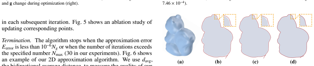
Summary. The paper proposes a pipeline for generating ruled surfaces for linear hot-wire rough machining. Given a triangular mesh M and an enclosing material box B, the method iteratively (1) selects a viewpoint with a genetic algorithm that maximizes projected-area difference between the remaining material and M, (2) extracts the outer contour of M from that viewpoint, (3) fits a collision-free B-spline curve to that contour in 2D using an adaptive squared-distance minimization with explicit collision checks, and (4) extrudes the curve along the view direction to form a ruled surface, then removes the material outside that surface. The process repeats until a volume-difference threshold or iteration cap. The experiments include ablations, stress tests, comparisons against a sampling baseline, differentiable rendering, a practitioner, and the authors' prior cover-to-fit method [6], plus 10 physical fabrications, reporting fewer cuts and lower approximation error than the baselines.
Significance. The application is timely and the empirical study is substantial: 35 models, 10 physical fabrications, stress tests on imperfect meshes, and ablations for the main algorithmic components. The central geometric observation — that silhouette-aligned extruded curves can remove material effectively in rough machining — is plausible and supported by physical examples. If the technical concerns below are addressed, this would be a solid contribution to digital fabrication and geometry processing. In particular, the comparison against practitioners and the physical fabrication validation are valuable strengths. However, the paper's hard collision-free guarantee is not established as written, and several quantitative comparison claims are inconsistent with the reported raw numbers. These points need to be fixed before the central claims can be accepted.
major comments (3)
- [Section 3.3.1, 'Optimization'] The hard cutting-validity constraint (Section 3.1) is enforced only through the step-size cap computed as follows: 'we first subdivide the control net of c k times (k = 8), then perform the continuous collision detection algorithm [68] between the subdivided control net and g to compute the maximum allowable step size tmax.' This check is not conservative for a B-spline curve. A B-spline lies in the convex hull of its control points, not on the subdivided control polygon; after k=8 knot insertions the polygon approximates the curve but does not bound it. A curve segment can intersect g while the tested polyline remains collision-free, so tmax may permit a collision. The same proxy is used in the 3D attempt (Section 4.1). To support the claim that the output surfaces 'do not collide with the input shape,' the line search must use a conservative test, e.g., checking the convex hulls of the
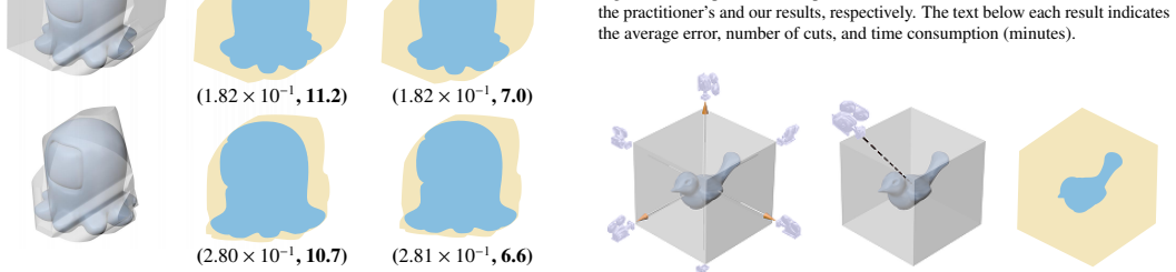
- [Section 4.1, 'Comparisons with the differentiable rendering'] The text states 'Our approximation error and viewpoint selection’s running time are both smaller.' The bird row in Fig. 13 reports differentiable rendering (1.04×10⁻³, 5, 7.5) vs. ours (7.92×10⁻³, 5, 0.6); the first quantity is the average error, so our error is about 7.6× larger. Either the tuple order or the reported value is wrong. Please correct this and re-evaluate the comparison claim.
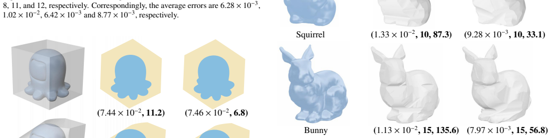
- [Section 4.1, 'Comparisons with other methods'] The summary says 'our approximation error decreases by about 70%, and we use roughly 270% fewer cuts; meanwhile, our runtime is reduced by approximately 414%.' From the Fig. 14 tuples, the error reductions are about 35%, 48%, and 39%; the cut reductions are 74%, 67%, and 76%; the runtime reductions are 71%, 80%, and 85%. None of these matches '270% fewer cuts' or '414%' (a reduction cannot exceed 100%). These quantitative claims need to be recomputed and restated, e.g., as speedup factors.
minor comments (6)
- [Abstract] The sentence 'and present an adaptive algorithm' is missing a subject; consider 'and we present an adaptive algorithm.'
- [Section 3.2.3] 'Where ϕ and θ are the elevation and azimuth' should begin with a lowercase 'where' after the equation.
- [Section 3.3.1 vs Eq. (9)] The symbol k is used both for the control-net subdivision depth (k=8) and for the angle scaling factor in Eq. (9) (k=5). Rename one to avoid confusion.
- [Section 3.3.1] The phrase 'influence interval' of a control point is used but never defined. Please define it or replace it with a precise description (e.g., the support interval of the corresponding B-spline basis function).
- [Table 1] The table formatting is broken in several rows: entries run together (e.g., '22.3Fig. 9 plane 8 6 .28×10−3 ...') and numbers are hard to parse. Please fix line breaks and spacing.
- [Section 4.1, 'Optimizing ruled surfaces'] The negative result that the 3D optimization leaves the surface unchanged is interesting, but the phrase 'has a very high probability to trigger collision' is informal. Since the 3D step is abandoned, please state the reason more precisely, e.g., 'no descent step satisfied the conservative collision test.'
Circularity Check
No significant circularity: principal outputs are externally benchmarked; collision-test issue is a soundness gap, not a circular reduction.
full rationale
Walking the claimed derivation chain: (1) The outer-contour observation is an asserted design principle, not derived from the paper's own outputs; its effectiveness is checked against manual practitioner cuts (Fig. 11) and 10 physical fabrications (Figs. 18-19), i.e., external benchmarks. (2) The viewpoint objective E^ours_material = ||I^a_Bi - I^a_M||^2 (Eq. 2) is an optimization criterion for selecting camera directions; the reported quality metric d_avg (Eq. 8) is a bidirectional geometric distance to the input, not the same fitted quantity, so no metric is renamed as a prediction. (3) The B-spline c is fit to the outer contour polygon g, and the final ruled surface is its extrusion; no equation in Section 3.3 makes the output equal to the input by construction. Enlarging the initial circle until enclosing/collision-free constraints are met is legitimate initialization, not fitting a parameter then predicting it. (4) The comparison with [6] uses the same group's prior work as a baseline, but that prior work is not cited as a premise for correctness or uniqueness; it is an empirical competitor, and the central claims also hold against practitioners. (5) The 'limitations' passages (concave/non-zero genus shapes, abandoned 3D optimization, cutting path optimality) are honesty caveats and do not reveal circularity. The one genuine weakness is a correctness/soundness concern: the collision-free guarantee relies on subdividing the control net as a proxy for the B-spline curve (Section 3.3.1), and no proof is given that this test is conservative. That is a potential violation of the hard 'cutting validity' constraint, but it is not a case where a prediction reduces to an input by definition or a self-citation chain. Per the rubric, such correctness risk is outside the circularity score.
Axiom & Free-Parameter Ledger
free parameters (7)
- termination volume threshold alpha =
0.025
- max iterations Niter =
15
- collision subdivision depth k =
8
- init d decay schedule =
1% dbb, factor 0.8/iteration
- GA sample/population sizes =
Nsample=5000, Npop=30
- 2D fitting weights =
w=1, eta0=0, eta1=1
- convex hull simplification threshold beta =
2% dbb
axioms (5)
- domain assumption Projected area difference E_ours (Eq. 2) approximates material removal volume E_material (Eq. 1) well enough for viewpoint selection.
- ad hoc to paper Collision-freedom of the k=8 subdivided control net implies collision-freedom of the B-spline curve c.
- domain assumption The outer contour line g is obtained accurately from the input mesh and viewpoint.
- domain assumption Vertical extrusion of a curve that approximates the outer contour yields a ruled surface that removes material effectively without collision.
- standard math Standard B-spline properties and Newton/CCD algorithms behave as cited.
Cite this review
Pith. "Pith review of Outer Contour-driven Ruled Surface Generation for Linear Hot-wire Rough Machining." pith.science (2026). https://pith.science/paper/XILIUJOJ
@misc{pith2026250900840,
  author       = {Pith},
  title        = {Pith review of: Outer Contour-driven Ruled Surface Generation for Linear Hot-wire Rough Machining},
  year         = {2026},
  howpublished = {\url{https://pith.science/paper/XILIUJOJ}},
  note         = {Machine review of arXiv:2509.00840}
}
read the original abstract
We propose a novel method to generate a small set of ruled surfaces that do not collide with the input shape for linear hot-wire rough machining. Central to our technique is a new observation: the ruled surfaces constructed by vertical extrusion from planar smooth curves, which approach the input shape's outer contour lines while having no collisions, are capable of removing materials effectively during rough machining. Accordingly, we develop an iterative algorithm that alternates in each iteration between computing a viewpoint to determine an outer contour line and optimizing a smooth curve to approximate that contour line under the collision-free constraint. Specifically, a view selection approach based on genetic algorithm is used to optimize the viewpoint for removing materials as much as possible, and present an adaptive algorithm to find the constrained curves. The feasibility and practicability of our method are demonstrated through 10 physical examples. Compared with manual designs, our method obtains lower errors with the same number of cuts.
Figures





Reference graph
Works this paper leans on
- [1]
-
[2]
D. Liu, M. Luo, G. Urbikain Pelayo, D. O. Trejo, D. Zhang, Position-oriented process monitoring in milling of thin-walled parts, Journal of Manufacturing Systems 60 (2021) 360–372
work page 2021
-
[3]
C. Li, G. Zhao, F. Meng, S. Yu, B. Yao, H. Liu, Multi-objective optimization of machining parameters in complete peripheral milling process with vari- able curvature workpieces, Journal of Manufacturing Processes 117 (2024) 95–110
work page 2024
-
[4]
Z. Chen, Y . Zhang, G. Zhang, W. Li, Modeling and reducing workpiece corner error due to wire deflection in wedm rough corner-cutting, Journal of Manufacturing Processes 36 (2018) 557–564
work page 2018
-
[5]
Z. Xu, H. Huang, C. Cui, X. Liao, M. Wu, Z. Xue, Complex-shaped metal parts high efficiency sawing with diamond wire, International Journal of Mechanical Sciences 250 (2023) 108306
work page 2023
- [6]
-
[7]
B. van Sosin, M. Bartoˇn, G. Elber, Accessibility for line-cutting in freeform surfaces, Comput. Aided Des. 114 (2019) 202–214
work page 2019
-
[8]
S. Duenser, R. Poranne, B. Thomaszewski, S. Coros, Robocut: Hot-wire cutting with robot-controlled flexible rods, ACM Trans. Graph. 39 (4) (2020) 98–1
work page 2020
-
[9]
R.-S. Lin, Y . Koren, Ruled surface machining on five-axis cnc machine tools, Journal of Manufacturing Processes 2 (1) (2000) 25–35. 12
work page 2000
-
[10]
B. Koc, Y .-S. Lee, Adaptive ruled layers approximation of stl models and multiaxis machining applications for rapid prototyping, Journal of Manufac- turing Systems 21 (3) (2002) 153–166
work page 2002
- [11]
-
[12]
H. Gong, L.-X. Cao, J. Liu, Improved positioning of cylindrical cutter for flank milling ruled surfaces, Comput. Aided Des. 37 (12) (2005) 1205–1213
work page 2005
-
[13]
C. Li, S. Bedi, S. Mann, Flank milling of a ruled surface with conical tools—an optimization approach, The International Journal of Advanced Manufacturing Technology 29 (2006) 1115–1124
work page 2006
-
[14]
H. Hua, T. Jia, Wire cut of double-sided minimal surfaces, The Visual Computer 34 (6) (2018) 985–995
work page 2018
- [15]
-
[16]
Y . Zhou, T. Xing, Y . Song, Y . Li, X. Zhu, G. Li, S. Ding, Digital-twin-driven geometric optimization of centrifugal impeller with free-form blades for five-axis flank milling, Journal of Manufacturing Systems 58 (2021) 22–35
work page 2021
-
[17]
B. Yamauchi, A frontier-based approach for autonomous exploration, in: Proceedings 1997 IEEE International Symposium on Computational Intelli- gence in Robotics and Automation CIRA’97.’Towards New Computational Principles for Robotics and Automation’, IEEE, 1997, pp. 146–151
work page 1997
-
[18]
J. I. Vasquez-Gomez, L. E. Sucar, R. Murrieta-Cid, J.-C. Herrera-Lozada, Tree-based search of the next best view/state for three-dimensional object reconstruction, International Journal of Advanced Robotic Systems 15 (1) (2018) 1729881418754575
work page 2018
-
[19]
J. I. Vasquez-Gomez, L. E. Sucar, R. Murrieta-Cid, View planning for 3d object reconstruction with a mobile manipulator robot, in: 2014 IEEE/RSJ International Conference on Intelligent Robots and Systems, IEEE, 2014, pp. 4227–4233
work page 2014
-
[20]
J. I. Vasquez-Gomez, L. E. Sucar, R. Murrieta-Cid, View /state planning for three-dimensional object reconstruction under uncertainty, Autonomous Robots 41 (2017) 89–109
work page 2017
-
[21]
J. I. V ´asquez-G´omez, E. L ¨opez-Damian, L. E. Sucar, View planning for 3d object reconstruction, in: 2009 IEEE/RSJ International Conference on Intelligent Robots and Systems, IEEE, 2009, pp. 4015–4020
work page 2009
-
[22]
J. I. Vasquez-Gomez, L. E. Sucar, R. Murrieta-Cid, E. Lopez-Damian, V olu- metric next-best-view planning for 3d object reconstruction with positioning error, International Journal of Advanced Robotic Systems 11 (10) (2014) 159
work page 2014
-
[23]
C. Potthast, G. S. Sukhatme, A probabilistic framework for next best view estimation in a cluttered environment, Journal of Visual Communication and Image Representation 25 (1) (2014) 148–164
work page 2014
-
[24]
J. Delmerico, S. Isler, R. Sabzevari, D. Scaramuzza, A comparison of vol- umetric information gain metrics for active 3d object reconstruction, Au- tonomous Robots 42 (2) (2018) 197–208
work page 2018
-
[25]
S. Wu, W. Sun, P. Long, H. Huang, D. Cohen-Or, M. Gong, O. Deussen, B. Chen, Quality-driven poisson-guided autoscanning, ACM Transactions on Graphics (TOG) 33 (6) (2014) 1–12
work page 2014
- [26]
-
[27]
X. Yuan, A mechanism of automatic 3d object modeling, IEEE Transactions on pattern analysis and machine intelligence 17 (3) (1995) 307–311
work page 1995
-
[28]
R. Pito, A solution to the next best view problem for automated surface acquisition, IEEE Transactions on pattern analysis and machine intelligence 21 (10) (1999) 1016–1030
work page 1999
-
[29]
S. Chen, Y . Li, Vision sensor planning for 3-d model acquisition, IEEE Transactions on Systems, Man, and Cybernetics, Part B (Cybernetics) 35 (5) (2005) 894–904
work page 2005
-
[30]
X. Zhou, B. He, Y . Li, A novel view planning method for automatic re- construction of unknown 3-d objects based on the limit visual surface, in: 2009 Fifth International Conference on Image and Graphics, IEEE, 2009, pp. 301–306
work page 2009
-
[31]
S. Kriegel, T. Bodenm¨uller, M. Suppa, G. Hirzinger, A surface-based next- best-view approach for automated 3d model completion of unknown objects, in: 2011 IEEE International Conference on Robotics and Automation, IEEE, 2011, pp. 4869–4874
work page 2011
-
[32]
M. Mendoza, J. I. Vasquez-Gomez, H. Taud, L. E. Sucar, C. Reta, Super- vised learning of the next-best-view for 3d object reconstruction, Pattern Recognition Letters 133 (2020) 224–231
work page 2020
-
[33]
Z. Wu, S. Song, A. Khosla, F. Yu, L. Zhang, X. Tang, J. Xiao, 3d shapenets: A deep representation for volumetric shapes, in: Proceedings of the IEEE conference on computer vision and pattern recognition, 2015, pp. 1912– 1920
work page 2015
-
[34]
R. Zeng, W. Zhao, Y .-J. Liu, Pc-nbv: A point cloud based deep network for e fficient next best view planning, in: 2020 IEEE /RSJ International Conference on Intelligent Robots and Systems (IROS), IEEE, 2020, pp. 7050–7057
work page 2020
-
[35]
Z. Liu, Z. Cao, J. Li, P. Guan, J. Yu, Dg-nbv: A cognitive framework for direct generation of next best view in continuous view space, IEEE Transactions on Cognitive and Developmental Systems (2024)
work page 2024
-
[36]
X. Xiao, Q. Fang, W. Peng, Y . Wang, L. Hong, J. Ye, Next best view planning via deep reinforcement leaning for 3d reconstruction of turbine blades, in: 2024 36th Chinese Control and Decision Conference (CCDC), IEEE, 2024, pp. 4022–4027
work page 2024
-
[37]
L. Li, X. Zhang, Boundary exploration of next best view policy in 3d robotic scanning, arXiv preprint arXiv:2412.10444 (2024)
Pith/arXiv arXiv 2024
-
[38]
L. Jin, X. Chen, J. R¨uckin, M. Popovi´c, Neu-nbv: Next best view planning using uncertainty estimation in image-based neural rendering, in: 2023 IEEE/RSJ International Conference on Intelligent Robots and Systems (IROS), IEEE, 2023, pp. 11305–11312
work page 2023
-
[39]
S. Lee, L. Chen, J. Wang, A. Liniger, S. Kumar, F. Yu, Uncertainty guided policy for active robotic 3d reconstruction using neural radiance fields, IEEE Robotics and Automation Letters 7 (4) (2022) 12070–12077
work page 2022
-
[40]
Y . Ran, J. Zeng, S. He, J. Chen, L. Li, Y . Chen, G. Lee, Q. Ye, Neurar: Neural uncertainty for autonomous 3d reconstruction with implicit neural representations, IEEE Robotics and Automation Letters 8 (2) (2023) 1125– 1132
work page 2023
-
[41]
X. Pan, Z. Lai, S. Song, G. Huang, Activenerf: Learning where to see with uncertainty estimation, in: European Conference on Computer Vision, Springer, 2022, pp. 230–246
work page 2022
-
[42]
D. Yan, J. Liu, F. Quan, H. Chen, M. Fu, Active implicit object reconstruction using uncertainty-guided next-best-view optimization, IEEE Robotics and Automation Letters (2023)
work page 2023
-
[43]
H. Park, Choosing nodes and knots in closed b-spline curve interpolation to point data, Computer-Aided Design 33 (13) (2001) 967–974
work page 2001
-
[44]
T. I. Vassilev, Fair interpolation and approximation of b-splines by energy minimization and points insertion, Computer-Aided Design 28 (9) (1996) 753–760
work page 1996
-
[45]
X. Wang, F. F. Cheng, B. A. Barsky, Energy and b-spline interproximation, Computer-Aided Design 29 (7) (1997) 485–496
work page 1997
-
[46]
Dierckx, Curve and surface fitting with splines, Oxford University Press, 1995
P. Dierckx, Curve and surface fitting with splines, Oxford University Press, 1995
work page 1995
- [47]
-
[48]
F. Javidrad, An accelerated simulated annealing method for b-spline curve fitting to strip-shaped scattered points, International Journal of CAD/CAM 12 (1) (2012) 9–19
work page 2012
- [49]
-
[50]
I. L. Jover, T. Debarre, S. Aziznejad, M. Unser, Coupled splines for sparse curve fitting, IEEE Transactions on Image Processing 31 (2022) 4707–4718
work page 2022
-
[51]
W. Wang, H. Pottmann, Y . Liu, Fitting b-spline curves to point clouds by curvature-based squared distance minimization, ACM Transactions on Graphics (ToG) 25 (2) (2006) 214–238
work page 2006
-
[52]
H. Pottmann, S. Leopoldseder, M. Hofer, Approximation with active b-spline curves and surfaces, in: 10th Pacific Conference on Computer Graphics and Applications, 2002. Proceedings., IEEE, 2002, pp. 8–25
work page 2002
-
[53]
Y . Liu, W. Wang, A revisit to least squares orthogonal distance fitting of parametric curves and surfaces, in: Advances in Geometric Modeling and Processing: 5th International Conference, GMP 2008, Hangzhou, China, April 23-25, 2008. Proceedings 5, Springer, 2008, pp. 384–397
work page 2008
- [54]
-
[55]
A. Ebrahimi, G. B. Loghmani, B-spline curve fitting by diagonal approxima- tion bfgs methods, Iranian Journal of Science and Technology, Transactions A: Science 43 (2019) 947–958
work page 2019
-
[56]
P. Bergstr¨om, I. S ¨oderkvist, Fitting nurbs using separable least squares techniques, International Journal of Mathematical Modelling and Numerical Optimisation 3 (4) (2012) 319–334
work page 2012
-
[57]
H. Xie, H. Qin, Automatic knot determination of nurbs for interactive geo- metric design, in: Proceedings International Conference on Shape Modeling and Applications, IEEE, 2001, pp. 267–276
work page 2001
- [58]
-
[59]
A. G´alvez, A. Iglesias, Firefly algorithm for explicit b-spline curve fitting to data points, Mathematical Problems in Engineering 2013 (1) (2013) 528215
work page 2013
-
[60]
A. Y . Hasegawa, C. Tormena, R. S. Parpinelli, B´ezier curve parametrization using a multiobjective evolutionary algorithm., International Journal of Computer Science & Applications 11 (2) (2014)
work page 2014
- [61]
-
[62]
M. Monemian, H. Rabbani, Analysis of a novel segmentation algorithm for optical coherence tomography images based on pixels intensity correlations, IEEE Transactions on Instrumentation and Measurement 70 (2020) 1–12
work page 2020
- [63]
-
[64]
C. Yang, L. Wu, Y . Chen, G. Wang, G. Weng, An active contour model based on retinex and pre-fitting reflectance for fast image segmentation, Symmetry 14 (11) (2022) 2343
work page 2022
-
[65]
M. Kass, A. Witkin, D. Terzopoulos, Snakes: Active contour models, Inter- national journal of computer vision 1 (4) (1988) 321–331
work page 1988
-
[66]
J. D. Bayer, J. Beaumont, A. Krol, Laplace–dirichlet energy field specifi- cation for deformable models. an fem approach to active contour fitting, Annals of biomedical engineering 33 (2005) 1175–1186
work page 2005
-
[67]
N. Ravi, J. Reizenstein, D. Novotny, T. Gordon, W.-Y . Lo, J. John- son, G. Gkioxari, Accelerating 3d deep learning with pytorch3d, arXiv:2007.08501 (2020)
Pith/arXiv arXiv 2007
- [68]
-
[69]
McNeel, Associates, Rhinoceros 3d (2024)
R. McNeel, Associates, Rhinoceros 3d (2024). URL https://www.rhino3d.com/
work page 2024
-
[70]
S. Liu, T. Li, W. Chen, H. Li, Soft rasterizer: A differentiable renderer for image-based 3d reasoning, in: Proceedings of the IEEE/CVF international conference on computer vision, 2019, pp. 7708–7717
work page 2019
-
[71]
D. P. Kingma, J. Ba, Adam: A method for stochastic optimization, CoRR abs/1412.6980 (2014). URL https://api.semanticscholar.org/CorpusID:6628106
Pith/arXiv arXiv 2014
-
[72]
Lynch, Modern Robotics, Cambridge University Press, 2017
K. Lynch, Modern Robotics, Cambridge University Press, 2017. 14
work page 2017
This paper was first reviewed by deepseek-v4-flash on August 5, 2026.
discussion (0)
Sign in with ORCID, Apple, or X to comment. Anyone can read and Pith papers without signing in.