REVIEW 4 major objections 5 minor 15 references
Conceptual Opto-Mechanical design of SHARP: a near-infrared multi-mode spectrograph conceived for the next-generation telescopes
T0 review · 4 major / 5 minor · reviewed 2026-08-04 · deepseek-v4-flash
Pith's one-line read SHARP's conceptual design keeps more than 90% of a diffraction-limited source's flux inside one 35-mas pixel at 2.19 µm while covering 0.95–2.45 µm at R>1000, using an all-spherical, modular cryogenic layout.
desk verdict A genuinely useful conceptual opto-mechanical design for an ELT/MORFEO near-IR spectrograph, but the performance claims lean on an idealized Gaussian PSF and should be treated as feasibility, not proof. read the letter →
The pith
A machine-rendered reading of the paper's core claim, the machinery that carries it, and where it could break.
The reading
What carries the argument
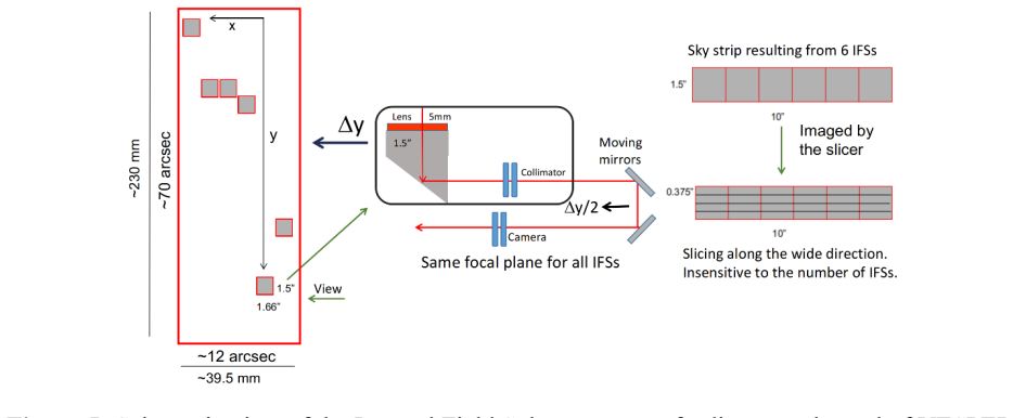
The central object is the optical train from the MORFEO second port through a Unit Selector System that switches between two front ends. NEXUS uses a configurable slit system and three dichroics to split light into four bands, each feeding a dedicated camera with a grism wheel; VESPER uses 12 movable field-selector probes, arranged in two modules, whose constant optical path is maintained by pairs of mirrors moving at half the probe displacement, feeding an image slicer with 72 micro-mirrors per stripe and four cameras per module. These mechanisms, plus an all-spherical lens prescription and modular cast-aluminum cold structure, carry the argument that the instrument can meet resolution and
What would settle it
Use the real MORFEO second-port PSF, from on-sky measurements or end-to-end AO simulations, and recompute the fraction of flux within a 35-mas pixel and the VESPER spot sizes; if the 90% encircled-energy figure drops below the requirement or the corrected field cannot cover 1 arcmin, the conceptual design's main performance claim is refuted.
Extended reading notes
Core claim
The authors claim that a single cryogenic instrument, SHARP, can exploit the AO-corrected field of MORFEO at the ELT to perform both multi-object and multi-integral-field spectroscopy in the near-infrared. The design splits NEXUS light into four simultaneous bands, each with its own camera and grism wheel, so the full 0.95–2.45 µm range is covered without reconfiguring; VESPER uses 12 movable field-selector probes and an image slicer to feed eight cameras. Encircled-energy simulations at 2.19 µm show >90% of the flux from a diffraction-limited Gaussian source falls inside one 35-mas NEXUS pixel, and VESPER spot diagrams are dominated by the input AO optics rather than SHARP itself, so both m
Load-bearing premise
The performance numbers assume the adaptive-optics system actually delivers a star image as sharp as the ELT diffraction limit across at least a 1×1 arcmin field; if the real corrected image is softer or the corrected field smaller, the claimed resolution and encircled energy would not be reached.
Editorial extensions
If this is right
- A single NEXUS exposure can cover the full 0.95–2.45 µm range without swapping gratings, avoiding the configuration changes needed by existing near-infrared multi-object spectrographs.
- Up to 30 configurable slits can be placed on a 1.2×1.2 arcmin field, giving multiplexed spectroscopy at R≈300, 2000, or 6000 depending on grism choice.
- VESPER's 12 probes return spatially resolved spectra over a 24×70 arcsec patrol area with 0.031-arcsec slices, matching the scales of giant molecular clouds at high redshift.
- The 2-m cryostat and modular cast-aluminum structure keep cryogenic power and assembly effort manageable, with front/rear cap access for maintenance.
- Because VESPER's images are limited by the input AO PSF, further improvement of SHARP's own optics will not sharpen VESPER data until the upstream adaptive-optics system improves.
Reading between the lines
- The >90%-in-one-pixel figure is an end-to-end estimate for a Gaussian input PSF; a real AO PSF with broader wings will reduce that fraction even if the FWHM matches, so the margin should be tested against realistic PSF profiles.
- The design implies a large detector count (16 2k×2k for NEXUS and 8 4k×4k for VESPER); the paper does not estimate detector cost, data volume, or readout time, which could dominate project feasibility.
- Removing the ADC for VESPER observations is proposed to gain sensitivity, but the gain is not quantified; computing it would be a natural next step.
- If the modular all-spherical design meets its goals at the ELT port, the same architecture could be offered to other ELT-class MCAO instruments with similar focal ratios, though the 1×1 arcmin corrected-field assumption would need rechecking.
Editorial analysis
A structured set of objections, weighed in public.
Referee Report
Summary. The manuscript presents the conceptual opto-mechanical design of SHARP, a near-infrared multi-mode spectrograph conceived for the ELT/MORFEO second port. SHARP consists of two subsystems: NEXUS, a multi-object spectrograph covering 0.95–2.45 µm in four simultaneous bands using 30 configurable slits and four cameras, and VESPER, a multi-integral-field unit with 12 field-selector probes, image slicers, and eight cameras. The design uses only spherical surfaces, fits in a 2 m diameter, 3 m tall cryostat, and includes mechanisms for slit configuration, field selection, and unit selection. The paper reports optical performance from ray-tracing simulations: encircled energy plots for NEXUS at 2.19 µm claim more than 90% of flux within one 35 mas pixel, and VESPER simulations are used to argue that image quality is dominated by pre-SHARP optics. The mechanical architecture is described at a conceptual level, with finite element analysis, tolerance analysis, stray-light analysis, and prototype validation deferred to future work.
Significance. If the quantitative performance claims are correct, the SHARP concept would demonstrate that a compact, all-spherical, multi-mode cryogenic spectrograph can simultaneously cover 0.95–2.45 µm at R>1000 over the MORFEO-corrected field, using a single 2 m-class cryostat. The modular opto-mechanical layout, the use of two moving mirrors for optical-path compensation in the field selectors, and the simultaneous four-band MOS design are genuinely useful concepts for next-generation instrumentation. However, the current performance evidence rests heavily on idealized PSF assumptions and lacks tolerance, thermal, and stray-light analyses. The potential significance is high, but the paper in its present form is a conceptual study with limited validation rather than a demonstrated design that meets all requirements.
major comments (4)
- [Sec. 3, Fig. 6] The encircled-energy result for NEXUS is obtained with an input 'Gaussian with FWHM equal to the ELT diffraction limit.' This is not the diffraction-limited PSF of the ELT: the actual Airy pattern, including the central obscuration and spiders, has substantial flux outside the first dark ring. At 2.19 µm, λ/D is about 12 mas, and one NEXUS pixel is 35 mas; the encircled energy of a pure Airy pattern within a radius of about 1.5λ/D is approximately 88%, before any SHARP aberrations are added, whereas a Gaussian with the same FWHM contains essentially all of its flux in the same radius. Therefore the claim that 'more than 90% of the flux falls within one NEXUS pixel' is primarily a property of the assumed input PSF, not a demonstrated performance of the NEXUS optical design. Please recompute the EE with a realistic ELT/MORFEO PSF (including obscuration, spiders, and an AO residual halo) an
- [Sec. 3, Figs. 8–10] The conclusion that VESPER's image quality is 'dominated by the optical systems that precede SHARP' is based on comparing an ideal point source (Fig. 8) with a Gaussian input whose FWHM equals the ELT diffraction limit (Fig. 9). A real MORFEO-corrected PSF is broader and contains a seeing-limited halo, so the comparison does not establish that the pre-SHARP optics dominate in real operating conditions. The authors should repeat the comparison with a more representative MORFEO PSF, or at least quantify the effect of adding a halo component with a plausible contrast ratio, before drawing this conclusion.
- [Sec. 2.1, Sec. 2.2] The throughput values stated for NEXUS ('~90% in K, neglecting the grism') and VESPER ('~75% in K, neglecting the grism') are presented without any supporting calculation, transmission budget, or reference. Given that each channel includes multiple lenses, dichroics, and folding mirrors, these values are not self-evident. Provide a throughput budget with assumed coating reflectances/transmittances, or cite the source of the numbers. This is load-bearing because the scientific motivation (e.g., sensitivity to OH-line subtraction and faint continuum) depends on preserving throughput.
- [Sec. 5] The paper explicitly defers finite element analysis, tolerance analysis, stray-light analysis, and prototype validation to future work. This is acceptable for a conceptual design, but the abstract's claim that the design is 'engineered to meet project specifications' is stronger than what is demonstrated. In particular, no tolerance sensitivity is presented, so it is unknown whether the all-spherical optical design remains diffraction-limited after manufacturing and cooldown. At minimum, a tolerance allocation or a sensitivity study for the most critical alignments (e.g., lens centering and despace, folding-mirror orientation) would be needed to support the 'meet specifications' wording.
minor comments (5)
- [Throughout] There are several typographical inconsistencies: 'James Web Space Telescope' in the introduction (and 'James Web' in Sec. 1) should be 'James Webb Space Telescope'; decimal commas appear inconsistently in Tables 2 and 3 (e.g., '3017,1', '358,3', '20,10'), which should be unified to decimal points.
- [Table 3] The entries for camera lenses C-L5 and C-L6 list '20,10 ZNSE, SILICA' and '10,20 SILICA, ZNSE' without clarifying which thickness corresponds to which material or whether these are cemented doublets or separated elements. Please define the notation.
- [References] Reference [8] is cited as a SPIE conference series but the entry contains an arXiv identifier and formatting that does not match the other references. Please convert to a consistent citation style.
- [Figs. 6–10] The captions for the spot diagrams and encircled-energy plots do not state which field positions and wavelengths are used, nor whether the plots include the pre-SHARP optics. Adding these details would make the figures interpretable without searching the text.
- [Sec. 2.2] The sentence describing the VESPER field selector movement says the FSs 'can be deployed over a range of ∼70" along the y-axis' and later says the probed area is 'approximately 24"×70"'; this geometry is not fully clear. A sketch or explicit statement of how 12 FSs (6 per module) map to the 24"×70" field would help.
Circularity Check
No significant circularity: the EE and image-quality claims are conditional on an explicitly stated input PSF and a concrete optical design, not on the paper's own conclusions.
full rationale
The derivation chain is self-contained in the sense that scientific requirements are external inputs, the optical design is a constructive engineering layout with explicit lens prescriptions, and the performance simulations propagate a stated input PSF through that design. The 'more than 90% within one pixel' statement is presented as a simulation result with the input 'a Gaussian with FWHM equal to the ELT diffraction limit' (Sec. 3, Fig. 6); this is an assumption about the delivered PSF, not a fitted parameter or a restatement of the conclusion. The VESPER comparison between a point-source simulation and a diffraction-limited Gaussian input is a controlled comparison showing that the assumed input dominates over the instrument's own blur; it does not define the conclusion into the premise. The only self-citation (Saracco et al.) is used for scientific drivers and a future slit-rotation concept, not as proof of the optical performance. The identified weakness—using an idealized Gaussian PSF instead of an Airy/MORFEO PSF—is a robustness/correctness concern about the realism of the assumed input, not circularity. Per the rules, unrealistic assumptions are not circular, so the score remains minimal.
Assumptions & free parameters
free parameters (5)
- Optical prescriptions for 12 cameras (lens radii, thicknesses, materials)
- Slit length 2.4 arcsec and maximum 30 slits =
2.4 arcsec, 30 slits
- Operating temperature range 70-80 K =
70-80 K
- VESPER field selector deployment range ~70 arcsec =
70 arcsec
- Gear ratio 0.5 for folding mirror compensation =
0.5
assumptions (4)
- standard math Diffraction limit for ELT at 2.1 µm is approximately 12 mas
- domain assumption MORFEO provides an AO-corrected field of approximately 1.8x1.8 arcmin with a PSF approximated by a Gaussian with FWHM equal to the diffraction limit
- standard math Sky brightness in K band is about 13 mag/arcsec^2 and the thermal background model follows Planck's law with Poisson noise statistics
- domain assumption Materials such as CaF2, silica, sapphire, and Cleartran have known cryogenic optical properties
Cite this review
Pith. "Pith review of Conceptual Opto-Mechanical design of SHARP: a near-infrared multi-mode spectrograph conceived for the next-generation telescopes." pith.science (2026). https://pith.science/paper/T2OT2SAJ
@misc{pith2026250907057,
  author       = {Pith},
  title        = {Pith review of: Conceptual Opto-Mechanical design of SHARP: a near-infrared multi-mode spectrograph conceived for the next-generation telescopes},
  year         = {2026},
  howpublished = {\url{https://pith.science/paper/T2OT2SAJ}},
  note         = {Machine review of arXiv:2509.07057}
}
read the original abstract
The next generation of Extremely Large Telescopes (ELTs), with their wide apertures and advanced Multi-Conjugate Adaptive Optics (MCAO) systems, will provide unprecedented sharp and deep observations, even surpassing the capabilities of James Webb Space Telescope (JWST). SHARP, a near-infrared (0.95-2.45 {\mu}m) spectrograph, is designed to optimally exploit the collecting area and angular resolution of these forthcoming ELTs, and specifically optimized for the MCAO unit MORFEO at the ELT. SHARP includes two main units: NEXUS, a Multi-Object Spectrograph (MOS), and VESPER, a multi-Integral Field Unit. This paper outlines the opto-mechanical design of SHARP based on the scientific requirements of the project. The optical design is engineered to meet project specifications, featuring a compact mechanical structure that minimizes the required cryogenic power while ensuring ease of access for maintenance and straightforward assembly procedures.
Figures


Figures from the paper (20 more)





Reference graph
Works this paper leans on
-
[1]
P. Ciliegi, G. Agapito, M. Aliverti, et al., “MAORY/MORFEO at ELT: general overview up to the preliminary design and a look towards the final design,” in Adaptive Optics Systems VIII, L. Schreiber, D. Schmidt, and E. Vernet, Eds., Society of Photo-Optical Instrumentation Engineers (SPIE) Conference Series 12185, 1218514 (2022)
work page 2022
-
[2]
MAORY: A Multi-conjugate Adaptive Optics RelaY for ELT,
P. Ciliegi, G. Agapito, M. Aliverti, et al., “MAORY: A Multi-conjugate Adaptive Optics RelaY for ELT,” The Messenger 182, 13–16 (2021)
work page 2021
-
[3]
MICADO: The Multi-Adaptive Optics Camera for Deep Observations,
R. Davies, V. H¨ormann, S. Rabien, et al., “MICADO: The Multi-Adaptive Optics Camera for Deep Observations,” The Messenger 182, 17–21 (2021)
work page 2021
-
[4]
The MICADO first light imager for the ELT: overview, operation, simulation,
R. Davies, J. Alves, Y. Cl´enet, et al., “The MICADO first light imager for the ELT: overview, operation, simulation,” in Ground-based and Airborne Instrumentation for Astronomy VII, C. J. Evans, L. Simard, and H. Takami, Eds., Society of Photo-Optical Instrumentation Engineers (SPIE) Conference Series 10702, 107021S (2018)
work page 2018
-
[5]
http://sharp.brera.inaf.it 25
-
[6]
P. Jakobsen, P. Ferruit, C. Alves de Oliveira, et al., “The Near-Infrared Spectrograph (NIRSpec) on the JamesWebb Space Telescope. I. Overview of the instrument and its capabilities,” 661, A80 (2022)
work page 2022
-
[7]
The James Webb Space Telescope Mission,
J. P. Gardner, J. C. Mather, R. Abbott, et al., “The James Webb Space Telescope Mission,” 135, 068001 (2023)
work page 2023
-
[8]
P. Saracco, P. Conconi, C. Arcidiacono, E. Portaluri, H. Mahmoodzadeh, et al,” SHARP - A near-IR multi-mode spectrograph conceived for MORFEO@ELT” Society of Photo-Optical Instrumentation Engineers (SPIE) Conference Series 2407.06264v2. 11 Jul 2024
arXiv 2024
Show all 15 references
-
[9]
EMIR the GTC NIR multi object imager spectrograph
F. Garzón, D. Abreu, S. Barrera, S. Correa, J. J. Díaz, et al, “EMIR the GTC NIR multi object imager spectrograph” Ground-based Instrumentation for Astronomy, Proceedings of SPIE Vol. 5492,(2004)
2004
-
[10]
Status of the EMIR mechanical system
V. Sánchez, S. Barrera, S. Becerril, S. Correa, et al, “Status of the EMIR mechanical system”, Ground-based and Airborne Instrumentation for Astronomy, edited by Ian S. McLean, Masanori Proc. of SPIE Vol. 6269, 626955, (2006)
2006
-
[11]
Antonio Manescau, Ana Fragoso-López, Francisco Garzón, Jesús Patrón, ” Status of the EMIR optical system” Instrument Design and Performance for Optical/Infrared Ground-based Telescopes, Masanori Iye, Alan F. M. Moorwood, Editors, Proceedings of SPIE Vol. 4841 (2003)
2003
-
[12]
An extremely metal-poor star complex in the reionization era: Approaching Population III stars with JWST,
E. Vanzella, F. Loiacono, P. Bergamini, et al., “An extremely metal-poor star complex in the reionization era: Approaching Population III stars with JWST,” A& A 678, A173 (2023)
2023
-
[13]
Mechanical slit mask mechanism for the James Webb Space Telescope spectrometer,
S. Henein, P. Spanoudakis, P. Schwab, et al., “Mechanical slit mask mechanism for the James Webb Space Telescope spectrometer,” in Optical, Infrared, and Millimeter Space Telescopes, J. C. Mather, Ed., Society of Photo-Optical Instrumentation Engineers (SPIE) Conference Series...
2004
-
[14]
Design and development of MOSFIRE, the Multi-Object Spectrometer For Infra-Red Exploration at the Keck Observatory
Ian S. McLean, Charles C. Steidel, Harland Epps, Keith Matthew, et al, “Design and development of MOSFIRE, the Multi-Object Spectrometer For Infra-Red Exploration at the Keck Observatory” SPIE Vol 7735, 77351E-77351E-12 (2010)
2010
-
[15]
Configurable slit-mask unit of the Multi- Object Spectrometer for Infra-Red Exploration for the Keck telescope: Integration and Tests
Peter Spanoudakis, Laurent Giriens, Simon Henein, et al., “Configurable slit-mask unit of the Multi- Object Spectrometer for Infra-Red Exploration for the Keck telescope: Integration and Tests” Advanced Optical and Mechanical Technologies in Telescopes and Instrumentation, edi...
2008
Reviewed August 4, 2026 · model on record in the stance chip above.
Discussion (0). Sign in to comment.