REVIEW 5 major objections 6 minor 70 references
VIRTUS-FPP: Virtual Sensor Modeling for Fringe Projection Profilometry in NVIDIA Isaac Sim
T0 review · 5 major / 6 minor · reviewed 2026-08-15 · deepseek-v4-flash
Pith's one-line read VIRTUS-FPP claims to be the first end-to-end virtual fringe projection profilometry framework in NVIDIA Isaac Sim, achieving sub-millimeter reconstruction accuracy and a digital twin of a physical FPP system.
desk verdict Useful, honest Isaac Sim FPP testbed, but the digital-twin 'sub-millimeter' claims hang on two empirically tuned knobs (Z=1 m projector dimensions and a 1.37 scale factor) that need to be reported and ablated before the accuracy headline holds. read the letter →
The pith
A machine-rendered reading of the paper's core claim, the machinery that carries it, and where it could break.
The reading
What carries the argument
The load-bearing object is the inverse camera model of the projector, written as $$[x_w, y_w, 1]^T = Z\big((M_{\mathrm{ext}})^+ (M_{\mathrm{int}})^{-1}[u, v, 1]^T\big)$$, where $(M_{\mathrm{ext}})^+$ is the Moore–Penrose pseudo-inverse of the projector's 3x4 extrinsic matrix and $Z$ is the depth factored out by the similar-triangle constraint of pinhole projection. This identity converts a projector pixel coordinate $(u,v)$ into a metric world point along the projection ray, so the width and height of the projected fringe pattern at any working distance can be read off the corner points. It is what lets a real system's calibration matrices set the rectangular light source's physical dimensions in simulation, and the paper validates it both inside the simulator (measured vs. theoretical pattern sizes at 400–1000 mm) and against the physical scanner. The rest of the pipeline—18-step phase shifting, temporal phase unwrapping with Gray coding, and an 18-pose calibration on procedurally generated asymmetric circular boards—is the standard FPP processing chain adapted to the virtual scene.
What would settle it
Measure the projected fringe dimensions in Isaac Sim at several screen distances for a projector whose intrinsic matrix is known and entered at a reference distance other than 1 m (e.g., set width/height to the Eq. (22) values at Z = 0.4 m); if the on-screen size at 0.4 m no longer matches the physical measurements (about 202.7 mm × 323.3 mm), then the 1 m reference-distance rule is an artifact of that renderer rather than a geometric property of the inverse camera model. As a complementary check, recompute virtual reconstructions without the 1.37 factor and measure the cloud-to-mesh error against the real scan: if the error is unaffected, the factor is cosmetic; if the error degrades sharply, the claimed correspondence depends on a fitted constant rather than on the modeling alone.
Extended reading notes
Core claim
The central claim, as the authors state it, is that a rectangular light source in NVIDIA Isaac Sim can serve as a faithful digital light projector once its width and height are computed from the physical projector's calibration matrices through the inverse pinhole camera model. Concretely, they take the projector's intrinsic and extrinsic matrices, invert the intrinsic, take the Moore–Penrose pseudo-inverse of the 3x4 extrinsic, and factor out the depth $Z$ using the similar-triangle scaling that is inherent to pinhole geometry; the resulting world coordinates of the pattern corners give the metric dimensions to enter into the light source. Setting those dimensions at a reference distance of $Z = 1$ m produces projected fringe sizes that track the measured values with mean absolute errors of 1.70 mm in width and 1.42 mm in height over distances from 400 to 1000 mm. The same procedure applied to a real FPP system yields a digital twin whose reconstructions of the same object have cloud-to-mesh distance distributions peaking between 0 and 1 mm, matching the physical system; the authors note that a consistent empirically determined factor of 1.37 must be applied to virtual reconstructions to achieve this match, which they attribute to the simulation environment's optical modeling.
Load-bearing premise
The load-bearing premise is that the rectangular light source in the simulator obeys the inverse-camera-model geometry set at Z = 1 m and that the resulting reconstructions only need one fixed 1.37 scale factor to match physical measurements; if either is an implementation artifact, the claimed digital-twin fidelity is a fitted coincidence rather than a geometric prediction.
Editorial extensions
If this is right
- FPP system configurations can be prototyped and fully calibrated in simulation before any hardware is built, since the virtual calibration achieves stereo reprojection error 0.0555 and projector error 0.0486.
- Synthetic fringe datasets with exact ground truth can be produced at scale: 936 captured images for an 18-pose calibration in about five minutes, roughly 10,530 captures per hour at 3 FPS acquisition.
- A calibrated real-world FPP system can be replicated as a digital twin from its calibration matrices alone, so measurement campaigns can continue in simulation when the physical scanner is unavailable or being reconfigured.
- Domain randomization over ambient lighting and material properties becomes a routine experiment: the paper shows 12 material-lighting combinations degrading fringe visibility in the expected way, which is impractical to test systematically on real hardware.
- The 0.512 mm radial error on a 50 mm sphere places the virtual system in the same accuracy class as physical structured-light scanners, making simulation a credible testbed for precision metrology development.
Reading between the lines
- Beyond the paper's claims, the 1-meter reference-distance behavior of the rectangular light source looks like a renderer convention rather than a consequence of pinhole optics; if so, the inverse-camera-model step is portable to any simulator that normalizes projected texture size at a fixed reference plane, and the width/height computation becomes a documented platform setting rather than a physi
- A natural next test the paper motivates but does not run is to train a phase-unwrapping or reconstruction network exclusively on VIRTUS-FPP data and measure how well it transfers to real fringe images; the simulator's ground-truth annotations are exactly the resource such training needs.
- The fixed 1.37 scaling factor should be probed across multiple baselines, working distances, and object sizes: if it remains constant it is a global unit-convention correction, but if it drifts the digital twin needs a distance-dependent or geometry-dependent model rather than one post-hoc multiplier.
- Since the digital-twin validation covers a single screen distance and a single target object, the paper's own virtual-versus-theoretical dimension test across 400–1000 mm provides a ready template for a stronger multi-distance, multi-geometry validation of the twin.
Signed reviews
Editorial analysis
A structured set of objections, weighed in public.
Referee Report
Summary. The manuscript presents VIRTUS-FPP, an end-to-end virtual fringe projection profilometry framework built in NVIDIA Isaac Sim. The framework uses a pinhole camera asset and a rectangular light source with texture-based fringe projection, procedurally generates asymmetric circular calibration boards, performs virtual camera-projector calibration with 18-step phase shifting, reconstructs a sphere and a figurine, tests twelve material/lighting configurations, and constructs a digital twin of a physical FPP system by transferring calibrated camera intrinsics and computing projector dimensions from an inverse pinhole model. The central claimed results are sub-millimeter reconstruction accuracy (0.512 mm radial error on a 50 mm sphere) and digital-twin fidelity shown by cloud-to-mesh (C2M) distance histograms peaking between 0 and 1 mm for an astronaut figurine. The paper also discloses an empirically determined scaling factor of 1.37 for virtual-to-real correspondence and a Z = 1 m reference distance for the Isaac Sim projector light dimensions.
Significance. FPP simulation in Isaac Sim with end-to-end calibration and reconstruction is a timely contribution for synthetic data generation, rapid prototyping, and sim-to-real transfer in robotics and optical metrology. The standard FPP equations in Section II-A are mathematically correct, the virtual calibration reprojection errors are reasonable, and the procedural calibration board generation and high-throughput data acquisition are practical strengths. The paper is also unusually candid in its limitations discussion, explicitly disclosing rendering noise and the 1.37 scaling correction. However, the headline numerical claims rest on a single sphere fit with no uncertainty quantification and on C2M histograms that are not reported numerically, and the digital-twin comparison depends on two empirically tuned settings (the Z = 1 m reference and the 1.37 scale). If the required statistics, raw-versus-scaled analyses, and multi-distance validation are added, the results could justify the claimed sub-millimeter fidelity; as currently presented, the paper overstates the strength of its validation.
major comments (5)
- [V.D and VI.B] The digital-twin fidelity claim is not an independent validation. Section VI.B discloses that virtual FPP reconstructions "exhibit a consistent empirically calculated scaling factor of 1.37 for accurate real-world correspondence," but Section V.D does not state whether this scale was applied before computing the C2M histograms in Figure 13, and no numeric C2M mean, RMSE, or percentiles are given. A global rescale is a one-parameter fit that can bring any similarly shaped reconstruction into coarse alignment, so histograms peaking at 0-1 mm do not by themselves demonstrate simulator fidelity. Please report C2M statistics for both scaled and unscaled virtual reconstructions, and specify the exact role of the 1.37 factor in the reported comparison.
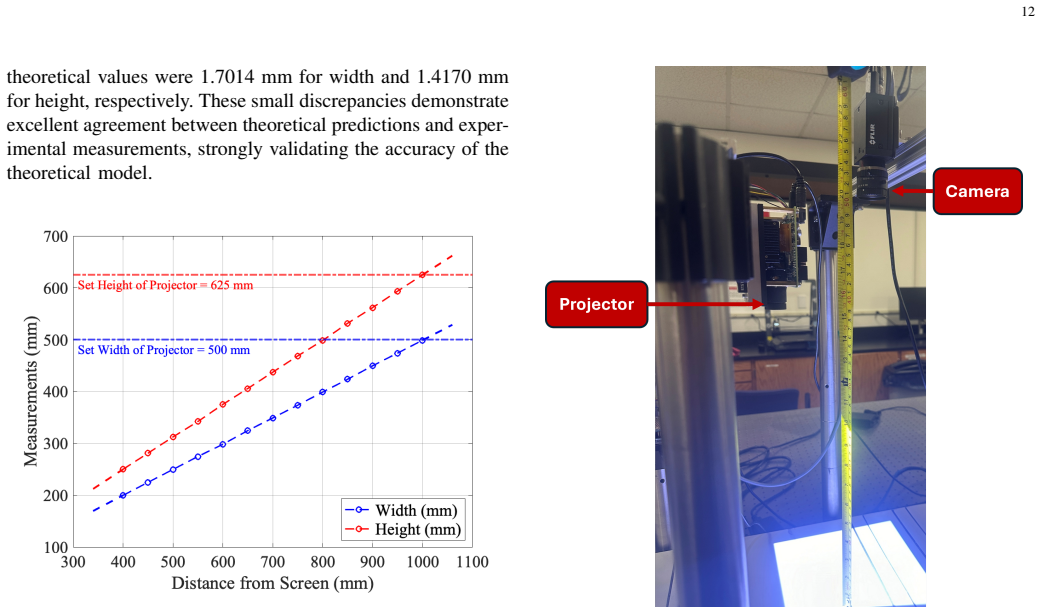
- [V.C, Eq. (22)] The projector model is validated with an implementation-specific convention rather than a derived physical property. The paper states that correct projected dimensions at 0.4 m are obtained by setting Isaac Sim's RectLight width and height to the inverse-camera-model values computed at Z = 1 m, and attributes this to a presumed internal reference distance in RectLight. This, together with the 1.37 scale correction, means the claimed sim-to-real correspondence depends on two empirically tuned parameters. Please validate the scaling relation over multiple distances, interrogate the RectLight implementation for the reference-distance behavior, or explicitly reclassify both settings as calibration parameters of the simulator; as written, the claim that projector intrinsics are established through theoretical formulation rather than empirical transfer is not fully supported.
- [V.A, Eq. (14)] The sub-millimeter accuracy claim in Eq. (14) is based on one MSAC radius fit (50.512 mm, 133,802/134,512 inliers) with no repeated trials, no standard deviation, and no variation of pose, lighting, or reconstruction parameters. Because the sphere experiment is also entirely virtual and does not involve the 1.37 scale correction, it cannot validate sim-to-real transfer. Please provide multiple trials with error bars and, if possible, a separate validation on a non-spherical target.
- [IV.A, Eqs. (12)-(13)] The calibration-board feature dimensions are reported to match intended values within 7% error (1-2 mm difference), which is large relative to the claimed sub-millimeter reconstruction accuracy. This apparent inconsistency should be resolved: either the 7% error is a misstatement or the calibration is insensitive to these dimension errors, and that insensitivity should be demonstrated. The exact source of the error (for example, texture-mapping scaling in USD) should also be quantified, since calibration-board geometry underpins all downstream accuracy claims.
- [V.B] The adverse-conditions testing section is qualitative only: no RMSE, phase error, or reconstruction error is reported for the twelve configurations in Figure 8. The conclusion that the simulator enables robust FPP development under difficult conditions is not supported by numerical evidence. Please add quantitative metrics for each material/lighting combination.
minor comments (6)
- [V.C, Eq. (25)] The dimensions 202.7 and 323.3 in Eq. (25) are labeled "expressed in meters," which is inconsistent with the physical measurements shown in Figure 12 in millimeters; if these are millimeters, correct the units.
- [Figure 13] The C2M distance histograms lack axis labels and numeric bin counts; add these so the "peaking between 0-1 mm" claim can be verified by the reader.
- [VI.B] There are typographical errors such as "syntheitc" and "dimesnions"; a careful proofreading pass is needed, although these do not affect the technical content.
- [III] The "first" claims in the abstract and Section III should be positioned against the existing Isaac Sim structured-light work in [13] and the ray-tracing FPP simulators in [48]; state explicitly which capabilities are new relative to these references.
- [Table I] Table I reports the camera focal length as 50 cm while Eqs. (15)-(17) convert between millimeters and pixels; specify the units consistently and report the focal length as either 500 mm or in pixels.
- [IV.B] The throughput claim of 3 FPS should define whether FPS refers to fringe-image capture rate or completed 3D reconstruction rate, since the text reports approximately 10,530 fringe captures per hour, or about 2.9 captures per second, not full 3D scans per second.
Circularity Check
Digital-twin fidelity is partly by construction: Fig. 13's 0-1 mm C2M histograms are produced after an empirically fitted 1.37 scaling factor and a Z=1 m projector attribute correction disclosed in Sections V.C and VI.B.
-
fitted input called prediction
[Section V.D / Section VI.B (Scaling factor consideration)]
"The virtual FPP reconstruction exhibits a consistent empirically calculated scaling factor of 1.37 for accurate real-world correspondence. This reproducible scaling behavior preserves all geometric feature relationships while providing a systematic transformation that has been experimentally determined and integrated into the processing workflow. We believe this scaling is attributed to the simulation environment's optical modeling."
The paper's central digital-twin evidence is the C2M histogram 'peaking between 0-1 mm' in Figure 13, which it describes as 'validating digital twin fidelity through sub-millimeter accuracy.' Section VI.B discloses that the virtual reconstruction is rescaled by an empirically fitted factor of 1.37 'for accurate real-world correspondence' and that this factor is 'integrated into the processing workflow.' A single global scale fitted to match real data is not an independent prediction of the inverse camera model; applying it will shift the histogram toward small C2M values even if the simulator's raw geometry has tens of percent dimensional error.
-
fitted input called prediction
[Section V.C (Digital Twin Validation, projector dimension setting)]
"However, when setting the virtual projector width and height attributes to these calculated dimensions, we observed a dimensional mismatch at the specified screen distance of 0.4 meters. Through systematic experimentation, we discovered that setting the projector's width and height attributes to the values obtained from Equation 22 with Z=1meter resulted in accurate dimensional correspondence of the projected fringe width and height with the projected fringe dimension measurements from the real-world system and the theoretical model."
The inverse camera model is presented as the theoretical basis for the digital twin, but the paper then departs from its nominal Z=0.4 m calculation and adopts Z=1 m 'through systematic experimentation' because that setting happens to match the real-world projected fringe dimensions. This is a second empirically tuned parameter in the sim-to-real chain. The agreement between the real system and the digital twin therefore depends on a simulator-specific scaling quirk that is discovered by fitting rather than derived from the cited pinhole model, so it cannot independently validate that model.
full rationale
The virtual-only accuracy claims (sphere radius 50.512 mm, R_abs=0.512 mm, Section V.A) are self-contained: the reconstruction is compared with the known sphere geometry placed in the simulator, so that part is not circular. No load-bearing self-citation or imported uniqueness theorem appears; references [46], [54], and [70] are used for comparison or methodology rather than to force the result. However, the paper's strongest sim-to-real claim, 'digital twin fidelity through sub-millimeter accuracy,' is supported by two empirically tuned corrections: the Z=1 m projector-attribute setting and the 1.37 global scaling factor. Both are disclosed as experimentally discovered and integrated into the workflow rather than predicted by the first-principles formulation. Because the C2M histograms in Figure 13 are not reported with and without the 1.37 correction, the claimed 0-1 mm peak is consistent with a one-parameter fit to the physical measurement. This makes the digital-twin validation partially circular by construction, though the virtual calibration methodology itself remains independent.
Assumptions & free parameters
free parameters (3)
- Empirical scale factor for real-world correspondence =
1.37
- Projector width and height reference distance Z_ref =
1 m
- Material parameters for baseline surface =
roughness 0.95, specular 0.15, AO-to-diffuse 0.95
assumptions (4)
- domain assumption Pinhole camera and projector models with standard intrinsic and extrinsic matrices (Equation 4) adequately represent the simulator's camera and RectLight projector.
- ad hoc to paper NVIDIA Isaac Sim's RectLight projects texture images as a coherent pinhole-like projector with a fixed 1 m reference distance for width and height attributes.
- ad hoc to paper The empirical 1.37 scaling factor corrects a global scale error without introducing distance-dependent distortion.
- domain assumption Calibration board feature dimensions computed by Equations 9 through 13 match the rendered patterns within 7% and that error is acceptable for the accuracy claims.
Cite this review
Pith. "Pith review of VIRTUS-FPP: Virtual Sensor Modeling for Fringe Projection Profilometry in NVIDIA Isaac Sim." pith.science (2026). https://pith.science/paper/UUXTQFBJ
@misc{pith2026250922685,
  author       = {Pith},
  title        = {Pith review of: VIRTUS-FPP: Virtual Sensor Modeling for Fringe Projection Profilometry in NVIDIA Isaac Sim},
  year         = {2026},
  howpublished = {\url{https://pith.science/paper/UUXTQFBJ}},
  note         = {Machine review of arXiv:2509.22685}
}
read the original abstract
Fringe projection profilometry (FPP) is a high-precision structured-light sensing technique for 3D surface reconstruction, yet its practical deployment is often constrained by complex calibration procedures, sensitivity to environmental conditions, and the high cost of physical experimentation. At the same time, robotics research increasingly relies on simulation platforms such as NVIDIA Isaac Sim for scalable development and validation, but accurate virtual representations of optical metrology sensors such as FPP are not currently available. In this work, we present VIRTUS-FPP, the first end-to-end virtual sensor modeling framework for fringe projection profilometry implemented in NVIDIA Isaac Sim, enabling physically grounded simulation of the complete FPP pipeline, including structured light projection, image formation, calibration, and 3D reconstruction, without dependence on pre-calibrated physical systems. The framework leverages an inverse camera model for projector representation, ensuring geometric and photometric fidelity consistent with structured-light principles. By bridging optical metrology and robotics simulation, VIRTUS-FPP enables high-fidelity synthetic data generation, systematic evaluation of sensing pipelines, and digital twin replication of real-world FPP systems. Experimental results demonstrate sub-millimeter reconstruction accuracy and strong correspondence between simulated and physical measurements, highlighting the framework's effectiveness and its potential to advance perception-driven robotics, simulation-to-reality transfer, and scalable optical sensor design.
Figures


Figures from the paper (9 more)




Reference graph
Works this paper leans on
-
[13]
Close the sim2real gap via physically-based structured light synthetic data simulation,
K. Bai, L. Zhang, Z. Chen, F. Wan, and J. Zhang, “Close the sim2real gap via physically-based structured light synthetic data simulation,” in2024 IEEE International Conference on Robotics and Automation (ICRA), pp. 17035–17041, IEEE, 2024
work page 2024
-
[1]
Zhang,High-Speed 3D Imaging with Digital Fringe Projection Techniques
S. Zhang,High-Speed 3D Imaging with Digital Fringe Projection Techniques. CRC Press, 1st ed., 2016
work page 2016
-
[2]
Structured-light 3d surface imaging: a tutorial,
J. Geng, “Structured-light 3d surface imaging: a tutorial,”Advances in optics and photonics, vol. 3, no. 2, pp. 128–160, 2011
work page 2011
-
[3]
Structured light techniques and applica- tions,
T. Bell, B. Li, and S. Zhang, “Structured light techniques and applica- tions,” inWiley Encyclopedia of Electrical and Electronics Engineering, pp. 1–24, John Wiley & Sons, Inc., 2016
work page 2016
-
[4]
3d imaging with fringe projection for food and agricultural applications—a tutorial,
B. Balasubramaniam, J. Li, L. Liu, and B. Li, “3d imaging with fringe projection for food and agricultural applications—a tutorial,” Electronics, vol. 12, no. 4, p. 859, 2023
work page 2023
-
[5]
Pattern codification strategies in structured light systems,
J. Salvi, J. Pages, and J. Batlle, “Pattern codification strategies in structured light systems,”Pattern recognition, vol. 37, no. 4, pp. 827– 849, 2004
work page 2004
-
[6]
Status, challenges, and future perspectives of fringe projection profilometry,
J. Xu and S. Zhang, “Status, challenges, and future perspectives of fringe projection profilometry,”Optics and Lasers in Engineering, vol. 135, p. 106193, 2020
work page 2020
-
[7]
G. Sansoni, M. Trebeschi, and F. Docchio, “Three-dimensional vision based on a combination of gray-code and phase-shift light projection: analysis and compensation of the systematic errors,”Applied optics, vol. 38, no. 31, pp. 6565–6573, 1999. 15
work page 1999
Show all 70 references
-
[8]
Machine learning enhanced high dynamic range fringe projection profilometry for in-situ layer-wise surface topography measurement during lpbf additive manufacturing,
H. Zhang, C. K. P. Vallabh, and X. Zhao, “Machine learning enhanced high dynamic range fringe projection profilometry for in-situ layer-wise surface topography measurement during lpbf additive manufacturing,” Precision Engineering, vol. 84, pp. 1–14, 2023
2023
-
[9]
High-resolution real-time 360◦ 3d surface defect inspection with fringe projection profilometry,
J. Qian, S. Feng, M. Xu, T. Tao, Y . Shang, Q. Chen, and C. Zuo, “High-resolution real-time 360◦ 3d surface defect inspection with fringe projection profilometry,”Optics and Lasers in Engineering, vol. 137, p. 106382, 2021
2021
-
[10]
Multi-view fringe projection system for surface topography measurement during metal powder bed fusion,
A. Dickins, T. Widjanarko, D. Sims-Waterhouse, A. Thompson, S. Lawes, N. Senin, and R. Leach, “Multi-view fringe projection system for surface topography measurement during metal powder bed fusion,” Journal of the Optical Society of America A, vol. 37, no. 9, pp. B93– B105, 2020
2020
-
[11]
High-resolution structured light 3d vision for fine-scale characterization to assist robotic assem- bly,
V . Suresh, W. Liu, M. Zheng, and B. Li, “High-resolution structured light 3d vision for fine-scale characterization to assist robotic assem- bly,” inDimensional Optical Metrology and Inspection for Practical Applications X, vol. 11732, p. 1173203, SPIE, April 2021
2021
-
[12]
Robotic visual servoing using fringe pro- jection profilometry,
J. Xu, G. Rao, and Z. Chen, “Robotic visual servoing using fringe pro- jection profilometry,” inOptical Metrology and Inspection for Industrial Applications V, vol. 10819, pp. 134–142, SPIE, 2018
2018
-
[14]
Corrosion characterization of engine connecting rods using fringe projection profilometry and unsupervised machine learn- ing,
A. Lakshman, F. Delzendehrooy, B. Balasubramaniam, G. E. Kremer, Y . Liao, and B. Li, “Corrosion characterization of engine connecting rods using fringe projection profilometry and unsupervised machine learn- ing,”Measurement Science and Technology, vol. 35, no. 8, p. 085021, 2024
2024
-
[15]
Quantitative evaluation of corrosion by a digital fringe projection technique,
P. S. Huang, F. Jin, and F.-P. Chiang, “Quantitative evaluation of corrosion by a digital fringe projection technique,”Optics and Lasers in Engineering, vol. 31, no. 5, pp. 371–380, 1999
1999
-
[16]
Shortwave-infrared meso- patterned imaging enables label-free mapping of tissue water and lipid content,
Y . Zhao, A. Pilvar, A. Tank, H. Peterson, J. Jiang, J. C. Aster, J. P. Dumas, M. C. Pierce, and D. Roblyer, “Shortwave-infrared meso- patterned imaging enables label-free mapping of tissue water and lipid content,”Nature communications, vol. 11, no. 1, p. 5355, 2020
2020
-
[17]
Whole 3d shape reconstruction of vascular segments under pressure via fringe projection techniques,
K. Genovese and C. Pappalettere, “Whole 3d shape reconstruction of vascular segments under pressure via fringe projection techniques,” Optics and lasers in engineering, vol. 44, no. 12, pp. 1311–1323, 2006
2006
-
[18]
Uniaxial high-speed microscale three-dimensional surface topographical measurements using fringe projection,
Y . Zheng and B. Li, “Uniaxial high-speed microscale three-dimensional surface topographical measurements using fringe projection,”Journal of Micro-and Nano-Manufacturing, vol. 8, no. 4, p. 041007, 2020
2020
-
[19]
Development and verification of a novel robot-integrated fringe projection 3d scanning system for large-scale metrology,
H. Du, X. Chen, J. Xi, C. Yu, and B. Zhao, “Development and verification of a novel robot-integrated fringe projection 3d scanning system for large-scale metrology,”Sensors, vol. 17, no. 12, p. 2886, 2017
2017
-
[20]
Scene- adaptive pattern coding-based fringe projection profilometry: diffuse surfaces identification and 3-d reconstruction in cluttered scenes,
Y . Zhao, H. Yu, Y . Zheng, Y . Zhang, D. Zheng, and J. Han, “Scene- adaptive pattern coding-based fringe projection profilometry: diffuse surfaces identification and 3-d reconstruction in cluttered scenes,”Optics Express, vol. 31, no. 20, pp. 32565–32581, 2023
2023
-
[21]
Calibration of fringe projection profilometry: A comparative review,
S. Feng, C. Zuo, L. Zhang, T. Tao, Y . Hu, W. Yin, J. Qian, and Q. Chen, “Calibration of fringe projection profilometry: A comparative review,” Optics and lasers in engineering, vol. 143, p. 106622, 2021
2021
-
[22]
Fast drawing method of circular patterns based on gaussian circles for camera calibration,
S. Asamura, Y . Naganawa, and N. Fukushima, “Fast drawing method of circular patterns based on gaussian circles for camera calibration,” in SPIE Future Sensing Technologies 2024, vol. 13083, pp. 80–86, SPIE, May 2024
2024
-
[23]
Modeling the measurement precision of fringe projection profilometry,
S. Lv and Q. Kemao, “Modeling the measurement precision of fringe projection profilometry,”Light: Science & Applications, vol. 12, no. 1, p. 257, 2023
2023
-
[24]
Absolute phase retrieval methods for digital fringe projection profilometry: A review,
S. Zhang, “Absolute phase retrieval methods for digital fringe projection profilometry: A review,”Optics and lasers in engineering, vol. 107, pp. 28–37, 2018
2018
-
[25]
Deep learning-enabled anti-ambient light approach for fringe projection profilometry,
R. Zhang, M. Duan, X. Fan, Y . Zheng, Z. Sun, J. Zheng, and Y . Jin, “Deep learning-enabled anti-ambient light approach for fringe projection profilometry,”Optics Express, vol. 30, no. 26, pp. 47672–47689, 2022
2022
-
[26]
A performance test for a fringe projection scanner in various ambient light conditions,
F. Li, D. Stoddart, and I. Zwierzak, “A performance test for a fringe projection scanner in various ambient light conditions,”Procedia CIRP, vol. 62, pp. 400–404, 2017
2017
-
[27]
Recent progresses on real-time 3d shape measurement using digital fringe projection techniques,
S. Zhang, “Recent progresses on real-time 3d shape measurement using digital fringe projection techniques,”Optics and lasers in engineering, vol. 48, no. 2, pp. 149–158, 2010
2010
-
[28]
High dynamic range 3d measurements with fringe projection profilometry: a review,
S. Feng, L. Zhang, C. Zuo, T. Tao, Q. Chen, and G. Gu, “High dynamic range 3d measurements with fringe projection profilometry: a review,” Measurement Science and Technology, vol. 29, no. 12, p. 122001, 2018
2018
-
[29]
Multi-polarization fringe projection imaging for high dynamic range objects,
B. Salahieh, Z. Chen, J. J. Rodriguez, and R. Liang, “Multi-polarization fringe projection imaging for high dynamic range objects,”Optics express, vol. 22, no. 8, pp. 10064–10071, 2014
2014
-
[30]
Experimental study for the influence of surface characteristics on the fringe patterns,
Y . Wei, J. Xi, Y . Yu, Q. Guo, and Y . Yin, “Experimental study for the influence of surface characteristics on the fringe patterns,” inOptical Metrology and Inspection for Industrial Applications III, vol. 9276, pp. 177–182, SPIE, 2014
2014
-
[31]
High-accuracy 3d shape measure- ment of translucent objects by fringe projection profilometry,
Y . Xu, H. Zhao, H. Jiang, and X. Li, “High-accuracy 3d shape measure- ment of translucent objects by fringe projection profilometry,”Optics express, vol. 27, no. 13, pp. 18421–18434, 2019
2019
-
[32]
3d shape measurement of dif- fused/specular surface by combining fringe projection and direct phase measuring deflectometry,
X. Liu, Z. Zhang, N. Gao, and Z. Meng, “3d shape measurement of dif- fused/specular surface by combining fringe projection and direct phase measuring deflectometry,”Optics Express, vol. 28, no. 19, pp. 27561– 27574, 2020
2020
-
[33]
Semi- supervised video inpainting with cycle consistency constraints,
Z. Wu, H. Xuan, C. Sun, W. Guan, K. Zhang, and Y . Yan, “Semi- supervised video inpainting with cycle consistency constraints,” in Proceedings of the IEEE/CVF Conference on Computer Vision and Pattern Recognition (CVPR), pp. 22586–22595, June 2023
2023
-
[34]
Database-assisted object retrieval for real-time 3d reconstruction,
Y . Li, A. Dai, L. Guibas, and M. Nießner, “Database-assisted object retrieval for real-time 3d reconstruction,” inComputer graphics forum, vol. 34, pp. 435–446, Wiley Online Library, 2015
2015
-
[35]
A large dataset of object scans,
S. Choi, Q.-Y . Zhou, S. Miller, and V . Koltun, “A large dataset of object scans,”arXiv preprint arXiv:1602.02481, 2016
2016 arXiv
-
[36]
Digital twins for metrology; metrology for digital twins,
L. Wright and S. Davidson, “Digital twins for metrology; metrology for digital twins,”Measurement Science and Technology, vol. 35, p. 051001, feb 2024
2024
-
[37]
Digital twin of an optical measurement system,
M. Vlaeyen, H. Haitjema, and W. Dewulf, “Digital twin of an optical measurement system,”Sensors, vol. 21, no. 19, 2021
2021
-
[38]
Lonchanet: A sliced-based cnn architecture for real-time 3d object recognition,
F. Gomez-Donoso, A. Garcia-Garcia, J. Garcia-Rodriguez, S. Orts- Escolano, and M. Cazorla, “Lonchanet: A sliced-based cnn architecture for real-time 3d object recognition,” in2017 International Joint Confer- ence on Neural Networks (IJCNN), pp. 412–418, IEEE, 2017
2017
-
[39]
Rapid tracking of extrinsic projector parameters in fringe projection using machine learning,
P. Stavroulakis, S. Chen, C. Delorme, P. Bointon, G. Tzimiropoulos, and R. Leach, “Rapid tracking of extrinsic projector parameters in fringe projection using machine learning,”Optics and Lasers in Engineering, vol. 114, pp. 7–14, 2019
2019
-
[40]
Deep learning in optical metrology: a review,
C. Zuo, J. Qian, S. Feng, W. Yin, Y . Li, P. Fan, J. Han, K. Qian, and Q. Chen, “Deep learning in optical metrology: a review,”Light: Science & Applications, vol. 11, no. 1, p. 39, 2022
2022
-
[41]
Deep learning spatial phase unwrapping: a comparative review,
K. Wang, Q. Kemao, J. Di, and J. Zhao, “Deep learning spatial phase unwrapping: a comparative review,”Advanced Photonics Nexus, vol. 1, no. 1, p. 014001, 2022
2022
-
[42]
Fringe pattern denoising based on deep learning,
K. Yan, Y . Yu, C. Huang, L. Sui, K. Qian, and A. Asundi, “Fringe pattern denoising based on deep learning,”Optics Communications, vol. 437, pp. 148–152, 2019
2019
-
[43]
S. I. Nikolenkoet al.,Synthetic data for deep learning, vol. 174. Springer, 2021
2021
-
[44]
Next-generation deep learning based on simulators and synthetic data,
C. M. De Melo, A. Torralba, L. Guibas, J. DiCarlo, R. Chellappa, and J. Hodgins, “Next-generation deep learning based on simulators and synthetic data,”Trends in cognitive sciences, vol. 26, no. 2, pp. 174– 187, 2022
2022
-
[45]
Domain randomization for transferring deep neural networks from simulation to the real world,
J. Tobin, R. Fong, A. Ray, J. Schneider, W. Zaremba, and P. Abbeel, “Domain randomization for transferring deep neural networks from simulation to the real world,” in2017 IEEE/RSJ international conference on intelligent robots and systems (IROS), pp. 23–30, IEEE, 2017
2017
-
[46]
Fringe projection profilometry by conducting deep learning from its digital twin,
Y . Zheng, S. Wang, Q. Li, and B. Li, “Fringe projection profilometry by conducting deep learning from its digital twin,”Optics Express, vol. 28, no. 24, pp. 36568–36583, 2020
2020
-
[47]
Fringe projection profilometry system verification for 3d shape measurement using virtual space of game engine,
K. Ueda, K. Ikeda, O. Koyama, and M. Yamada, “Fringe projection profilometry system verification for 3d shape measurement using virtual space of game engine,”Optical Review, vol. 28, no. 6, pp. 723–729, 2021
2021
-
[48]
Measurement simulation system of fringe projection profilometry based on ray tracing,
Q. Zhang, M. Xing, H. Li, X. Li, and T. Wang, “Measurement simulation system of fringe projection profilometry based on ray tracing,”IEEE Access, vol. 11, pp. 89616–89624, 2023
2023
-
[49]
Projection pattern pre- correction method based on projection error decoupling in fringe projection profilometry,
P. Tang, G. Sa, J. Ge, Z. Liu, and J. Tan, “Projection pattern pre- correction method based on projection error decoupling in fringe projection profilometry,”IEEE Transactions on Instrumentation and Measurement, 2025
2025
-
[50]
Cycles - blender manual,
B. Foundation, “Cycles - blender manual,” 2024
2024
-
[51]
High definition render pipeline,
U. Technologies, “High definition render pipeline,” 2024
2024
-
[52]
Optix: a general purpose ray tracing engine,
S. G. Parker, J. Bigler, A. Dietrich, H. Friedrich, J. Hoberock, D. Luebke, D. McAllister, M. McGuire, K. Morley, A. Robison,et al., “Optix: a general purpose ray tracing engine,”Acm transactions on graphics (tog), vol. 29, no. 4, pp. 1–13, 2010
2010
-
[53]
What is isaac sim?
NVIDIA, “What is isaac sim?.” https://docs.omniverse.nvidia.com/ isaacsim, 2025. Accessed: 2025-05-20. 16
2025
-
[54]
Autonomous robotic 3d scanning for smart factory planning,
A. Haroon, A. Lakshman, M. Mundy, and B. Li, “Autonomous robotic 3d scanning for smart factory planning,” inDimensional Optical Metrol- ogy and Inspection for Practical Applications XIII, vol. 13038, pp. 110– 118, SPIE, 2024
2024
-
[55]
Universal scene description (usd)
Pixar Animation Studios, “Universal scene description (usd).” https:// openusd.org/, 2025. Accessed: 2025-05-20
2025
-
[56]
Physx sdk documentation
NVIDIA, “Physx sdk documentation.” https://nvidia-omniverse.github. io/PhysX/physx/, 2025. Accessed: 2025-05-20
2025
-
[57]
Nvidia optix 9.0
NVIDIA, “Nvidia optix 9.0.” https://raytracing-docs.nvidia.com/optix9/ index.html, 2025. Accessed: 2025-05-20
2025
-
[58]
Nvidia optix ray-tracing engine as a new tool for modelling medical imaging systems,
J. Pietrzak, K. Kacperski, and M. Cie ´slar, “Nvidia optix ray-tracing engine as a new tool for modelling medical imaging systems,” inMedical Imaging 2015: Physics of Medical Imaging, vol. 9412, pp. 667–672, SPIE, 2015
2015
-
[59]
Gpu-accelerated ray tracing for optical simulation and design,
F. Mauch, M. Gronle, and W. Osten, “Gpu-accelerated ray tracing for optical simulation and design,” inClassical Optics 2014, p. IW1A.4, Optica Publishing Group, 2014
2014
-
[60]
Replicator — omniverse extensions
NVIDIA, “Replicator — omniverse extensions.” https://docs.omniverse. nvidia.com/extensions/latest/ext replicator.html, 2025. Accessed: 2025- 05-20
2025
-
[61]
Combined physics and event camera simulator for slip detection,
T. Reinold, S. Ghosh, and G. Gallego, “Combined physics and event camera simulator for slip detection,” inProceedings of the Winter Conference on Applications of Computer Vision, pp. 935–943, 2025
2025
-
[62]
Pegasus simulator: An isaac sim framework for multiple aerial vehicles simulation,
M. Jacinto, J. Pinto, J. Patrikar, J. Keller, R. Cunha, S. Scherer, and A. Pascoal, “Pegasus simulator: An isaac sim framework for multiple aerial vehicles simulation,”arXiv preprint arXiv:2307.05263, 2023
2023 arXiv
-
[63]
Oceansim: A gpu-accelerated underwater robot perception simulation framework,
J. Song, H. Ma, O. Bagoren, A. V . Sethuraman, Y . Zhang, and K. A. Skinner, “Oceansim: A gpu-accelerated underwater robot perception simulation framework,”arXiv preprint arXiv:2503.01074, 2025
2025 arXiv
-
[64]
Comparative analysis on the effect of surface reflectance for laser 3d scanner calibrator,
J. Ou, T. Xu, X. Gan, X. He, Y . Li, J. Qu, W. Zhang, and C. Cai, “Comparative analysis on the effect of surface reflectance for laser 3d scanner calibrator,”Micromachines, vol. 13, no. 10, 2022
2022
-
[65]
Optical characterization of materials for precision reference spheres for use with structured light sensors,
P. Zapico, V . Meana, E. Cuesta, and S. Mateos, “Optical characterization of materials for precision reference spheres for use with structured light sensors,”Materials, vol. 16, no. 15, 2023
2023
-
[66]
Mlesac: A new robust estimator with application to estimating image geometry,
P. H. Torr and A. Zisserman, “Mlesac: A new robust estimator with application to estimating image geometry,”Computer vision and image understanding, vol. 78, no. 1, pp. 138–156, 2000
2000
-
[67]
Camera sensors — isaac sim documentation
NVIDIA, “Camera sensors — isaac sim documentation.” https://docs.isaacsim.omniverse.nvidia.com/4.5.0/sensors/isaacsim sensors camera.html#calibrated-camera-sensors, 2025. Accessed: 2025-07-25
2025
-
[68]
Projector calibration by
I. Martynov, J.-K. Kamarainen, and L. Lensu, “Projector calibration by ”inverse camera calibration”,” inImage Analysis: 17th Scandinavian Conference, SCIA 2011, Ystad, Sweden, May 2011. Proceedings 17, pp. 536–544, Springer, 2011
2011
-
[69]
Camera models,
R. Hartley and A. Zisserman, “Camera models,” inMultiple View Geometry in Computer Vision, ch. 6, pp. 153–177, Cambridge, UK: Cambridge University Press, 2nd ed., 2003
2003
-
[70]
Characterizing the 3-dimensional printability of alginate–gelatin and nanocellulose gels via fringe projection,
A. Lakshman, Y . Huang, W. Bussey, L. Liu, and B. Li, “Characterizing the 3-dimensional printability of alginate–gelatin and nanocellulose gels via fringe projection,”Advanced Devices & Instrumentation, vol. 6, p. 0116, 2025
2025
Reviewed August 15, 2026 · model on record in the stance chip above.
Discussion (0). Continue with ORCID to comment.